P4PE-X/TE User Manual
Page 6
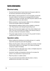
... the correct voltage in any damage, contact your dealer immediately. • To avoid short circuits, keep paper clips, screws, and staples away from connectors, slots, sockets and circuitry. • Avoid dust, humidity, and temperature extremes.
... the correct voltage in any damage, contact your dealer immediately. • To avoid short circuits, keep paper clips, screws, and staples away from connectors, slots, sockets and circuitry. • Avoid dust, humidity, and temperature extremes.

P4PE-X/TE User Manual
Page 9
P4PE-X/TE specifications summary CPU Chipset Front Side Bus (FSB) Memory Expansion slots IDE Audio LAN Special features Rear panel I/O Internal I/O Socket 478 for Intel® Pentium® 4 / Celeron processors with speeds of up to 3.06+ GHz...4X (1.5V only) 6 x PCI 2 x UltraDMA100/66/33 connectors ADI AD1888 6-channel audio CODEC Realtek® RTL8100C Fast Ethernet controller ASUS JumperFree™ mode ASUS EZ Flash ASUS CrashFree BIOS2 ASUS CPU Parameter Recall (C.P.R.) USB 2.0 ready Power Loss Restart SFS (Stepless Frequency Selection) CPU throttle Adjustable CPU Vcore 1 x Parallel port 2...
P4PE-X/TE specifications summary CPU Chipset Front Side Bus (FSB) Memory Expansion slots IDE Audio LAN Special features Rear panel I/O Internal I/O Socket 478 for Intel® Pentium® 4 / Celeron processors with speeds of up to 3.06+ GHz...4X (1.5V only) 6 x PCI 2 x UltraDMA100/66/33 connectors ADI AD1888 6-channel audio CODEC Realtek® RTL8100C Fast Ethernet controller ASUS JumperFree™ mode ASUS EZ Flash ASUS CrashFree BIOS2 ASUS CPU Parameter Recall (C.P.R.) USB 2.0 ready Power Loss Restart SFS (Stepless Frequency Selection) CPU throttle Adjustable CPU Vcore 1 x Parallel port 2...

P4PE-X/TE User Manual
Page 12
... the list below. *Overclocking mode 1.2 Package contents Check your affordable vehicle to 2GB of the above items is your P4PE-X/TE package for the following items. ASUS P4PE-X/TE motherboard ATX form factor: 12 in x 9 in 478-pin package coupled with PC3200*/2700/2100/1600 DDR SDRAM, ...; Pentium® 4 Processor via a 478-pin surface mount ZIF socket. See page 1-10 for a cost-effective desktop platform solution. The motherboard incorporates the Intel® Pentium® 4 Processor in (30.5 cm x 22.9 cm) ASUS P4PE-X/TE series support CD 1 x 80-conductor ribbon cables for UltraDMA/66/...
... the list below. *Overclocking mode 1.2 Package contents Check your affordable vehicle to 2GB of the above items is your P4PE-X/TE package for the following items. ASUS P4PE-X/TE motherboard ATX form factor: 12 in x 9 in 478-pin package coupled with PC3200*/2700/2100/1600 DDR SDRAM, ...; Pentium® 4 Processor via a 478-pin surface mount ZIF socket. See page 1-10 for a cost-effective desktop platform solution. The motherboard incorporates the Intel® Pentium® 4 Processor in (30.5 cm x 22.9 cm) ASUS P4PE-X/TE series support CD 1 x 80-conductor ribbon cables for UltraDMA/66/...
P4PE-X/TE User Manual
Page 15
... necessary arbitration and buffering for the floppy disk drive. This 2Mb firmware contains the programmable BIOS program. 10 Standby power LED. ASUS P4PE-X/TE motherboard user guide 1-5 The power supply must have at 333/266MHz operation, and 1.5V AGP interface that allows 6.4GB/s, 4.3GB..., AC'97 2.2 interface, and PCI 2.2 interface. This power connector connects the 4-pin 12V plug from the ATX 12V power supply. 2 CPU socket. Both the primary (blue) and secondary (black) connectors are slotted to six USB 2.0/1.1 ports, I /O functions including 2-channel ATA100 bus master IDE...
... necessary arbitration and buffering for the floppy disk drive. This 2Mb firmware contains the programmable BIOS program. 10 Standby power LED. ASUS P4PE-X/TE motherboard user guide 1-5 The power supply must have at 333/266MHz operation, and 1.5V AGP interface that allows 6.4GB/s, 4.3GB..., AC'97 2.2 interface, and PCI 2.2 interface. This power connector connects the 4-pin 12V plug from the ATX 12V power supply. 2 CPU socket. Both the primary (blue) and secondary (black) connectors are slotted to six USB 2.0/1.1 ports, I /O functions including 2-channel ATA100 bus master IDE...

P4PE-X/TE User Manual
Page 17
... Power Connector FLOPPY1 1.5 Motherboard layout PS/2KBMS T: Mouse B: Keyboard USB2.0 T: USB2 B: USB1 KBPWR1 USBPW12 COM1 22.86cm (9.0in) Socket 478 CPU_FAN1 CHA_FAN1 DDR DIMM1 (64/72 bit, 184-pin module) DDR DIMM2 (64/72 bit, 184-pin module) DDR DIMM3 (64... PCI1 P4PE-X/TE PCI2 AD1888 SPDIF1 CD1 AUX1 PCI3 PCI4 PCI5 PCI6 01 23 45 Intel I/O Controller Hub (ICH4) ® CR2032 3V Lithium Cell CMOS Power CLRTC ASUS ASIC with Hardware Monitor SB_PWR1 CHASSIS1 2Mbit Firmware Hub Super I/O IDE_LED1 FP_AUDIO1 USB_56 GAME1 PANEL1 30.5cm (12.0in) ASUS P4PE-X/TE motherboard ...
... Power Connector FLOPPY1 1.5 Motherboard layout PS/2KBMS T: Mouse B: Keyboard USB2.0 T: USB2 B: USB1 KBPWR1 USBPW12 COM1 22.86cm (9.0in) Socket 478 CPU_FAN1 CHA_FAN1 DDR DIMM1 (64/72 bit, 184-pin module) DDR DIMM2 (64/72 bit, 184-pin module) DDR DIMM3 (64... PCI1 P4PE-X/TE PCI2 AD1888 SPDIF1 CD1 AUX1 PCI3 PCI4 PCI5 PCI6 01 23 45 Intel I/O Controller Hub (ICH4) ® CR2032 3V Lithium Cell CMOS Power CLRTC ASUS ASIC with Hardware Monitor SB_PWR1 CHASSIS1 2Mbit Firmware Hub Super I/O IDE_LED1 FP_AUDIO1 USB_56 GAME1 PANEL1 30.5cm (12.0in) ASUS P4PE-X/TE motherboard ...
P4PE-X/TE User Manual
Page 18
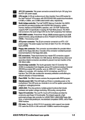
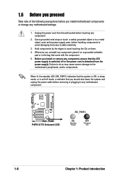
... in the bag that the ATX power supply is detached from the wall socket before handling components to avoid damaging them . 4. 1.6 Before you proceed Take note of the following precautions before removing or plugging in any motherboard component. ® P4PE-X/TE P4PE-X/TE Onboard LED SB_PWR1 ON Standby Power OFF Powered Off 1-8 Chapter 1: Product introduction...
... in the bag that the ATX power supply is detached from the wall socket before handling components to avoid damaging them . 4. 1.6 Before you proceed Take note of the following precautions before removing or plugging in any motherboard component. ® P4PE-X/TE P4PE-X/TE Onboard LED SB_PWR1 ON Standby Power OFF Powered Off 1-8 Chapter 1: Product introduction...
P4PE-X/TE User Manual
Page 20
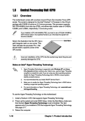
...-Threading Technology is recommended that the CPU has a gold triangular mark on one corner. Power up the system and enter BIOS Setup. The socket is set to Enabled. Gold Mark Incorrect installation of 6.4GB/s, 4.2GB/s, and 3.2GB/s, respectively. (*Overclocking mode) If you installed a ...CPU with a surface mount 478-pin Zero Insertion Force (ZIF) socket. See page 2-17. 3. Note in BIOS to ensure system stability and performance. 2. Under Linux, use the Hyper-Threading Technology on 0.13 micron ...
...-Threading Technology is recommended that the CPU has a gold triangular mark on one corner. Power up the system and enter BIOS Setup. The socket is set to Enabled. Gold Mark Incorrect installation of 6.4GB/s, 4.2GB/s, and 3.2GB/s, respectively. (*Overclocking mode) If you installed a ...CPU with a surface mount 478-pin Zero Insertion Force (ZIF) socket. See page 2-17. 3. Note in BIOS to ensure system stability and performance. 2. Under Linux, use the Hyper-Threading Technology on 0.13 micron ...

P4PE-X/TE User Manual
Page 21
... to indicate that it is locked. 6. Socket Lever Make sure that the socket lever is in one correct orientation. Install a CPU heatsink and fan following the instructions that its marked corner matches the base of the socket lever. 4. ASUS P4PE-X/TE motherboard user guide 1-11 Position the CPU above... the socket such that came with the heatsink package. 7. When the CPU is lifted up to secure the...
... to indicate that it is locked. 6. Socket Lever Make sure that the socket lever is in one correct orientation. Install a CPU heatsink and fan following the instructions that its marked corner matches the base of the socket lever. 4. ASUS P4PE-X/TE motherboard user guide 1-11 Position the CPU above... the socket such that came with the heatsink package. 7. When the CPU is lifted up to secure the...

P4PE-X/TE User Manual
Page 22
... slot 3. You may install single-sided DIMMs into DIMM2 and DIMM3 sockets at the same time but neither one can only run at 333MHz or lower frequency. ® P4PE-X/TE 80 Pins 104 Pins P4PE-X/TE 184-Pin DDR DIMM Sockets 1.9.1 Memory configurations You may not boot up to 2GB system memory... using 184-pin unbuffered non-ECC PC3200*/2700/2100/1600 DDR DIMMs. The following figure illustrates the location of the DDR DIMM sockets. (*Overclocking mode...
... slot 3. You may install single-sided DIMMs into DIMM2 and DIMM3 sockets at the same time but neither one can only run at 333MHz or lower frequency. ® P4PE-X/TE 80 Pins 104 Pins P4PE-X/TE 184-Pin DDR DIMM Sockets 1.9.1 Memory configurations You may not boot up to 2GB system memory... using 184-pin unbuffered non-ECC PC3200*/2700/2100/1600 DDR DIMMs. The following figure illustrates the location of the DDR DIMM sockets. (*Overclocking mode...

P4PE-X/TE User Manual
Page 23
... steps to ensure system stability. Unlock a DIMM socket by pressing the retaining clips outward. Align a DIMM on the socket such that the notch on the DIMM matches the break on the CPU FSB (Front Side Bus) and the type of DDR DIMM. Unlocked Retaining Clip ASUS P4PE-X/TE motherboard user guide 1-13 DIMM M2G9I08AFATT9F081AA4T 1 MT16VDDT3264AG...
... steps to ensure system stability. Unlock a DIMM socket by pressing the retaining clips outward. Align a DIMM on the socket such that the notch on the DIMM matches the break on the CPU FSB (Front Side Bus) and the type of DDR DIMM. Unlocked Retaining Clip ASUS P4PE-X/TE motherboard user guide 1-13 DIMM M2G9I08AFATT9F081AA4T 1 MT16VDDT3264AG...


