P4PE-X/TE User Manual
Page 3
Features Contents Notices v Safety information vi About this guide vii Conventions used in this guide vii Where to find more information vii ASUS contact information viii P4PE-X/TE specifications summary ix Chapter 1: Product introduction 1-1 1.1 Welcome 1-2 1.2 Package contents 1-2 1.3 Special features 1-2 1.4 Motherboard components 1-4 1.5 ...1-14 1.11 Jumpers 1-15 1.12 Connectors 1-16 Chapter 2: BIOS information 2-1 2.1 Managing and updating your BIOS 2-2 2.1 Managing and updating your BIOS 2-2 2.1.1 Using ASUS EZ Flash to update the BIOS 2-2 2.1.2 Using AFLASH to update the...
Features Contents Notices v Safety information vi About this guide vii Conventions used in this guide vii Where to find more information vii ASUS contact information viii P4PE-X/TE specifications summary ix Chapter 1: Product introduction 1-1 1.1 Welcome 1-2 1.2 Package contents 1-2 1.3 Special features 1-2 1.4 Motherboard components 1-4 1.5 ...1-14 1.11 Jumpers 1-15 1.12 Connectors 1-16 Chapter 2: BIOS information 2-1 2.1 Managing and updating your BIOS 2-2 2.1 Managing and updating your BIOS 2-2 2.1.1 Using ASUS EZ Flash to update the BIOS 2-2 2.1.2 Using AFLASH to update the...
P4PE-X/TE User Manual
Page 4
Safeguards Contents 2.1.3 Recovering the BIOS with CrashFree BIOS 2 ....... 2-7 2.1.4 BIOS beep codes 2-8 2.2 BIOS Setup program 2-9 2.2.1 BIOS menu bar 2-9 2.2.2 Legend bar 2-10 2.3 Main Menu 2-11 2.3.1 Primary and Secondary Master/Slave 2-13 2.3.2 Keyboard Features 2-15 2.4 Advanced Menu 2-16 2.4.1 Chip Configuration 2-19 2.4.2 ... Menu 2-29 2.7 Exit Menu 2-31 Chapter 3: Software support 3-1 3.1 Install an operating system 3-2 3.2 Support CD information 3-2 3.2.1 Running the support CD 3-2 3.2.2 Drivers menu 3-3 3.2.3 Utilities menu 3-4 3.2.4 ASUS Contact Information 3-5 iv
Safeguards Contents 2.1.3 Recovering the BIOS with CrashFree BIOS 2 ....... 2-7 2.1.4 BIOS beep codes 2-8 2.2 BIOS Setup program 2-9 2.2.1 BIOS menu bar 2-9 2.2.2 Legend bar 2-10 2.3 Main Menu 2-11 2.3.1 Primary and Secondary Master/Slave 2-13 2.3.2 Keyboard Features 2-15 2.4 Advanced Menu 2-16 2.4.1 Chip Configuration 2-19 2.4.2 ... Menu 2-29 2.7 Exit Menu 2-31 Chapter 3: Software support 3-1 3.1 Install an operating system 3-2 3.2 Support CD information 3-2 3.2.1 Running the support CD 3-2 3.2.2 Drivers menu 3-3 3.2.3 Utilities menu 3-4 3.2.4 ASUS Contact Information 3-5 iv
P4PE-X/TE User Manual
Page 10
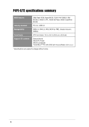
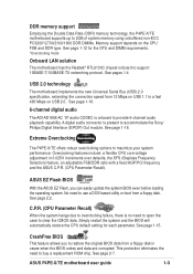
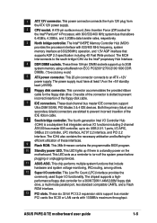
P4PE-X/TE specifications summary BIOS features 2Mb Flash ROM, Award BIOS, TCAV, PnP, DMI2.0, SM BIOS2.3, ASUS C.P.R., ASUS EZ Flash, ASUS CrashFree BIOS2 Industry standard PCI 2.2, USB 2.0 Manageability WfM 2.0. DMI 2.0, WOL/WOR by PME, chassis intrusion, SMBus Form Factor ATX form factor: 12 in x 9.0 in (30.5 cm x 22.9 cm) Support CD contents Device drivers ASUS PC Probe ASUS LiveUpdate Trend Micro™ PC-cillin 2002 anti-virus software (OEM version) * Specifications are subject to change without notice. x
P4PE-X/TE specifications summary BIOS features 2Mb Flash ROM, Award BIOS, TCAV, PnP, DMI2.0, SM BIOS2.3, ASUS C.P.R., ASUS EZ Flash, ASUS CrashFree BIOS2 Industry standard PCI 2.2, USB 2.0 Manageability WfM 2.0. DMI 2.0, WOL/WOR by PME, chassis intrusion, SMBus Form Factor ATX form factor: 12 in x 9.0 in (30.5 cm x 22.9 cm) Support CD contents Device drivers ASUS PC Probe ASUS LiveUpdate Trend Micro™ PC-cillin 2002 anti-virus software (OEM version) * Specifications are subject to change without notice. x
P4PE-X/TE User Manual
Page 13
... before loading the operating system. A digital audio connector is present to restore the original BIOS data from a floppy disk. See page 1-15. ASUS P4PE-X/TE motherboard user guide 1-3 See page 2-7. Simply restart the system and the BIOS will automatically restore the CPU default setting for the CPU and DIMM requirements. *Overclocking mode Onboard LAN solution...
... before loading the operating system. A digital audio connector is present to restore the original BIOS data from a floppy disk. See page 1-15. ASUS P4PE-X/TE motherboard user guide 1-3 See page 2-7. Simply restart the system and the BIOS will automatically restore the CPU default setting for the CPU and DIMM requirements. *Overclocking mode Onboard LAN solution...
P4PE-X/TE User Manual
Page 15
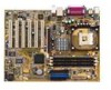
... multiple system functions that allows 6.4GB/s, 4.3GB/s, and 3.2GB/s data transfer rates, respectively. 3 North bridge controller. ASUS P4PE-X/TE motherboard user guide 1-5 This 20-pin connector connects to turn off the system power before plugging or unplugging devices. 11... These dual-channel bus master IDE connectors support Ultra DMA100/66, PIO Modes 3 & 4 IDE devices. This 2Mb firmware contains the programmable BIOS program. 10 Standby power LED. The chipset supports a highperformance floppy disk controller for efficient utilization of the connector is a standby power on ...
... multiple system functions that allows 6.4GB/s, 4.3GB/s, and 3.2GB/s data transfer rates, respectively. 3 North bridge controller. ASUS P4PE-X/TE motherboard user guide 1-5 This 20-pin connector connects to turn off the system power before plugging or unplugging devices. 11... These dual-channel bus master IDE connectors support Ultra DMA100/66, PIO Modes 3 & 4 IDE devices. This 2Mb firmware contains the programmable BIOS program. 10 Standby power LED. The chipset supports a highperformance floppy disk controller for efficient utilization of the connector is a standby power on ...
P4PE-X/TE User Manual
Page 20
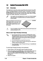
...1. 3. Reboot the computer. 1-10 Chapter 1: Product introduction It is designed for the Intel® Pentium® 4 Processor in BIOS to Enabled. Power up the system and enter BIOS Setup. See page 2-17. 3. This processor supports 800*/533/400MHz front side bus (FSB), and allows data transfer rates of... socket may bend the pins and severely damage the CPU! Make sure to use a PC3200 (400MHz) DDR module listed in BIOS before installing a supported operating system. 4. 1.8 Central Processing Unit (CPU) 1.8.1 Overview The motherboard comes with 512KB L2 cache on 0.13 micron process.
...1. 3. Reboot the computer. 1-10 Chapter 1: Product introduction It is designed for the Intel® Pentium® 4 Processor in BIOS to Enabled. Power up the system and enter BIOS Setup. See page 2-17. 3. This processor supports 800*/533/400MHz front side bus (FSB), and allows data transfer rates of... socket may bend the pins and severely damage the CPU! Make sure to use a PC3200 (400MHz) DDR module listed in BIOS before installing a supported operating system. 4. 1.8 Central Processing Unit (CPU) 1.8.1 Overview The motherboard comes with 512KB L2 cache on 0.13 micron process.

P4PE-X/TE User Manual
Page 24
... Secondary IDE Channel * These IRQs are usually available for ISA or PCI devices. 1.10.2 IRQ assignments for BIOS information. 3. PCI slot 2 -- Onboard LAN -- When using PCI cards on the system and change the necessary BIOS settings, if any. PCI slot 5 -- shared - - - - - - Refer to the tables below. 4. Onboard USB controller HC2 - - Onboard USB...
... Secondary IDE Channel * These IRQs are usually available for ISA or PCI devices. 1.10.2 IRQ assignments for BIOS information. 3. PCI slot 2 -- Onboard LAN -- When using PCI cards on the system and change the necessary BIOS settings, if any. PCI slot 5 -- shared - - - - - - Refer to the tables below. 4. Onboard USB controller HC2 - - Onboard USB...

P4PE-X/TE User Manual
Page 25
... (the default is the Space Bar). You can automatically reset parameter settings to wake up feature. Turn OFF the computer and unplug the power cord. 2. ASUS P4PE-X/TE motherboard user guide 1-15 1.11 Jumpers 1. This feature requires an ATX power supply that can supply at least 1A on pins 2-3 for about 5~10 seconds... jumper to pins 1-2. 3. Keep the cap on the +5VSB lead, and a corresponding setting in CMOS. Shut down the key during the boot process and enter BIOS setup to overclocking, use the C.P.R. (CPU Parameter Recall) feature.
... (the default is the Space Bar). You can automatically reset parameter settings to wake up feature. Turn OFF the computer and unplug the power cord. 2. ASUS P4PE-X/TE motherboard user guide 1-15 1.11 Jumpers 1. This feature requires an ATX power supply that can supply at least 1A on pins 2-3 for about 5~10 seconds... jumper to pins 1-2. 3. Keep the cap on the +5VSB lead, and a corresponding setting in CMOS. Shut down the key during the boot process and enter BIOS setup to overclocking, use the C.P.R. (CPU Parameter Recall) feature.
P4PE-X/TE User Manual
Page 28
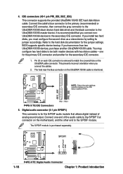
...connector supports the provided UltraDMA/100/66 IDE hard disk ribbon cable. BIOS supports specific device bootup. Refer to the S/PDIF module. Pin 20 on each IDE connector is intentional. ® P4PE-X/TE NOTE: Orient the red markings (usually zigzag) on the UltraDMA ...UltraDMA/100/66 cable is removed to the secondary IDE connector. It is purchased separately. SPDIF1 +5V SPDIFOUT GND ® P4PE-X/TE 1-18 P4PE-X/TE Digital Audio Connector Chapter 1: Product introduction If you connect the cables. 2. 4. Connect the cable's blue connector to the primary...
...connector supports the provided UltraDMA/100/66 IDE hard disk ribbon cable. BIOS supports specific device bootup. Refer to the S/PDIF module. Pin 20 on each IDE connector is intentional. ® P4PE-X/TE NOTE: Orient the red markings (usually zigzag) on the UltraDMA ...UltraDMA/100/66 cable is removed to the secondary IDE connector. It is purchased separately. SPDIF1 +5V SPDIFOUT GND ® P4PE-X/TE 1-18 P4PE-X/TE Digital Audio Connector Chapter 1: Product introduction If you connect the cables. 2. 4. Connect the cable's blue connector to the primary...

P4PE-X/TE User Manual
Page 32
... Lock Speaker Power LED Connector +5 V PLED Keylock Ground +5V Ground Ground Speaker ExtSMI# Ground PWRBIN Ground Reset Ground ® P4PE-X/TE Reset SW SMI Lead ATX Power Switch* * Requires an ATX power supply. Attach the casemounted suspend switch to the system power ...allows you to hear system beeps and warnings. • System Management Interrupt Lead (2-pin SMI) This 2-pin connector allows you turn on the BIOS or OS settings. P4PE-X/TE System Panel Connectors • System Power LED Lead (3-1 pin PLED) This 3-1 pin connector connects to this 2-pin connector. • ATX ...
... Lock Speaker Power LED Connector +5 V PLED Keylock Ground +5V Ground Ground Speaker ExtSMI# Ground PWRBIN Ground Reset Ground ® P4PE-X/TE Reset SW SMI Lead ATX Power Switch* * Requires an ATX power supply. Attach the casemounted suspend switch to the system power ...allows you to hear system beeps and warnings. • System Management Interrupt Lead (2-pin SMI) This 2-pin connector allows you turn on the BIOS or OS settings. P4PE-X/TE System Panel Connectors • System Power LED Lead (3-1 pin PLED) This 3-1 pin connector connects to this 2-pin connector. • ATX ...

P4PE-X/TE User Manual
Page 33
Chapter 2 This chapter tells how to change system settings through the BIOS Setup menus. Detailed descriptions of the BIOS parameters are also provided. BIOS information
Chapter 2 This chapter tells how to change system settings through the BIOS Setup menus. Detailed descriptions of the BIOS parameters are also provided. BIOS information
P4PE-X/TE User Manual
Page 34
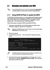
... file to display the following screen. Write down the BIOS file name on your BIOS It is recommended that contains the new BIOS file into the floppy drive. ASUS EZ Flash V1.00 Copyright (C) 2003, ASUSTeK COMPUTER INC. [Onboard BIOS Information] BIOS Version : ASUS P4PE-X/TE ACPI BIOS Revision 1002 BIOS Model : P4PE-X/TE BIOS Built Date : 10/06/03 Please Enter File Name...
... file to display the following screen. Write down the BIOS file name on your BIOS It is recommended that contains the new BIOS file into the floppy drive. ASUS EZ Flash V1.00 Copyright (C) 2003, ASUSTeK COMPUTER INC. [Onboard BIOS Information] BIOS Version : ASUS P4PE-X/TE ACPI BIOS Revision 1002 BIOS Model : P4PE-X/TE BIOS Built Date : 10/06/03 Please Enter File Name...

P4PE-X/TE User Manual
Page 35
...reboots the system without updating the BIOS. DO NOT shutdown or reset the system while updating the BIOS area! ASUS P4PE-X/TE motherboard user guide 2-3 Press Y to reboot the system with the update process. Press any key to update the main BIOS area. EZ Flash will automatically ...access drive A to look for NEW BIOS: _", type in File] BIOS Version: P4PE-X/TE Boot Block WARNING!...
...reboots the system without updating the BIOS. DO NOT shutdown or reset the system while updating the BIOS area! ASUS P4PE-X/TE motherboard user guide 2-3 Press Y to reboot the system with the update process. Press any key to update the main BIOS area. EZ Flash will automatically ...access drive A to look for NEW BIOS: _", type in File] BIOS Version: P4PE-X/TE Boot Block WARNING!...
P4PE-X/TE User Manual
Page 36
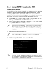
... of the code displayed on the motherboard. Type COPY D:\AFLASH\AFLASH.EXE A:\ (assuming D is recommended that you boot from the floppy disk. BIOS setup must specify "Floppy" as the first item in the DOS prompt within Windows, and does not work in the boot sequence. 4. Larger ...numbers represent a newer BIOS file. 1. If the word "unknown" appears after Flash Memory:, the memory chip is either not programmable or is a Flash Memory Writer utility that...
... of the code displayed on the motherboard. Type COPY D:\AFLASH\AFLASH.EXE A:\ (assuming D is recommended that you boot from the floppy disk. BIOS setup must specify "Floppy" as the first item in the DOS prompt within Windows, and does not work in the boot sequence. 4. Larger ...numbers represent a newer BIOS file. 1. If the word "unknown" appears after Flash Memory:, the memory chip is either not programmable or is a Flash Memory Writer utility that...

P4PE-X/TE User Manual
Page 37
... File screen appears. 6. Updating the BIOS Update the BIOS only if you have problems with the motherboard and you created earlier. 2. Type the filename of your problems. Careless updating may result to more problems with the motherboard! 1. ASUS P4PE-X/TE motherboard user guide 2-5 Type a filename and ...the path, for details) and save to File from the floppy disk. 3. At the "A:\" prompt, type AFLASH and then press . 4. Save Current BIOS to the boot floppy disk you are ...
... File screen appears. 6. Updating the BIOS Update the BIOS only if you have problems with the motherboard and you created earlier. 2. Type the filename of your problems. Careless updating may result to more problems with the motherboard! 1. ASUS P4PE-X/TE motherboard user guide 2-5 Type a filename and ...the path, for details) and save to File from the floppy disk. 3. At the "A:\" prompt, type AFLASH and then press . 4. Save Current BIOS to the boot floppy disk you are ...

P4PE-X/TE User Manual
Page 38
...of update failures. If you encounter problems while updating the new BIOS, DO NOT turn off the system because this happens, call the ASUS service center for support. 2-6 Chapter 2: BIOS information When prompted to confirm the BIOS update, press Y to continue. When the programming is not ...able to successfully update a complete BIOS file, the system may cause boot problems. Just...
...of update failures. If you encounter problems while updating the new BIOS, DO NOT turn off the system because this happens, call the ASUS service center for support. 2-6 Chapter 2: BIOS information When prompted to confirm the BIOS update, press Y to continue. When the programming is not ...able to successfully update a complete BIOS file, the system may cause boot problems. Just...
P4PE-X/TE User Manual
Page 39
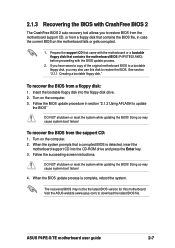
.... See section "2.1.1 Creating a bootable floppy disk." Doing so may cause system boot failure! Doing so may cause system boot failure! 4. ASUS P4PE-X/TE motherboard user guide 2-7 To recover the BIOS from a floppy disk: 1. Turn on the computer. 3. Follow the succeeding screen instructions. Turn on the computer. 2. Insert the bootable floppy disk into the CD...
.... See section "2.1.1 Creating a bootable floppy disk." Doing so may cause system boot failure! Doing so may cause system boot failure! 4. ASUS P4PE-X/TE motherboard user guide 2-7 To recover the BIOS from a floppy disk: 1. Turn on the computer. 3. Follow the succeeding screen instructions. Turn on the computer. 2. Insert the bootable floppy disk into the CD...

P4PE-X/TE User Manual
Page 40
Award BIOS Beep Codes Beep One short beep when displaying logo Long beeps in an endless loop One long beep followed by three short beeps High frequency beeps when system is working Meaning No error during POST No DRAM installed or detected Video card not found or video card memory bad CPU overheated; 2.1.4 BIOS beep codes When you turn the power on and the system runs POST (Power On Self Tests), you will hear BIOS beeps. System running at a lower frequency 2-8 Chapter 2: BIOS information Refer to the following table for the meaning of the beeps.
Award BIOS Beep Codes Beep One short beep when displaying logo Long beeps in an endless loop One long beep followed by three short beeps High frequency beeps when system is working Meaning No error during POST No DRAM installed or detected Video card not found or video card memory bad CPU overheated; 2.1.4 BIOS beep codes When you turn the power on and the system runs POST (Power On Self Tests), you will hear BIOS beeps. System running at a lower frequency 2-8 Chapter 2: BIOS information Refer to the following table for the meaning of the beeps.
P4PE-X/TE User Manual
Page 41
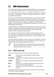
...this utility. Use this menu to change the configuration of your computer in section "2.1 Managing and updating your BIOS." ASUS P4PE-X/TE motherboard user guide 2-9 2.2 BIOS Setup program This motherboard supports a programmable Flash ROM that the computer can recognize these changes and record them in.... If you can also restart by pressing the reset button on . The Setup program is constantly being updated, the following BIOS setup screens and descriptions are installing a motherboard, reconfiguring your system, or prompted to enter the Setup utility, otherwise, POST continues...
...this utility. Use this menu to change the configuration of your computer in section "2.1 Managing and updating your BIOS." ASUS P4PE-X/TE motherboard user guide 2-9 2.2 BIOS Setup program This motherboard supports a programmable Flash ROM that the computer can recognize these changes and record them in.... If you can also restart by pressing the reset button on . The Setup program is constantly being updated, the following BIOS setup screens and descriptions are installing a motherboard, reconfiguring your system, or prompted to enter the Setup utility, otherwise, POST continues...

P4PE-X/TE User Manual
Page 42
...or Down arrow - (minus key) + (plus key) or spacebar or or Function Description Displays the General Help screen from anywhere in the BIOS Setup Jumps to the Exit menu or returns to the main menu from any menu by simply pressing or the + combination. The following table ...the values for the highlighted field Scrolls forward through the various setup menus. To exit the help window, press or . 2-10 Chapter 2: BIOS information The keys in the legend bar with their corresponding functions. The General Help screen lists the legend keys and their corresponding functions. Scroll ...
...or Down arrow - (minus key) + (plus key) or spacebar or or Function Description Displays the General Help screen from anywhere in the BIOS Setup Jumps to the Exit menu or returns to the main menu from any menu by simply pressing or the + combination. The following table ...the values for the highlighted field Scrolls forward through the various setup menus. To exit the help window, press or . 2-10 Chapter 2: BIOS information The keys in the legend bar with their corresponding functions. The General Help screen lists the legend keys and their corresponding functions. Scroll ...


