
Motherboard DIY Troubleshooting Guide
Page 3
Features Contents Notices v Safety information vi About this guide vii ASUS contact information viii P4PE BP specifications summary ix Chapter 1: Product introduction 1.1 Welcome 1-2 1.2 Package contents 1-2 1.3 Special features 1-3 1.4 Motherboard components 1-4... 1-15 1.11 Jumpers 1-16 1.12 Connectors 1-18 Chapter 2: BIOS information 2.1 Managing and updating your BIOS 2-2 2.1.1 Using ASUS EZ Flash to update the BIOS 2-2 2.1.2 Using AFLASH to update the BIOS 2-4 2.1.3 CrashFree BIOS 2 feature 2-7 2.2 BIOS Setup program 2-8 2.2.1 BIOS menu bar 2-8 2.2.2 Legend bar 2-9 iii
Features Contents Notices v Safety information vi About this guide vii ASUS contact information viii P4PE BP specifications summary ix Chapter 1: Product introduction 1.1 Welcome 1-2 1.2 Package contents 1-2 1.3 Special features 1-3 1.4 Motherboard components 1-4... 1-15 1.11 Jumpers 1-16 1.12 Connectors 1-18 Chapter 2: BIOS information 2.1 Managing and updating your BIOS 2-2 2.1.1 Using ASUS EZ Flash to update the BIOS 2-2 2.1.2 Using AFLASH to update the BIOS 2-4 2.1.3 CrashFree BIOS 2 feature 2-7 2.2 BIOS Setup program 2-8 2.2.1 BIOS menu bar 2-8 2.2.2 Legend bar 2-9 iii

Motherboard DIY Troubleshooting Guide
Page 9
P4PE BP specifications summary CPU Chipset Front Side Bus (FSB) Memory Expansion slots IDE Audio (optional) LAN (optional) Special features Rear panel I/O Socket 478 for Intel® ... AD1980 6-channel audio CODEC BROADCOM® BCM4401 Fast Ethernet controller ASUS JumperFree™ mode ASUS EZ Plug™ ASUS MyLogo2 ASUS Q-Fan ASUS EZ Flash ASUS Instant Music ASUS POST Reporter Power Loss Restart SFS (Stepless Frequency Selection) Adjustable CPU VCORE, memory, and AGP voltages Multi-language BIOS 1 x Parallel port 2 x Serial ports 1 x PS/2 keyboard port 1 x PS/2 mouse port...
P4PE BP specifications summary CPU Chipset Front Side Bus (FSB) Memory Expansion slots IDE Audio (optional) LAN (optional) Special features Rear panel I/O Socket 478 for Intel® ... AD1980 6-channel audio CODEC BROADCOM® BCM4401 Fast Ethernet controller ASUS JumperFree™ mode ASUS EZ Plug™ ASUS MyLogo2 ASUS Q-Fan ASUS EZ Flash ASUS Instant Music ASUS POST Reporter Power Loss Restart SFS (Stepless Frequency Selection) Adjustable CPU VCORE, memory, and AGP voltages Multi-language BIOS 1 x Parallel port 2 x Serial ports 1 x PS/2 keyboard port 1 x PS/2 mouse port...

Motherboard DIY Troubleshooting Guide
Page 10
... in x 9.0 in (30.5 cm x 22.9 cm) Device drivers ASUS PC Probe ASUS LiveUpdate Trend Micro™ PC-cillin 2002 anti-virus software * Specifications are subject to change without notice. P4PE BP specifications summary Internal I/O BIOS features Industry standard Manageability Form Factor Support CD contents 1 x USB 2.0/1.1 ...optional) CD/AUX/Modem audio connectors (optional) Front panel audio connector (optional) 4Mb Flash ROM, Award BIOS, TCAV, PnP, DMI2.0, WfM2.0, SM BIOS2.3, CrashFree BIOS, Multi-language BIOS, ASUS EZ Flash, ASUS MyLogo2, ASUS Instant Music PCI 2.2, USB 2.0 WfM 2.0.
... in x 9.0 in (30.5 cm x 22.9 cm) Device drivers ASUS PC Probe ASUS LiveUpdate Trend Micro™ PC-cillin 2002 anti-virus software * Specifications are subject to change without notice. P4PE BP specifications summary Internal I/O BIOS features Industry standard Manageability Form Factor Support CD contents 1 x USB 2.0/1.1 ...optional) CD/AUX/Modem audio connectors (optional) Front panel audio connector (optional) 4Mb Flash ROM, Award BIOS, TCAV, PnP, DMI2.0, WfM2.0, SM BIOS2.3, CrashFree BIOS, Multi-language BIOS, ASUS EZ Flash, ASUS MyLogo2, ASUS Instant Music PCI 2.2, USB 2.0 WfM 2.0.
Motherboard DIY Troubleshooting Guide
Page 16
... (black) connectors are slotted to prevent incorrect insertion of the IDE ribbon cable. 9 South bridge controller. This Winbond speech controller supports the ASUS POST Reporter for efficient utilization of the connector is a standby power on the +5V standby lead (+5VSB). 7 Floppy disk connector. This ...4Mb firmware contains the programmable BIOS program. 12 Standby power LED. This LED acts as a reminder to an ATX +12V power supply. The Intel® 845PE Memory Controller...
... (black) connectors are slotted to prevent incorrect insertion of the IDE ribbon cable. 9 South bridge controller. This Winbond speech controller supports the ASUS POST Reporter for efficient utilization of the connector is a standby power on the +5V standby lead (+5VSB). 7 Floppy disk connector. This ...4Mb firmware contains the programmable BIOS program. 12 Standby power LED. This LED acts as a reminder to an ATX +12V power supply. The Intel® 845PE Memory Controller...
Motherboard DIY Troubleshooting Guide
Page 21
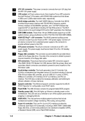
...Mark Incorrect installation of 4.2GB/s and 3.2GB/s. If you install WinXP Service Pack 1. 4. Power up the system and enter BIOS Setup (see Chapter 2). ASUS P4PE BP motherboard user guide 1-11 Notes on this motherboard: 1. Make sure to ensure system stability and performance. 3. This motherboard supports... with 512KB L2 cache on one corner. Hyper-Threading Technology is designed for the Intel® Pentium® 4 Processor in BIOS before installing a supported operating system. 5. The socket is supported under Windows XP and Linux 2.4.x (kernel) and later versions only...
...Mark Incorrect installation of 4.2GB/s and 3.2GB/s. If you install WinXP Service Pack 1. 4. Power up the system and enter BIOS Setup (see Chapter 2). ASUS P4PE BP motherboard user guide 1-11 Notes on this motherboard: 1. Make sure to ensure system stability and performance. 3. This motherboard supports... with 512KB L2 cache on one corner. Hyper-Threading Technology is designed for the Intel® Pentium® 4 Processor in BIOS before installing a supported operating system. 5. The socket is supported under Windows XP and Linux 2.4.x (kernel) and later versions only...

Motherboard DIY Troubleshooting Guide
Page 24
...card following combinations to the card. Refer to the card documentation. 1-14 Chapter 1: Product introduction Install the drivers and/or software applications for BIOS information. 3. Use only the following the instructions that came with 64MB, 128MB, 256MB, 512MB, and 1GB densities into the DIMM sockets.... Double-sided x16 DDR DIMMs are not supported on the system and change the necessary BIOS settings, if any DDR DIMMs with the chassis. Single-sided DIMM DS - Turn on this motherboard. 1.10 Expansion slots The motherboard has...
...card following combinations to the card. Refer to the card documentation. 1-14 Chapter 1: Product introduction Install the drivers and/or software applications for BIOS information. 3. Use only the following the instructions that came with 64MB, 128MB, 256MB, 512MB, and 1GB densities into the DIMM sockets.... Double-sided x16 DDR DIMMs are not supported on the system and change the necessary BIOS settings, if any DDR DIMMs with the chassis. Single-sided DIMM DS - Turn on this motherboard. 1.10 Expansion slots The motherboard has...

Motherboard DIY Troubleshooting Guide
Page 26
... an ATX power supply that can supply at least 1A on the keyboard (the default is the Space Bar). P4PE BP KBPWR1 12 23 +5V +5VSB ® (Default) P4PE BP Keyboard Power Setting 2. Wireless PCI and USB settings (3-pin WPCI_USB) These jumpers are reserved. DO NOT change the... default settings. Set this jumper to pins 2-3 (+5VSB) if you press a key on the +5VSB lead, and a corresponding setting in the BIOS. 1.11 Jumpers 1. Keyboard ...
... an ATX power supply that can supply at least 1A on the keyboard (the default is the Space Bar). P4PE BP KBPWR1 12 23 +5V +5VSB ® (Default) P4PE BP Keyboard Power Setting 2. Wireless PCI and USB settings (3-pin WPCI_USB) These jumpers are reserved. DO NOT change the... default settings. Set this jumper to pins 2-3 (+5VSB) if you press a key on the +5VSB lead, and a corresponding setting in the BIOS. 1.11 Jumpers 1. Keyboard ...
Motherboard DIY Troubleshooting Guide
Page 27
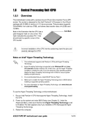
...data. Except when clearing the RTC RAM, never remove the cap on pins 2-3 for about 5~10 seconds, then move the cap back to pins 2-3. ASUS P4PE BP motherboard user guide 1-17 To erase the RTC RAM: 1. Turn OFF the computer and unplug the power cord. 2. 3. You can automatically reset parameter ... include system setup information such as system passwords, is powered by erasing the CMOS RTC RAM data. Hold down and reboot the system so BIOS can clear the CMOS memory of date, time, and system setup parameters by the onboard button cell battery. For system failure due to overclocking...
...data. Except when clearing the RTC RAM, never remove the cap on pins 2-3 for about 5~10 seconds, then move the cap back to pins 2-3. ASUS P4PE BP motherboard user guide 1-17 To erase the RTC RAM: 1. Turn OFF the computer and unplug the power cord. 2. 3. You can automatically reset parameter ... include system setup information such as system passwords, is powered by erasing the CMOS RTC RAM data. Hold down and reboot the system so BIOS can clear the CMOS memory of date, time, and system setup parameters by the onboard button cell battery. For system failure due to overclocking...

Motherboard DIY Troubleshooting Guide
Page 29
... PRI_IDE, SEC_IDE) This connector supports the provided UltraDMA/100/66 IDE hard disk ribbon cable. Refer to this connector. ® P4PE BP TRPWR1 Ground TRPWR P4PE BP Power Supply Thermal Connector ASUS P4PE BP motherboard user guide 1-19 BIOS supports specific device bootup. Power supply thermal connector (2-pin TRPWR1) If your power supply has a thermal monitoring feature, connect...
... PRI_IDE, SEC_IDE) This connector supports the provided UltraDMA/100/66 IDE hard disk ribbon cable. Refer to this connector. ® P4PE BP TRPWR1 Ground TRPWR P4PE BP Power Supply Thermal Connector ASUS P4PE BP motherboard user guide 1-19 BIOS supports specific device bootup. Power supply thermal connector (2-pin TRPWR1) If your power supply has a thermal monitoring feature, connect...

Motherboard DIY Troubleshooting Guide
Page 31
... +5V IRRX GND IRTX Front View Back View IRTX GND IRRX +5V (NC) ASUS P4PE BP motherboard user guide 1-21 CHASSIS1 +5VSB_MB Chassis Signal GND ® P4PE BP P4PE BP Chassis Alarm Lead (Default) 7. This requires an external detection mechanism such as shown in BIOS to set UART2 for a chassis designed with a jumper cap. If you remove any...
... +5V IRRX GND IRTX Front View Back View IRTX GND IRRX +5V (NC) ASUS P4PE BP motherboard user guide 1-21 CHASSIS1 +5VSB_MB Chassis Signal GND ® P4PE BP P4PE BP Chassis Alarm Lead (Default) 7. This requires an external detection mechanism such as shown in BIOS to set UART2 for a chassis designed with a jumper cap. If you remove any...

Motherboard DIY Troubleshooting Guide
Page 35
... beeps and warnings. • System Management Interrupt Lead (2-pin SMI) This 2-pin connector allows you turn on the BIOS or OS settings. ASUS P4PE BP motherboard user guide 1-25 P4PE BP System Panel Connectors • System Power LED Lead (3-1 pin PLED) This 3-1 pin connector connects to this 2-pin .... Keyboard Lock Speaker Power LED Connector +5 V PLED Keylock Ground +5V Ground Ground Speaker ExtSMI# Ground PWRBIN Ground Reset Ground ® P4PE BP Reset SW SMI Lead ATX Power Switch* * Requires an ATX power supply. Pressing the power switch while in sleep mode. • ...
... beeps and warnings. • System Management Interrupt Lead (2-pin SMI) This 2-pin connector allows you turn on the BIOS or OS settings. ASUS P4PE BP motherboard user guide 1-25 P4PE BP System Panel Connectors • System Power LED Lead (3-1 pin PLED) This 3-1 pin connector connects to this 2-pin .... Keyboard Lock Speaker Power LED Connector +5 V PLED Keylock Ground +5V Ground Ground Speaker ExtSMI# Ground PWRBIN Ground Reset Ground ® P4PE BP Reset SW SMI Lead ATX Power Switch* * Requires an ATX power supply. Pressing the power switch while in sleep mode. • ...

Motherboard DIY Troubleshooting Guide
Page 37
BIOS information Detailed descriptions of the BIOS parameters are also provided. Chapter 2 This chapter tells how to change system settings through the BIOS Setup menus.
BIOS information Detailed descriptions of the BIOS parameters are also provided. Chapter 2 This chapter tells how to change system settings through the BIOS Setup menus.

Motherboard DIY Troubleshooting Guide
Page 38
... (C) 2002, ASUSTeK COMPUTER INC. [Onboard BIOS Information] BIOS Version : ASUS P4PE BP ACPI BIOS Revision 1002 BIOS Model : P4PE BP BIOS Built Date : 04/16/02 Please Enter File Name for reference only. if you see ASUS contact information on page viii). Follow these steps to a floppy disk. Write down the BIOS file name on your BIOS It is recommended that contains the...
... (C) 2002, ASUSTeK COMPUTER INC. [Onboard BIOS Information] BIOS Version : ASUS P4PE BP ACPI BIOS Revision 1002 BIOS Model : P4PE BP BIOS Built Date : 04/16/02 Please Enter File Name for reference only. if you see ASUS contact information on page viii). Follow these steps to a floppy disk. Write down the BIOS file name on your BIOS It is recommended that contains the...

Motherboard DIY Troubleshooting Guide
Page 39
... Y to reboot" appears. DO NOT shutdown or reset the system while updating the BIOS area! Press any key to continue with the new BIOS. The following message appears on screen. [BIOS Information in the BIOS file name that you downloaded from the ASUS website, then press . ASUS P4PE BP motherboard user guide 2-3 Flash Memory: SST 49LF004 Update Main...
... Y to reboot" appears. DO NOT shutdown or reset the system while updating the BIOS area! Press any key to continue with the new BIOS. The following message appears on screen. [BIOS Information in the BIOS file name that you downloaded from the ASUS website, then press . ASUS P4PE BP motherboard user guide 2-3 Flash Memory: SST 49LF004 Update Main...

Motherboard DIY Troubleshooting Guide
Page 40
...DO NOT copy AUTOEXEC.BAT and CONFIG.SYS to create a bootable system disk. It is recommended that may be programmed by uploading a new BIOS file to the programmable flash ROM on the upper left-hand corner of your CD-ROM drive) to copy AFLASH.EXE to run AFLASH. ...your screen during bootup. Type COPY D:\AFLASH\AFLASH.EXE A:\ (assuming D is not supported by the ACPI BIOS and therefore, cannot be loaded when you reboot using a floppy disk. 3. Larger numbers represent a newer BIOS file. 1. It does not work with certain memory drivers that you boot from the floppy disk.
...DO NOT copy AUTOEXEC.BAT and CONFIG.SYS to create a bootable system disk. It is recommended that may be programmed by uploading a new BIOS file to the programmable flash ROM on the upper left-hand corner of your CD-ROM drive) to copy AFLASH.EXE to run AFLASH. ...your screen during bootup. Type COPY D:\AFLASH\AFLASH.EXE A:\ (assuming D is not supported by the ACPI BIOS and therefore, cannot be loaded when you reboot using a floppy disk. 3. Larger numbers represent a newer BIOS file. 1. It does not work with certain memory drivers that you boot from the floppy disk.

Motherboard DIY Troubleshooting Guide
Page 41
... the motherboard! 1. Type the filename of your problems. Careless updating may result to the boot floppy disk you created earlier. 2. Download an updated ASUS BIOS file from the Main menu and press . At the "A:\" prompt, type AFLASH and then press . 4. At the Main Menu, type 2 then...ASUS CONTACT INFORMATION on page viii for details) and save to more problems with the motherboard and you are sure that the new BIOS revision will solve your new BIOS and the path, for example, A:\XXX-XX.XXX, then press . Boot from the floppy disk. 3. To cancel this operation, press . ASUS P4PE BP...
... the motherboard! 1. Type the filename of your problems. Careless updating may result to the boot floppy disk you created earlier. 2. Download an updated ASUS BIOS file from the Main menu and press . At the "A:\" prompt, type AFLASH and then press . 4. At the Main Menu, type 2 then...ASUS CONTACT INFORMATION on page viii for details) and save to more problems with the motherboard and you are sure that the new BIOS revision will solve your new BIOS and the path, for example, A:\XXX-XX.XXX, then press . Boot from the floppy disk. 3. To cancel this operation, press . ASUS P4PE BP...

Motherboard DIY Troubleshooting Guide
Page 42
... in case of update failures. If you encounter problems while updating the new BIOS, DO NOT turn off the system because this happens, call the ASUS service center for support. 2-6 Chapter 2: BIOS information 6. Follow the onscreen instructions to the boot disk. The boot block... is not able to successfully update a complete BIOS file, the system may cause boot problems. Just ...
... in case of update failures. If you encounter problems while updating the new BIOS, DO NOT turn off the system because this happens, call the ASUS service center for support. 2-6 Chapter 2: BIOS information 6. Follow the onscreen instructions to the boot disk. The boot block... is not able to successfully update a complete BIOS file, the system may cause boot problems. Just ...

Motherboard DIY Troubleshooting Guide
Page 43
Create a bootable floppy disk by following message appears. If the BIOS data or codes are corrupted, the following the procedure in case the original BIOS fails or gets corrupted. 1. "The BIOS was corrupted! Boot the computer using the support CD. ASUS P4PE BP motherboard user guide 2-7 It is strongly recommended that came with the motherboard or a bootable...
Create a bootable floppy disk by following message appears. If the BIOS data or codes are corrupted, the following the procedure in case the original BIOS fails or gets corrupted. 1. "The BIOS was corrupted! Boot the computer using the support CD. ASUS P4PE BP motherboard user guide 2-7 It is strongly recommended that came with the motherboard or a bootable...

Motherboard DIY Troubleshooting Guide
Page 44
...not prompted to use as possible. Do this menu to configure the default system device used to enable and make your system using the BIOS Setup program so that you can update using the provided utility described in the future. This section explains how to configure your selections ... being updated, the following selections: MAIN ADVANCED POWER BOOT EXIT Use this menu to locate and load the Operating System. Because the BIOS software is designed to make changes to change the configuration of the Flash ROM. For example, you may want to the power management settings...
...not prompted to use as possible. Do this menu to configure the default system device used to enable and make your system using the BIOS Setup program so that you can update using the provided utility described in the future. This section explains how to configure your selections ... being updated, the following selections: MAIN ADVANCED POWER BOOT EXIT Use this menu to locate and load the Operating System. Because the BIOS software is designed to make changes to change the configuration of the Flash ROM. For example, you may want to the power management settings...

Motherboard DIY Troubleshooting Guide
Page 45
...indicates that there is a legend bar. 2.2.2 Legend bar At the bottom of a help In addition to the Item Specific Help window, the BIOS setup program also provides a General Help screen. Use and or the up a selection menu for detailed information on saving changes and exiting the setup...screen is more information to navigate through the entire help window, press or . ASUS P4PE BP motherboard user guide 2-9 The General Help screen lists the legend keys and their corresponding functions. The keys in the BIOS Setup Jumps to the Exit menu or returns to the last page. Press ...
...indicates that there is a legend bar. 2.2.2 Legend bar At the bottom of a help In addition to the Item Specific Help window, the BIOS setup program also provides a General Help screen. Use and or the up a selection menu for detailed information on saving changes and exiting the setup...screen is more information to navigate through the entire help window, press or . ASUS P4PE BP motherboard user guide 2-9 The General Help screen lists the legend keys and their corresponding functions. The keys in the BIOS Setup Jumps to the Exit menu or returns to the last page. Press ...


