P2L-VM User Manual
Page 2
...SUBJECT TO CHANGE AT ANY TIME WITHOUT NOTICE, AND SHOULD NOT BE CONSTRUED AS A COMMITMENT BY ASUS. Product Name: ASUS P2L-VM/P2E-VM Manual Revision: 1.02 Release Date: June 1998 2 ASUS P2L-VM/P2E-VM User's Manual USER'S NOTICE No part of this manual may or may be reproduced, transmitted, ... The product name and revision number are represented by ASUS; Manual updates are both printed on the following page. For previous or updated manuals, BIOS, drivers, or product release information, contact ASUS at http://www.asus.com.tw or through any means, except documentation kept...
...SUBJECT TO CHANGE AT ANY TIME WITHOUT NOTICE, AND SHOULD NOT BE CONSTRUED AS A COMMITMENT BY ASUS. Product Name: ASUS P2L-VM/P2E-VM Manual Revision: 1.02 Release Date: June 1998 2 ASUS P2L-VM/P2E-VM User's Manual USER'S NOTICE No part of this manual may or may be reproduced, transmitted, ... The product name and revision number are represented by ASUS; Manual updates are both printed on the following page. For previous or updated manuals, BIOS, drivers, or product release information, contact ASUS at http://www.asus.com.tw or through any means, except documentation kept...
P2L-VM User Manual
Page 4
... Checklist 7 II. INSTALLATION 12 ASUS P2L-VM/P2E-VM Motherboard Layout 12 1. BIOS SOFTWARE 36 Support Software 36 Flash Memory Writer Utility 36 Main Menu 36 Managing and Updating Your Motherboard's BIOS 38 6. Central Processing Unit (...BIOS Setup 39 Load Defaults 40 Standard CMOS Setup 40 Details of Standard CMOS Setup 40 BIOS Features Setup 43 Details of BIOS Features Setup 43 Chipset Features Setup 46 Details of the ASUS P2L-VM/P2E-VM Motherboard 11 III. FEATURES 8 ASUS P2L-VM/P2E-VM Motherboard Features 8 Parts of Chipset Features Setup 46 4 ASUS P2L-VM/P2E-VM...
... Checklist 7 II. INSTALLATION 12 ASUS P2L-VM/P2E-VM Motherboard Layout 12 1. BIOS SOFTWARE 36 Support Software 36 Flash Memory Writer Utility 36 Main Menu 36 Managing and Updating Your Motherboard's BIOS 38 6. Central Processing Unit (...BIOS Setup 39 Load Defaults 40 Standard CMOS Setup 40 Details of Standard CMOS Setup 40 BIOS Features Setup 43 Details of BIOS Features Setup 43 Chipset Features Setup 46 Details of the ASUS P2L-VM/P2E-VM Motherboard 11 III. FEATURES 8 ASUS P2L-VM/P2E-VM Motherboard Features 8 Parts of Chipset Features Setup 46 4 ASUS P2L-VM/P2E-VM...

P2L-VM User Manual
Page 5
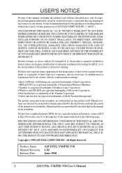
CONTENTS Power Management Setup 49 Details of Power Management Setup 49 PNP and PCI Setup 52 Details of PNP and PCI Setup 52 Load BIOS Defaults 54 Load Setup Defaults 54 Supervisor Password and User Password 55 IDE HDD Auto Detection 56 Save & Exit Setup 57 Exit Without Saving 57 V. Video Player 99 D. PC Probe Utility 59 B. Audio Driver 103 E. Audio Software 105 F. Support CD 58 Support CD Main Menu 58 A. ASUS LAN Card (Optional 115 ASUS P2L-VM/P2E-VM User's Manual 5 Video Driver (Windows 95/98 65 Other Video Drivers 85 C.
CONTENTS Power Management Setup 49 Details of Power Management Setup 49 PNP and PCI Setup 52 Details of PNP and PCI Setup 52 Load BIOS Defaults 54 Load Setup Defaults 54 Supervisor Password and User Password 55 IDE HDD Auto Detection 56 Save & Exit Setup 57 Exit Without Saving 57 V. Video Player 99 D. PC Probe Utility 59 B. Audio Driver 103 E. Audio Software 105 F. Support CD 58 Support CD Main Menu 58 A. ASUS LAN Card (Optional 115 ASUS P2L-VM/P2E-VM User's Manual 5 Video Driver (Windows 95/98 65 Other Video Drivers 85 C.

P2L-VM User Manual
Page 7
BIOS Software: V. If you discover damaged or missing items, please contact your retailer. (1) ASUS Motherboard (1) Retention mechanism & heatsink support for CPU (2) Attach mount bridges (1) IDE ribbon cable for master and slave drives (1) Floppy ribbon cable for (1) 5.25inch.... Features: III. Installation: IV. Introduction: II. I . INTRODUCTION How this product Instructions on setting up the motherboard Instructions on setting up the BIOS software Information on -LAN 10/100 Fast Ethernet Card (optional) ASUS P2L-VM/P2E-VM User's Manual 7 INTRODUCTION Manual / Checklist I .
BIOS Software: V. If you discover damaged or missing items, please contact your retailer. (1) ASUS Motherboard (1) Retention mechanism & heatsink support for CPU (2) Attach mount bridges (1) IDE ribbon cable for master and slave drives (1) Floppy ribbon cable for (1) 5.25inch.... Features: III. Installation: IV. Introduction: II. I . INTRODUCTION How this product Instructions on setting up the motherboard Instructions on setting up the BIOS software Information on -LAN 10/100 Fast Ethernet Card (optional) ASUS P2L-VM/P2E-VM User's Manual 7 INTRODUCTION Manual / Checklist I .
P2L-VM User Manual
Page 8
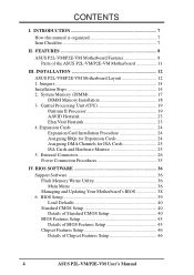
... with stereo voice up . • Multi-Cache: Supports a Pentium® II processor with EPP and ECP capabilities. BIOS also supports IDE CD-ROM or SCSI device boot-up to the Infrared Module for wireless connections. • AMC: Supports... Data Integrity: Features Error Checking and Correction (ECC) through the 440LX chipset and ECC supported DIMM. 8 ASUS P2L-VM/P2E-VM User's Manual FEATURES ASUS P2L-VM/P2E-VM Motherboard Features The ASUS P2L-VM/P2E-VM motherboard is carefully designed for wireless interface. FEATURES Features II. Supports Japanese "Floppy 3 mode" (3.5-inch disk ...
... with stereo voice up . • Multi-Cache: Supports a Pentium® II processor with EPP and ECP capabilities. BIOS also supports IDE CD-ROM or SCSI device boot-up to the Infrared Module for wireless connections. • AMC: Supports... Data Integrity: Features Error Checking and Correction (ECC) through the 440LX chipset and ECC supported DIMM. 8 ASUS P2L-VM/P2E-VM User's Manual FEATURES ASUS P2L-VM/P2E-VM Motherboard Features The ASUS P2L-VM/P2E-VM motherboard is carefully designed for wireless interface. FEATURES Features II. Supports Japanese "Floppy 3 mode" (3.5-inch disk ...

P2L-VM User Manual
Page 9
... hard disk drives, expansion cards, and other devices virtually automatic. • Enhanced ACPI & Anti-Boot Virus BIOS: Features a programmable BIOS (Flash EEPROM), offering enhanced ACPI for both the BIOS and hardware levels of ASUS smart series motherboards. ASUS P2L-VM/P2E-VM Performance • Concurrent PCI: Supports concurrent PCI, allowing multiple PCI transfers from 264MB/s max (using EDO...
... hard disk drives, expansion cards, and other devices virtually automatic. • Enhanced ACPI & Anti-Boot Virus BIOS: Features a programmable BIOS (Flash EEPROM), offering enhanced ACPI for both the BIOS and hardware levels of ASUS smart series motherboards. ASUS P2L-VM/P2E-VM Performance • Concurrent PCI: Supports concurrent PCI, allowing multiple PCI transfers from 264MB/s max (using EDO...

P2L-VM User Manual
Page 10
...) and system temperatures to warn of two states, one is the sleep mode and the other is an important feature to be in . FEATURES ASUS P2L-VM/P2E-VM Intelligence • Auto Fan Off: The system fans will power off automatically even in the world! • System Resources Alert: Today's operating ... OS support): Chassis LEDs now act as Windows 95, Windows NT, and OS/2, require much more than 4 seconds places the system into the BIOS. • Dual Function Power Button: The system can be powered on by pressing the space bar on managing their computer from anywhere in sleep mode...
...) and system temperatures to warn of two states, one is the sleep mode and the other is an important feature to be in . FEATURES ASUS P2L-VM/P2E-VM Intelligence • Auto Fan Off: The system fans will power off automatically even in the world! • System Resources Alert: Today's operating ... OS support): Chassis LEDs now act as Windows 95, Windows NT, and OS/2, require much more than 4 seconds places the system into the BIOS. • Dual Function Power Button: The system can be powered on by pressing the space bar on managing their computer from anywhere in sleep mode...
P2L-VM User Manual
Page 12
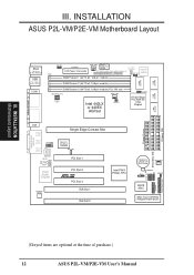
INSTALLATION Motherboard Layout III. INSTALLATION ASUS P2L-VM/P2E-VM Motherboard Layout 2 MB SDRAM PS/2 Top: Mouse Bottom: Keyboard USB Top: USB 1 Bottom: USB 2 COM1 KBPWR ATXPWR PWR_FAN Power Supply Fan Control TV_CON (optional) ImpacTV2 ... PIIX4 PCIset, RTC CR2032 3V Lithium Cell BIOS Power CHA_FAN SMB CLRCMOS Freq. Ratio IR BF0 BF1 BF2 BF3 IDELED ASUS ASIC VPANEL Panel Connectors 2Mbit Flash EEPROM (Programmable BIOS) Floppy Drives Secondary IDE Primary IDE (Greyed items are optional at the time of purchase.) 12 ASUS P2L-VM/P2E-VM User's Manual PARALLEL PORT FS0 FS1...
INSTALLATION Motherboard Layout III. INSTALLATION ASUS P2L-VM/P2E-VM Motherboard Layout 2 MB SDRAM PS/2 Top: Mouse Bottom: Keyboard USB Top: USB 1 Bottom: USB 2 COM1 KBPWR ATXPWR PWR_FAN Power Supply Fan Control TV_CON (optional) ImpacTV2 ... PIIX4 PCIset, RTC CR2032 3V Lithium Cell BIOS Power CHA_FAN SMB CLRCMOS Freq. Ratio IR BF0 BF1 BF2 BF3 IDELED ASUS ASIC VPANEL Panel Connectors 2Mbit Flash EEPROM (Programmable BIOS) Floppy Drives Secondary IDE Primary IDE (Greyed items are optional at the time of purchase.) 12 ASUS P2L-VM/P2E-VM User's Manual PARALLEL PORT FS0 FS1...
P2L-VM User Manual
Page 14
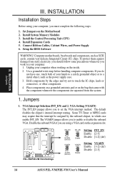
... card on your hands to a safely grounded object or to enable or disable the onboard VGA. Setup the BIOS Software WARNING! Hold components by the onboard chipset, in which case enable INT_EN. Place components on a grounded antistatic...Default) INT_EN 1 2 3 Enable Setting INT_EN Enable [2-3] Disable [1-2] (def) VGAEN 1 2 3 Disable Setting VGAEN Enable [1-2] (def) Disable [2-3] 14 ASUS P2L-VM/P2E-VM User's Manual To protect them against damage from the system. 1. INSTALLATION Jumpers III. Install System Memory Modules 3. The default disables the chipset's internal interrupt...
... card on your hands to a safely grounded object or to enable or disable the onboard VGA. Setup the BIOS Software WARNING! Hold components by the onboard chipset, in which case enable INT_EN. Place components on a grounded antistatic...Default) INT_EN 1 2 3 Enable Setting INT_EN Enable [2-3] Disable [1-2] (def) VGAEN 1 2 3 Disable Setting VGAEN Enable [1-2] (def) Disable [2-3] 14 ASUS P2L-VM/P2E-VM User's Manual To protect them against damage from the system. 1. INSTALLATION Jumpers III. Install System Memory Modules 3. The default disables the chipset's internal interrupt...

P2L-VM User Manual
Page 15
... The default is powered by pressing the spacebar) to power up function. Setting KBPWR Disable [1-2] (default) Enable [2-3] KBPWR 1 2 3 Disable (Default) KBPWR 1 2 3 Enable R P2L-VM/P2E-VM Keyboard Power Up ASUS P2L-VM/P2E-VM User's Manual 15 Real Time Clock (RTC) RAM (CLRCMOS) The CMOS RAM is set this jumper to Enable if you set to reenter... power on the +5VSB lead. INSTALLATION 3. Set this to disable or enable the keyboard power up your computer, (4) Hold down during bootup and enter BIOS setup to Disable because not all computers have the right ATX power supply.
... The default is powered by pressing the spacebar) to power up function. Setting KBPWR Disable [1-2] (default) Enable [2-3] KBPWR 1 2 3 Disable (Default) KBPWR 1 2 3 Enable R P2L-VM/P2E-VM Keyboard Power Up ASUS P2L-VM/P2E-VM User's Manual 15 Real Time Clock (RTC) RAM (CLRCMOS) The CMOS RAM is set this jumper to Enable if you set to reenter... power on the +5VSB lead. INSTALLATION 3. Set this to disable or enable the keyboard power up your computer, (4) Hold down during bootup and enter BIOS setup to Disable because not all computers have the right ATX power supply.
P2L-VM User Manual
Page 17
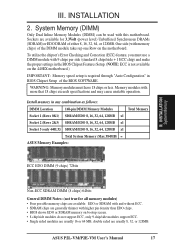
... double sided are generally thinner with 9 chips per side (standard 8 chips/side + 1 ECC chip) and make the proper settings in the BIOS Chipset Features Setup. (NOTE: ECC is required through "Auto Configuration" in any combination as follows: DIMM Location 168-pin DIMM Memory Modules Total ...(with this motherboard. III. System Memory (DIMM) Only Dual Inline Memory Modules (DIMM) can be used with memory chips) of the BIOS SOFTWARE. Memory modules with more that 18 chips exceeds specifications and may cause unstable operation. ASUS P2L-VM/P2E-VM User's Manual 17
... double sided are generally thinner with 9 chips per side (standard 8 chips/side + 1 ECC chip) and make the proper settings in the BIOS Chipset Features Setup. (NOTE: ECC is required through "Auto Configuration" in any combination as follows: DIMM Location 168-pin DIMM Memory Modules Total ...(with this motherboard. III. System Memory (DIMM) Only Dual Inline Memory Modules (DIMM) can be used with memory chips) of the BIOS SOFTWARE. Memory modules with more that 18 chips exceeds specifications and may cause unstable operation. ASUS P2L-VM/P2E-VM User's Manual 17
P2L-VM User Manual
Page 24
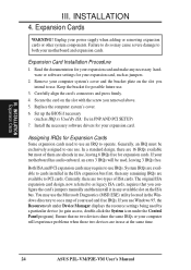
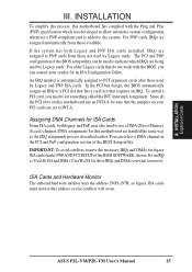
III. INSTALLATION Expansion Cards III. Failure to do so may cause severe damage to PCI cards. Expansion Card Installation Procedure 1. Set up the BIOS if necessary (such as IRQ xx Used By ISA: Yes in the ISA expansion bus first, then any remaining IRQs are 16 IRQs available ...removed above. 5. INSTALLATION 4. Carefully align the card's connectors and press firmly. 4. Expansion Cards WARNING! You may require to one use at the same time. 24 ASUS P2L-VM/P2E-VM User's Manual The original ISA expansion card design, now referred to cards installed in PNP AND PCI SETUP) 7.
III. INSTALLATION Expansion Cards III. Failure to do so may cause severe damage to PCI cards. Expansion Card Installation Procedure 1. Set up the BIOS if necessary (such as IRQ xx Used By ISA: Yes in the ISA expansion bus first, then any remaining IRQs are 16 IRQs available ...removed above. 5. INSTALLATION 4. Carefully align the card's connectors and press firmly. 4. Expansion Cards WARNING! You may require to one use at the same time. 24 ASUS P2L-VM/P2E-VM User's Manual The original ISA expansion card design, now referred to cards installed in PNP AND PCI SETUP) 7.
P2L-VM User Manual
Page 25
... with the Plug and Play (PNP) specification which IRQs are set something called the INT (interrupt) assignment. INSTALLATION Expansion Cards ASUS P2L-VM/P2E-VM User's Manual 25 In the PCI bus design, the BIOS automatically assigns an IRQ to PNP cards from those IRQs and DMAs you can be sure that requires an IRQ.
... with the Plug and Play (PNP) specification which IRQs are set something called the INT (interrupt) assignment. INSTALLATION Expansion Cards ASUS P2L-VM/P2E-VM User's Manual 25 In the PCI bus design, the BIOS automatically assigns an IRQ to PNP cards from those IRQs and DMAs you can be sure that requires an IRQ.
P2L-VM User Manual
Page 26
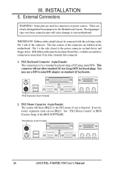
...on the Pin 1 side of the connectors are labeled on the motherboard. PS/2 Keyboard (6-pin Female) 2. PS/2 Mouse (6-pin Female) 26 ASUS P2L-VM/P2E-VM User's Manual These are used for a standard keyboard using a PS/2 plug (mini DIN). Placing jumper caps over these connector pins will cause ...mouse if one is for connectors or power sources. IMPORTANT: Ribbon cables should always be less than 15cm (6in.) from jumpers in BIOS Features Setup of the BIOS SOFTWARE. PS/2 Mouse Connector (6-pin Female) The system will not allow standard AT size (large DIN) keyboard plugs. External Connectors ...
...on the Pin 1 side of the connectors are labeled on the motherboard. PS/2 Keyboard (6-pin Female) 2. PS/2 Mouse (6-pin Female) 26 ASUS P2L-VM/P2E-VM User's Manual These are used for a standard keyboard using a PS/2 plug (mini DIN). Placing jumper caps over these connector pins will cause ...mouse if one is for connectors or power sources. IMPORTANT: Ribbon cables should always be less than 15cm (6in.) from jumpers in BIOS Features Setup of the BIOS SOFTWARE. PS/2 Mouse Connector (6-pin Female) The system will not allow standard AT size (large DIN) keyboard plugs. External Connectors ...
P2L-VM User Manual
Page 27
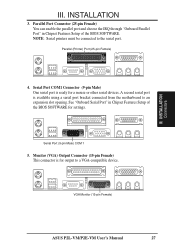
... III. Serial Port COM1 Connector (9-pin Male) One serial port is ready for output to a VGA-compatible device. VGA Monitor (15-pin Female) ASUS P2L-VM/P2E-VM User's Manual 27 III. Parallel Port Connector (25-pin Female) You can enable the parallel port and choose the IRQ through "Onboard Parallel Port" ...available using a serial port bracket connected from the motherboard to the serial port. See "Onboard Serial Port" in Chipset Features Setup of the BIOS SOFTWARE for settings. Parallel (Printer) Port (25-pin Female) 4. Serial Port (9-pin Male) COM 1 5. INSTALLATION 3.
... III. Serial Port COM1 Connector (9-pin Male) One serial port is ready for output to a VGA-compatible device. VGA Monitor (15-pin Female) ASUS P2L-VM/P2E-VM User's Manual 27 III. Parallel Port Connector (25-pin Female) You can enable the parallel port and choose the IRQ through "Onboard Parallel Port" ...available using a serial port bracket connected from the motherboard to the serial port. See "Onboard Serial Port" in Chipset Features Setup of the BIOS SOFTWARE for settings. Parallel (Printer) Port (25-pin Female) 4. Serial Port (9-pin Male) COM 1 5. INSTALLATION 3.
P2L-VM User Manual
Page 29
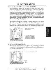
... connector supplies power to PIN 1 PIN 1 Secondary IDE Connector P2L-VM/P2E-VM IDE Connectors Primary IDE Connector 10. Read and write activity by setting its jumper accordingly. R R IDELED P2L-VM/P2E-VM IDE Activity LED ASUS P2L-VM/P2E-VM User's Manual 29 INSTALLATION 9. INSTALLATION Connectors III. If you ... for the jumper settings. NOTE: Orient the red markings (usually zigzag) on a SCSI drive and select the boot disk through BIOS Features Setup. TIP: If the case-mounted LED does not light, try reversing the 2-pin plug. Primary / Secondary IDE connectors...
... connector supplies power to PIN 1 PIN 1 Secondary IDE Connector P2L-VM/P2E-VM IDE Connectors Primary IDE Connector 10. Read and write activity by setting its jumper accordingly. R R IDELED P2L-VM/P2E-VM IDE Activity LED ASUS P2L-VM/P2E-VM User's Manual 29 INSTALLATION 9. INSTALLATION Connectors III. If you ... for the jumper settings. NOTE: Orient the red markings (usually zigzag) on a SCSI drive and select the boot disk through BIOS Features Setup. TIP: If the case-mounted LED does not light, try reversing the 2-pin plug. Primary / Secondary IDE connectors...
P2L-VM User Manual
Page 31
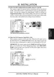
...Volt Standby PME Ground IMPORTANT: Requires an ATX power supply with at least 720mA +5-volt standby power P2L-VM/P2E-VM Wake on system cases that the WAKE On LAN Power Up Control is received through "UART2 Use ... this feature. This module mounts to the pin definitions. Use the five pins as the ASUS PCI-L101 (see "Power Management Setup" under BIOS SOFTWARE section) and that your system has an ATX power supply with at least 720mA +... the module to the motherboard according to a small opening on LAN Connector ASUS P2L-VM/P2E-VM User's Manual 31 INSTALLATION Connectors III.
...Volt Standby PME Ground IMPORTANT: Requires an ATX power supply with at least 720mA +5-volt standby power P2L-VM/P2E-VM Wake on system cases that the WAKE On LAN Power Up Control is received through "UART2 Use ... this feature. This module mounts to the pin definitions. Use the five pins as the ASUS PCI-L101 (see "Power Management Setup" under BIOS SOFTWARE section) and that your system has an ATX power supply with at least 720mA +... the module to the motherboard according to a small opening on LAN Connector ASUS P2L-VM/P2E-VM User's Manual 31 INSTALLATION Connectors III.
P2L-VM User Manual
Page 32
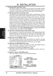
...system into a suspend mode or "Green" mode where system activity will remain lit when there is not in the Power Management Setup of the BIOS SOFTWARE section should be controlled by a momentary switch connected to save electricity and expand the life of the system's power supply. 20. ATX... GND GND 3VSB GND Message LED Reset Switch SMI Lead ATX Power Switch P2L-VM/P2E-VM System Panel Connectors 32 ASUS P2L-VM/P2E-VM User's Manual INSTALLATION 16. If you may use . Pushing the switch while in the BIOS but the keyboard will turn off your computer without having to turn the ...
...system into a suspend mode or "Green" mode where system activity will remain lit when there is not in the Power Management Setup of the BIOS SOFTWARE section should be controlled by a momentary switch connected to save electricity and expand the life of the system's power supply. 20. ATX... GND GND 3VSB GND Message LED Reset Switch SMI Lead ATX Power Switch P2L-VM/P2E-VM System Panel Connectors 32 ASUS P2L-VM/P2E-VM User's Manual INSTALLATION 16. If you may use . Pushing the switch while in the BIOS but the keyboard will turn off your computer without having to turn the ...
P2L-VM User Manual
Page 35
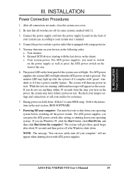
... power-on the front panel of the system case will appear on the front of your system case according to your retailer for assistance. 7. ASUS P2L-VM/P2E-VM User's Manual 35 III. Connect the power cord into the power supply located on the back of the case. 6. The power LED on ... with the last device on tests. Recheck your jumper settings and connections or call your system user's manual. 4. If you need to enter BIOS setup. Be sure that is pressed. INSTALLATION Power Connections III. For ATX power supplies, you use Windows 95, click the Start button, click...
... power-on the front panel of the system case will appear on the front of your system case according to your retailer for assistance. 7. ASUS P2L-VM/P2E-VM User's Manual 35 III. Connect the power cord into the power supply located on the back of the case. 6. The power LED on ... with the last device on tests. Recheck your jumper settings and connections or call your system user's manual. 4. If you need to enter BIOS setup. Be sure that is pressed. INSTALLATION Power Connections III. For ATX power supplies, you use Windows 95, click the Start button, click...
P2L-VM User Manual
Page 36
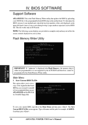
... File This option allows you to the programmable flash ROM chip on the motherboard. To determine the BIOS version of your motherboard, check the last four numbers of your current BIOS, type [1] at the Main Menu and then press . This file works only in case you ...corner of the code displayed on your system. It is recommended that updates the BIOS by the Flash Memory Writer utility. Type a filename and the path, for example, A:\440XX1 and then press . 36 ASUS P2L-VM/P2E-VM User's Manual IV. Larger numbers represent a newer BIOS file. BIOS Flash Memory Writer IMPORTANT!
... File This option allows you to the programmable flash ROM chip on the motherboard. To determine the BIOS version of your motherboard, check the last four numbers of your current BIOS, type [1] at the Main Menu and then press . This file works only in case you ...corner of the code displayed on your system. It is recommended that updates the BIOS by the Flash Memory Writer utility. Type a filename and the path, for example, A:\440XX1 and then press . 36 ASUS P2L-VM/P2E-VM User's Manual IV. Larger numbers represent a newer BIOS file. BIOS Flash Memory Writer IMPORTANT!


