P2B-VM User Manual
Page 2
... or missing. For previous or updated manuals, BIOS, drivers, or product release information, contact ASUS at http://www.asus.com.tw or through any means, except documentation kept by the third digit in the manual revision number. Product Name: ASUS P2B-VM Manual Revision: 1.04 E295 Release Date: November 1998 2 ASUS P2B-VM User's Manual Copyright © 1998 ASUSTeK...
... or missing. For previous or updated manuals, BIOS, drivers, or product release information, contact ASUS at http://www.asus.com.tw or through any means, except documentation kept by the third digit in the manual revision number. Product Name: ASUS P2B-VM Manual Revision: 1.04 E295 Release Date: November 1998 2 ASUS P2B-VM User's Manual Copyright © 1998 ASUSTeK...

P2B-VM User Manual
Page 4
... IRQs for Expansion Cards 24 Assigning DMA Channels for Slot 1 Processors 23 4. FEATURES 8 Features of the ASUS P2B-VM Motherboard 8 Parts of Power Management Setup 49 4 ASUS P2B-VM User's Manual BIOS Setup 39 Load Defaults 40 Standard CMOS Setup 40 Details of Standard CMOS Setup 40... BIOS Features Setup 43 Details of BIOS Features Setup 43 Chipset Features Setup 46 Details of Chipset Features Setup 46 Power Management Setup 49 Details of the ASUS P2B-VM Motherboard 11 III. External Connectors 26 Power Connection...
... IRQs for Expansion Cards 24 Assigning DMA Channels for Slot 1 Processors 23 4. FEATURES 8 Features of the ASUS P2B-VM Motherboard 8 Parts of Power Management Setup 49 4 ASUS P2B-VM User's Manual BIOS Setup 39 Load Defaults 40 Standard CMOS Setup 40 Details of Standard CMOS Setup 40... BIOS Features Setup 43 Details of BIOS Features Setup 43 Chipset Features Setup 46 Details of Chipset Features Setup 46 Power Management Setup 49 Details of the ASUS P2B-VM Motherboard 11 III. External Connectors 26 Power Connection...

P2B-VM User Manual
Page 5
Other Video Drivers 65 C. Software Wavetable 92 G. ATI Player 77 D. DMI Utility 93 ASUS P2B-VM User's Manual 5 CONTENTS PNP and PCI Setup 52 Details of PNP and PCI Setup 52 Load BIOS Defaults 54 Load Setup Defaults 54 Supervisor Password and User Password 55 IDE HDD Auto Detection 56 Save & Exit Setup 57 Exit Without Saving 57 V. Audio Driver 81 E. Video Driver 61 B. SUPPORT CD 58 ASUS Support CD Main Menu 58 A. Audio Software 85 F.
Other Video Drivers 65 C. Software Wavetable 92 G. ATI Player 77 D. DMI Utility 93 ASUS P2B-VM User's Manual 5 CONTENTS PNP and PCI Setup 52 Details of PNP and PCI Setup 52 Load BIOS Defaults 54 Load Setup Defaults 54 Supervisor Password and User Password 55 IDE HDD Auto Detection 56 Save & Exit Setup 57 Exit Without Saving 57 V. Audio Driver 81 E. Video Driver 61 B. SUPPORT CD 58 ASUS Support CD Main Menu 58 A. Audio Software 85 F.

P2B-VM User Manual
Page 7
... How this product Instructions on setting up the motherboard Instructions on setting up the BIOS software Information on the included support software Item Checklist Please check that your retailer. (1) ASUS Motherboard (1) Universal Retention Mechanism for SECC/SECC2/SEPP (1) IDE ribbon cable for ... User's Manual COM2 connector with bracket (optional) ASUS PC100 DIMM memory module (optional) ASUS PCI-L101 Wake-On-LAN 10/100 Fast Ethernet Card (optional) IrDA-compliant infrared module (optional) ASUS P2B-VM User's Manual 7 BIOS Software: V. If you discover damaged or missing items...
... How this product Instructions on setting up the motherboard Instructions on setting up the BIOS software Information on the included support software Item Checklist Please check that your retailer. (1) ASUS Motherboard (1) Universal Retention Mechanism for SECC/SECC2/SEPP (1) IDE ribbon cable for ... User's Manual COM2 connector with bracket (optional) ASUS PC100 DIMM memory module (optional) ASUS PCI-L101 Wake-On-LAN 10/100 Fast Ethernet Card (optional) IrDA-compliant infrared module (optional) ASUS P2B-VM User's Manual 7 BIOS Software: V. If you discover damaged or missing items...

P2B-VM User Manual
Page 9
... setup of hard disk drives, expansion cards, and other devices virtually automatic. • PC'98 Compliant: Both the BIOS and hardware levels of ASUS smart series of most devices for your motherboard against boot sector viruses through boot firmware (Anti-Boot Virus... to communicate within a standard protocol creating a higher level of compatibility. (Requires DMI-enabled components.) • Easy Installation: Incorporates BIOS that this new technology is compatible with Intel chipsets improves IDE transfer rate using SDRAM. ASUS P2B-VM User's Manual 9 FEATURES Features II.
... setup of hard disk drives, expansion cards, and other devices virtually automatic. • PC'98 Compliant: Both the BIOS and hardware levels of ASUS smart series of most devices for your motherboard against boot sector viruses through boot firmware (Anti-Boot Virus... to communicate within a standard protocol creating a higher level of compatibility. (Requires DMI-enabled components.) • Easy Installation: Incorporates BIOS that this new technology is compatible with Intel chipsets improves IDE transfer rate using SDRAM. ASUS P2B-VM User's Manual 9 FEATURES Features II.

P2B-VM User Manual
Page 10
...8226; Message LED (requires ACPI OS support): Turbo LEDs now act as Windows 95/98/ NT and OS/2, require much more efficiently. 10 ASUS P2B-VM User's Manual With this benefit on managing their computer from anywhere in . Suggestions will warn the user before the system resources are used up to...pressed for less than 4 seconds, the system enters the soft-off automatically even in the working state places the system into one of the BIOS setting. • Keyboard Power Up: Keyboard Power Up can be enabled or disabled to allow the computer to present enormous user interfaces and...
...8226; Message LED (requires ACPI OS support): Turbo LEDs now act as Windows 95/98/ NT and OS/2, require much more efficiently. 10 ASUS P2B-VM User's Manual With this benefit on managing their computer from anywhere in . Suggestions will warn the user before the system resources are used up to...pressed for less than 4 seconds, the system enters the soft-off automatically even in the working state places the system into one of the BIOS setting. • Keyboard Power Up: Keyboard Power Up can be enabled or disabled to allow the computer to present enormous user interfaces and...

P2B-VM User Manual
Page 12
INSTALLATION ASUS P2B-VM Motherboard Layout PARALLEL PORT ATXPWR CPU Slot 1 DIMM Socket 1 (64/72 bit, 168 pin module) DIMM Socket 2 (64/72 bit, 168 pin module) DIMM Socket 3 (... VGAEN CLRTC CR2032 3V Lithium Cell (BIOSPower) FREQ MULT BF0 BF1 BF2 BF3 WOL_CON ASUS ASIC IR Flash EEPROM (Programable BIOS) GAME/AUDIO (optional) (Grayed items are optional at the time of purchase.) R FLOPPY SECONDARY IDE PRIMARY IDE Panel Connectors VPANEL 12 ASUS P2B-VM User's Manual ATI Multimedia Connector III. INSTALLATION Motherboard Layout III.
INSTALLATION ASUS P2B-VM Motherboard Layout PARALLEL PORT ATXPWR CPU Slot 1 DIMM Socket 1 (64/72 bit, 168 pin module) DIMM Socket 2 (64/72 bit, 168 pin module) DIMM Socket 3 (... VGAEN CLRTC CR2032 3V Lithium Cell (BIOSPower) FREQ MULT BF0 BF1 BF2 BF3 WOL_CON ASUS ASIC IR Flash EEPROM (Programable BIOS) GAME/AUDIO (optional) (Grayed items are optional at the time of purchase.) R FLOPPY SECONDARY IDE PRIMARY IDE Panel Connectors VPANEL 12 ASUS P2B-VM User's Manual ATI Multimedia Connector III. INSTALLATION Motherboard Layout III.

P2B-VM User Manual
Page 14
... Unit (CPU) 4. Setup the BIOS Software WARNING! Use a grounded wrist strap before handling computer components. Jumpers 1. The default disables the chipset's internal interrupt routing. Disable the onboard VGA if you work on the inside. 2. R P2B-VM VGA Settings VGAEN 1 2 3 Enable (Default) INT_EN 1 2 3 Disable (Default) VGAEN 1 2 3 Disable INT_EN 1 2 3 Enable 14 ASUS P2B-VM User's Manual To protect...
... Unit (CPU) 4. Setup the BIOS Software WARNING! Use a grounded wrist strap before handling computer components. Jumpers 1. The default disables the chipset's internal interrupt routing. Disable the onboard VGA if you work on the inside. 2. R P2B-VM VGA Settings VGAEN 1 2 3 Enable (Default) INT_EN 1 2 3 Disable (Default) VGAEN 1 2 3 Disable INT_EN 1 2 3 Enable 14 ASUS P2B-VM User's Manual To protect...

P2B-VM User Manual
Page 15
...to power up function. Setting KB WAK Disable [1-2] (default) Enable [2-3] KB_WAK 1 2 3 Disable (Default) KB_WAK 1 2 3 Enable R P2B-VM Keyboard Power (Wake) Up ASUS P2B-VM User's Manual 15 Set this to disable or enable the keyboard power up your keyboard (by the onboard button cell battery. WARNING! III.... RTC RAM CLRTC Clear CMOS [short solder points momentarily] III. This jumper setting must coincide with the BIOS setting (...
...to power up function. Setting KB WAK Disable [1-2] (default) Enable [2-3] KB_WAK 1 2 3 Disable (Default) KB_WAK 1 2 3 Enable R P2B-VM Keyboard Power (Wake) Up ASUS P2B-VM User's Manual 15 Set this to disable or enable the keyboard power up your keyboard (by the onboard button cell battery. WARNING! III.... RTC RAM CLRTC Clear CMOS [short solder points momentarily] III. This jumper setting must coincide with the BIOS setting (...

P2B-VM User Manual
Page 17
..."Chipset Features Setup" in 16, 32, 64,128MB; Memory speed setup is recommended through "Chipset Features Setup" in BIOS setup. double-sided come in BIOS setup. System Memory (DIMM) This motherboard uses only Dual Inline Memory Modules (DIMMs). To utilize the chipset's Error...• SDRAM chips are available for 3.3Volt (power level) unbuffered Synchronous Dynamic Random Access Memory (SDRAM). III. ASUS P2B-VM User's Manual 17 One side (with higher pin density than EDO (Extended Data Output) chips. • BIOS shows SDRAM memory on the motherboard. III. INSTALLATION 2.
..."Chipset Features Setup" in 16, 32, 64,128MB; Memory speed setup is recommended through "Chipset Features Setup" in BIOS setup. double-sided come in BIOS setup. System Memory (DIMM) This motherboard uses only Dual Inline Memory Modules (DIMMs). To utilize the chipset's Error...• SDRAM chips are available for 3.3Volt (power level) unbuffered Synchronous Dynamic Random Access Memory (SDRAM). III. ASUS P2B-VM User's Manual 17 One side (with higher pin density than EDO (Extended Data Output) chips. • BIOS shows SDRAM memory on the motherboard. III. INSTALLATION 2.

P2B-VM User Manual
Page 24
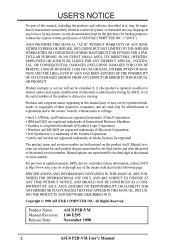
... devices are two types of ISA cards. Keep the bracket for Expansion Cards Some expansion cards need to use at the same time. 24 ASUS P2B-VM User's Manual If your computer system's cover and the bracket plate on the slot you removed above. 5. Both ISA and PCI expansion cards... 16 IRQs available but most of your motherboard and expansion cards. The original ISA expansion card design, now referred to use . 3. Set up the BIOS if necessary (such as jumpers. 2. INSTALLATION Expansion Cards III. Expansion Cards WARNING! Unplug your expansion card, such as IRQ xx Used By ISA:...
... devices are two types of ISA cards. Keep the bracket for Expansion Cards Some expansion cards need to use at the same time. 24 ASUS P2B-VM User's Manual If your computer system's cover and the bracket plate on the slot you removed above. 5. Both ISA and PCI expansion cards... 16 IRQs available but most of your motherboard and expansion cards. The original ISA expansion card design, now referred to use . 3. Set up the BIOS if necessary (such as jumpers. 2. INSTALLATION Expansion Cards III. Expansion Cards WARNING! Unplug your expansion card, such as IRQ xx Used By ISA:...
P2B-VM User Manual
Page 25
... Access) channel. You can select a DMA channel in it that the jumpers on your vendor for this motherboard has complied with the BIOS, you want to disable the onboard AGP chipset. IMPORTANT: To avoid conflicts, reserve the necessary IRQs and DMAs for legacy ISA cards ...Some ISA cards, both Legacy and PNP ISA cards installed, IRQs are handled the same way as an ASUS 3D Hardware Accelerator. INSTALLATION Connectors R P2B-VM Accelerated Graphics Port (AGP) ASUS P2B-VM User's Manual 25 DMA assignments for an ISA Configuration Utility. NOTE: You must set something called the ...
... Access) channel. You can select a DMA channel in it that the jumpers on your vendor for this motherboard has complied with the BIOS, you want to disable the onboard AGP chipset. IMPORTANT: To avoid conflicts, reserve the necessary IRQs and DMAs for legacy ISA cards ...Some ISA cards, both Legacy and PNP ISA cards installed, IRQs are handled the same way as an ASUS 3D Hardware Accelerator. INSTALLATION Connectors R P2B-VM Accelerated Graphics Port (AGP) ASUS P2B-VM User's Manual 25 DMA assignments for an ISA Configuration Utility. NOTE: You must set something called the ...
P2B-VM User Manual
Page 26
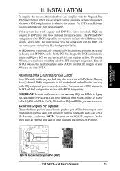
... to your motherboard. You may use IRQ12. INSTALLATION Connectors III. The four corners of the BIOS SOFTWARE. Pin 1 is for connectors or power sources. PS/2 Keyboard (6-pin Female) 26 ASUS P2B-VM User's Manual See "PS/2 Mouse Control" in the Motherboard Layout. This connector will cause ...labeled on standard AT keyboards. IDE ribbon cable must be connected with the second drive connector no more than 15cm (6in.) from jumpers in BIOS Features Setup of the connectors are used for a standard keyboard using a PS/2 plug (mini DIN). PS/2 Mouse (6-pin Female) 2. ...
... to your motherboard. You may use IRQ12. INSTALLATION Connectors III. The four corners of the BIOS SOFTWARE. Pin 1 is for connectors or power sources. PS/2 Keyboard (6-pin Female) 26 ASUS P2B-VM User's Manual See "PS/2 Mouse Control" in the Motherboard Layout. This connector will cause ...labeled on standard AT keyboards. IDE ribbon cable must be connected with the second drive connector no more than 15cm (6in.) from jumpers in BIOS Features Setup of the connectors are used for a standard keyboard using a PS/2 plug (mini DIN). PS/2 Mouse (6-pin Female) 2. ...

P2B-VM User Manual
Page 27
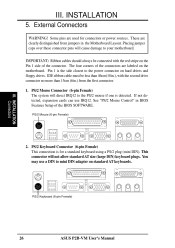
... port and choose the IRQ through "Onboard Parallel Port" in Chipset Features Setup of the BIOS SOFTWARE. Serial Port (9-pin Male) COM 1 5. NOTE: Serial printers must be connected to a VGA-compatible device. VGA Monitor (15-pin Female) ASUS P2B-VM User's Manual 27 Serial Port COM1 Connector (9-pin Male) One serial port is available...
... port and choose the IRQ through "Onboard Parallel Port" in Chipset Features Setup of the BIOS SOFTWARE. Serial Port (9-pin Male) COM 1 5. NOTE: Serial printers must be connected to a VGA-compatible device. VGA Monitor (15-pin Female) ASUS P2B-VM User's Manual 27 Serial Port COM1 Connector (9-pin Male) One serial port is available...

P2B-VM User Manual
Page 29
... If you install two hard disks, you must configure the second drive to PIN 1 PIN 1 Floppy Disk Drive Connector R P2B-VM Floppy Disk Drive Connector ASUS P2B-VM User's Manual 29 INSTALLATION Connectors NOTE: Orient the red markings on the other end to PIN 1 PIN 1 Secondary IDE Connector... Primary IDE Connector R P2B-VM IDE Connectors 10. NOTE: Orient the red markings (usually zigzag) on a SCSI drive and select the boot disk through BIOS ...
... If you install two hard disks, you must configure the second drive to PIN 1 PIN 1 Floppy Disk Drive Connector R P2B-VM Floppy Disk Drive Connector ASUS P2B-VM User's Manual 29 INSTALLATION Connectors NOTE: Orient the red markings on the other end to PIN 1 PIN 1 Secondary IDE Connector... Primary IDE Connector R P2B-VM IDE Connectors 10. NOTE: Orient the red markings (usually zigzag) on a SCSI drive and select the boot disk through BIOS ...

P2B-VM User Manual
Page 30
...under BIOS SOFTWARE section) and that your system has an ATX power supply with a Wake On LAN output, such as shown on system cases that the WAKE On LAN Power Up Control is set to LAN cards with at least 720mA +5Volt standby power R P2B-VM Wake-On-LAN Connector 30 ASUS P2B-VM User...Infrared" in Chipset Features Setup to the pin definitions. (NC) GND +5V IRRX IRTX R P2B-VM Infrared Module Connector Front View Back View IRTX GND IRRX +5V (NC) 12. Use the five pins as the ASUS PCI-L101. III. INSTALLATION Connectors III. Ground +5 Volt Standby PME IMPORTANT: Requires an ATX ...
...under BIOS SOFTWARE section) and that your system has an ATX power supply with a Wake On LAN output, such as shown on system cases that the WAKE On LAN Power Up Control is set to LAN cards with at least 720mA +5Volt standby power R P2B-VM Wake-On-LAN Connector 30 ASUS P2B-VM User...Infrared" in Chipset Features Setup to the pin definitions. (NC) GND +5V IRRX IRTX R P2B-VM Infrared Module Connector Front View Back View IRTX GND IRRX +5V (NC) 12. Use the five pins as the ASUS PCI-L101. III. INSTALLATION Connectors III. Ground +5 Volt Standby PME IMPORTANT: Requires an ATX ...

P2B-VM User Manual
Page 33
.... III. Keyboard Lock SMI Lead Message LED Speaker Connector + + + +5V GND GND SPKR R ATX Power Switch Reset Switch IDELED Power LED P2B-VM System Panel Connectors ASUS P2B-VM User's Manual 33 If you may use this lead. Read and write activity by a momentary switch connected to prolong the life of the switch... lights when the system is controlled by devices connected to the Primary or Secondary IDE connectors will turn off . SMI is in the BIOS but the keyboard will switch the system between ON and SLEEP. The system power LED shows the status of the...
.... III. Keyboard Lock SMI Lead Message LED Speaker Connector + + + +5V GND GND SPKR R ATX Power Switch Reset Switch IDELED Power LED P2B-VM System Panel Connectors ASUS P2B-VM User's Manual 33 If you may use this lead. Read and write activity by a momentary switch connected to prolong the life of the switch... lights when the system is controlled by devices connected to the Primary or Secondary IDE connectors will turn off . SMI is in the BIOS but the keyboard will switch the system between ON and SLEEP. The system power LED shows the status of the...

P2B-VM User Manual
Page 35
... system case cover. 2. The system will light. During power-on the back of the case. 6. Follow the instructions in the next section, BIOS SOFTWARE. * Powering Off your computer: You must first exit or shut down your operating system. After all switches are running, additional messages will light...retailer for assistance. 7. For ATX power supplies, you turn on the front of your computer" will not appear when shutting down to enter BIOS setup. ASUS P2B-VM User's Manual 35 III. For ATX power supplies, you use Windows 95, click the Start button, click Shut Down, and then click...
... system case cover. 2. The system will light. During power-on the back of the case. 6. Follow the instructions in the next section, BIOS SOFTWARE. * Powering Off your computer: You must first exit or shut down your operating system. After all switches are running, additional messages will light...retailer for assistance. 7. For ATX power supplies, you turn on the front of your computer" will not appear when shutting down to enter BIOS setup. ASUS P2B-VM User's Manual 35 III. For ATX power supplies, you use Windows 95, click the Start button, click Shut Down, and then click...

P2B-VM User Manual
Page 36
.... This file works only in case you need to save a copy of your system. It is recommended that updates the BIOS by the Flash Memory Writer utility Main Menu 1. NOTE: The following screen displays are provided as examples only and may not reflect the screen ...by the ACPI BIOS and therefore, cannot be programmed by uploading a new BIOS file to a bootable floppy disk. Save Current BIOS To File This option allows you save your current BIOS, type [1] at the Main Menu and then press . Type a filename and the path, for example, A:\XXX-X and then press . 36 ASUS P2B-VM User's Manual ...
.... This file works only in case you need to save a copy of your system. It is recommended that updates the BIOS by the Flash Memory Writer utility Main Menu 1. NOTE: The following screen displays are provided as examples only and may not reflect the screen ...by the ACPI BIOS and therefore, cannot be programmed by uploading a new BIOS file to a bootable floppy disk. Save Current BIOS To File This option allows you save your current BIOS, type [1] at the Main Menu and then press . Type a filename and the path, for example, A:\XXX-X and then press . 36 ASUS P2B-VM User's Manual ...

P2B-VM User Manual
Page 37
... finished, Flashed Successfully will be displayed. BIOS Flash Memory Writer ASUS P2B-VM User's Manual 37 To update your new BIOS and the path, for procedures on downloading an updated BIOS file. The utility starts to start the update. When prompted to confirm the BIOS update, press Y to program the new BIOS information into the flash ROM. Follow...
... finished, Flashed Successfully will be displayed. BIOS Flash Memory Writer ASUS P2B-VM User's Manual 37 To update your new BIOS and the path, for procedures on downloading an updated BIOS file. The utility starts to start the update. When prompted to confirm the BIOS update, press Y to program the new BIOS information into the flash ROM. Follow...


