P2B-S User Manual
Page 9
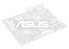
...hardware to communicate within a standard protocol creating a higher level of compatibility. (Requires DMI-enabled components.) II. II. FEATURES Motherboard Parts ASUS P2B-L/P2B-S/P2B-LS Motherboard SEC CPU Slot T: PS/2 Mouse B: PS/2 Keyboard T: USB Port 1 B: USB Port 2 COM 1 (Bottom) Parallel (Top) Serial (Bottom) COM 2 (Bottom) Intel 440BX AGPset Fast-SCSI Connector 4 DIMM ...-Fast/ Wide SCSI Chipset (optional) Accelerated Graphics Port 4PCI Slots Multi-I/O Hardware Monitor 2 ISA Slots Intel PIIX4E Programmable PCIset 2Mbit Flash ROM ASUS P2B-L/P2B-S/P2B-LS User's Manual 9
...hardware to communicate within a standard protocol creating a higher level of compatibility. (Requires DMI-enabled components.) II. II. FEATURES Motherboard Parts ASUS P2B-L/P2B-S/P2B-LS Motherboard SEC CPU Slot T: PS/2 Mouse B: PS/2 Keyboard T: USB Port 1 B: USB Port 2 COM 1 (Bottom) Parallel (Top) Serial (Bottom) COM 2 (Bottom) Intel 440BX AGPset Fast-SCSI Connector 4 DIMM ...-Fast/ Wide SCSI Chipset (optional) Accelerated Graphics Port 4PCI Slots Multi-I/O Hardware Monitor 2 ISA Slots Intel PIIX4E Programmable PCIset 2Mbit Flash ROM ASUS P2B-L/P2B-S/P2B-LS User's Manual 9

P2B-S User Manual
Page 10
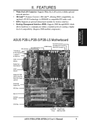
INSTALLATION ASUS P2B-L/P2B-S/P2B-LS Motherboard Layout DIMM Socket 0 (64/72 bit, 168 pin module) DIMM Socket 1 (64/72 bit, 168 pin module) DIMM Socket 2 (64/72 bit, 168 ... Contact CPU Slot PS/2 Power Supply Fan Mouse (top port) Keyboard (bottom port) USB 1 (top port) USB 2 (bottom port) USB KBPWR COM 1 TRCPU CPU_FAN Intel 440BX AGPset FS2 FS1 BUS Freq. III. INSTALLATION Board Layout 10 ASUS P2B-L/P2B-S/P2B-LS User's Manual Ratio ASUS A97127F Chipset BF3 BF2 BF1 BF0 BIOS Power (CR2032 3V Lithium Cell) SCSILED...
INSTALLATION ASUS P2B-L/P2B-S/P2B-LS Motherboard Layout DIMM Socket 0 (64/72 bit, 168 pin module) DIMM Socket 1 (64/72 bit, 168 pin module) DIMM Socket 2 (64/72 bit, 168 ... Contact CPU Slot PS/2 Power Supply Fan Mouse (top port) Keyboard (bottom port) USB 1 (top port) USB 2 (bottom port) USB KBPWR COM 1 TRCPU CPU_FAN Intel 440BX AGPset FS2 FS1 BUS Freq. III. INSTALLATION Board Layout 10 ASUS P2B-L/P2B-S/P2B-LS User's Manual Ratio ASUS A97127F Chipset BF3 BF2 BF1 BF0 BIOS Power (CR2032 3V Lithium Cell) SCSILED...
P2B-S User Manual
Page 11
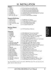
... p. 26 PS/2 Keyboard Connector (6-pin female) p. 26 PS/2 Mouse Connector (6-pin female) 3) PRINTER p. 27 Parallel (Printer) Port Connector (25-pin female) 4) COM1/COM2 5) RJ-45 6) USB p. 27 Serial Port COM1/COM2 (two 9-pin male) p. 27 RJ-45 Connector (8-pin female) p. 28 Universal Serial BUS Ports 1 & 2 (two 4 pin female) 7) A p. 28 LAN Condition... Connector (20 pins) *The onboard hardware monitor uses the address 290H-297H so legacy ISA cards must not use this address, otherwise conflicts will occur. ASUS P2B-L/P2B-S/P2B-LS User's Manual 11
... p. 26 PS/2 Keyboard Connector (6-pin female) p. 26 PS/2 Mouse Connector (6-pin female) 3) PRINTER p. 27 Parallel (Printer) Port Connector (25-pin female) 4) COM1/COM2 5) RJ-45 6) USB p. 27 Serial Port COM1/COM2 (two 9-pin male) p. 27 RJ-45 Connector (8-pin female) p. 28 Universal Serial BUS Ports 1 & 2 (two 4 pin female) 7) A p. 28 LAN Condition... Connector (20 pins) *The onboard hardware monitor uses the address 290H-297H so legacy ISA cards must not use this address, otherwise conflicts will occur. ASUS P2B-L/P2B-S/P2B-LS User's Manual 11

P2B-S User Manual
Page 28
Universal Serial BUS Ports 1 & 2 (Two 4-pin Female) Two USB ports are available for connecting USB devices. Link LED Connector Activity LED Connector Speed LED Connector R R III. After connecting the single end to the board... red stripe to system cases that support this feature. INSTALLATION Connectors P2B-L/S/LS Network Condition LED Connectors 8. USB 1 USB 2 P2B-L/S/LS Universal Serial Bus (USB) 7. This module mounts to Pin 1 Floppy Drive Connector Pin 1 P2B-L/S/LS Floppy Disk Drive Connector 28 ASUS P2B-L/P2B-S/P2B-LS User's Manual III. LAN Condition Connector (6-pin A) (optional...
Universal Serial BUS Ports 1 & 2 (Two 4-pin Female) Two USB ports are available for connecting USB devices. Link LED Connector Activity LED Connector Speed LED Connector R R III. After connecting the single end to the board... red stripe to system cases that support this feature. INSTALLATION Connectors P2B-L/S/LS Network Condition LED Connectors 8. USB 1 USB 2 P2B-L/S/LS Universal Serial Bus (USB) 7. This module mounts to Pin 1 Floppy Drive Connector Pin 1 P2B-L/S/LS Floppy Disk Drive Connector 28 ASUS P2B-L/P2B-S/P2B-LS User's Manual III. LAN Condition Connector (6-pin A) (optional...

P2B-S User Manual
Page 53
... an ICU to its address range, select a base address from functioning. If you can be extended up tp 25m. IV. BIOS Plug & Play / PCI ASUS P2B-L/P2B-S/P2B-LS User's Manual 53 The first option, the default setting, indicates either 8K, 16K, 36K, or 64K. the ISA MEM Block SIZE field will then... either that the displayed DMA channel is not used or an ICU is being used to enable or disable the onboard termination for expansion cards. USB IRQ (Enabled) Enabled reserves an IRQ# for single-ended (SE) devices, such as disk drives, using any memory segment within the C800H and DFFFH...
... an ICU to its address range, select a base address from functioning. If you can be extended up tp 25m. IV. BIOS Plug & Play / PCI ASUS P2B-L/P2B-S/P2B-LS User's Manual 53 The first option, the default setting, indicates either 8K, 16K, 36K, or 64K. the ISA MEM Block SIZE field will then... either that the displayed DMA channel is not used or an ICU is being used to enable or disable the onboard termination for expansion cards. USB IRQ (Enabled) Enabled reserves an IRQ# for single-ended (SE) devices, such as disk drives, using any memory segment within the C800H and DFFFH...


