
P2B-S User Manual
Page 2
...writing by the digit before and after the period of the manual revision number. Product Name: ASUS P2B-L/P2B-S/P2B-LS Manual Revision: 1.06 E265 Release Date: August 1998 2 ASUS P2B-L/P2B-S/P2B-LS User's Manual Manual updates are represented by the purchaser for identification or explanation and to infringe...of International Business Machines. • Symbios is defaced or missing. For previous or updated manuals, BIOS, drivers, or product release information, contact ASUS at http://www.asus.com.tw or through any means, except documentation kept by the third digit in the manual ...
...writing by the digit before and after the period of the manual revision number. Product Name: ASUS P2B-L/P2B-S/P2B-LS Manual Revision: 1.06 E265 Release Date: August 1998 2 ASUS P2B-L/P2B-S/P2B-LS User's Manual Manual updates are represented by the purchaser for identification or explanation and to infringe...of International Business Machines. • Symbios is defaced or missing. For previous or updated manuals, BIOS, drivers, or product release information, contact ASUS at http://www.asus.com.tw or through any means, except documentation kept by the third digit in the manual ...
P2B-S User Manual
Page 4
...of Standard CMOS Setup 40 BIOS Features Setup 43 Details of BIOS Features Setup 43 Chipset Features Setup 46 Details of Chipset Features Setup 46 Power Management Setup 49 Details of Power Management Setup 49 4 ASUS P2B-L/P2B-S/P2B-LS User's Manual Expansion ... Cards 25 ISA Cards and Hardware Monitor 25 Accelerated Graphics Port 25 5. CONTENTS I. INSTALLATION ASUS P2B-L/P2B-S/P2B-LS Motherboard Layout 10 Installation Steps 12 1. FEATURES Features 8 ASUS P2B-L/P2B-S/P2B-LS Motherboard 9 III. Central Processing Unit (CPU 19 Pentium II Processor 19 AAVID Heatsink 23...
...of Standard CMOS Setup 40 BIOS Features Setup 43 Details of BIOS Features Setup 43 Chipset Features Setup 46 Details of Chipset Features Setup 46 Power Management Setup 49 Details of Power Management Setup 49 4 ASUS P2B-L/P2B-S/P2B-LS User's Manual Expansion ... Cards 25 ISA Cards and Hardware Monitor 25 Accelerated Graphics Port 25 5. CONTENTS I. INSTALLATION ASUS P2B-L/P2B-S/P2B-LS Motherboard Layout 10 Installation Steps 12 1. FEATURES Features 8 ASUS P2B-L/P2B-S/P2B-LS Motherboard 9 III. Central Processing Unit (CPU 19 Pentium II Processor 19 AAVID Heatsink 23...

P2B-S User Manual
Page 5
CONTENTS PNP and PCI Setup 52 Details of PNP and PCI Setup 52 Load BIOS Defaults 54 Load Setup Defaults 54 Supervisor Password and User Password 55 IDE HDD Auto Detection 56 Save & Exit Setup 57 Exit Without Saving 57 V. ... 64 DOS and Windows 3.1 Setup for DOS/Windows 3.1x Users 83 DOS Formatting Utilities 84 Low-level Formatter (scsifmt 84 Formatter and Partitioner (afdisk 85 ASUS P2B-L/P2B-S/P2B-LS User's Manual 5 ADAPTEC EZ-SCSI UTILITY Quick Start Instructions 79 Troubleshooting Tips 80 Information for Novell 65 Windows NT Server or Workstation 66 Windows...
CONTENTS PNP and PCI Setup 52 Details of PNP and PCI Setup 52 Load BIOS Defaults 54 Load Setup Defaults 54 Supervisor Password and User Password 55 IDE HDD Auto Detection 56 Save & Exit Setup 57 Exit Without Saving 57 V. ... 64 DOS and Windows 3.1 Setup for DOS/Windows 3.1x Users 83 DOS Formatting Utilities 84 Low-level Formatter (scsifmt 84 Formatter and Partitioner (afdisk 85 ASUS P2B-L/P2B-S/P2B-LS User's Manual 5 ADAPTEC EZ-SCSI UTILITY Quick Start Instructions 79 Troubleshooting Tips 80 Information for Novell 65 Windows NT Server or Workstation 66 Windows...
P2B-S User Manual
Page 7
...pin Fast & Wide SCSI cable (optional) 50-pin Fast SCSI cable (optional) Network condition connector module (optional) ASUS P2B-L/P2B-S/P2B-LS User's Manual 7 INTRODUCTION How this Manual is Organized This manual is complete. Support Software VI. Adaptec SCSI ... is divided into the following sections: I . I . BIOS Software V. DMI Utility VII. INTRODUCTION Manual / Checklist I. Features III. Instructions on setting up the BIOS software ASUS Smart Motherboard Support CD BIOS supported Desktop Management Interface Information on setting up the motherboard. Installation...
...pin Fast & Wide SCSI cable (optional) 50-pin Fast SCSI cable (optional) Network condition connector module (optional) ASUS P2B-L/P2B-S/P2B-LS User's Manual 7 INTRODUCTION How this Manual is Organized This manual is complete. Support Software VI. Adaptec SCSI ... is divided into the following sections: I . I . BIOS Software V. DMI Utility VII. INTRODUCTION Manual / Checklist I. Features III. Instructions on setting up the BIOS software ASUS Smart Motherboard Support CD BIOS supported Desktop Management Interface Information on setting up the motherboard. Installation...
P2B-S User Manual
Page 8
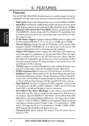
FEATURES Specifications II. FEATURES Features The ASUS P2B-L/P2B-S/P2B-LS motherboards are also supported without affecting system performance by taking advantage of the benefits of low-voltage differential (LVD) technology. • AGP Slot: Supports ... DMA/33 Bus Master IDE/Floppy: Comes with an onboard PCI Bus Master IDE controller with EPP and ECP capabilities. BIOS supports IDE CD-ROM or SCSI device boot-up to CPU. 8 ASUS P2B-L/P2B-S/P2B-LS User's Manual Supports Japanese standard "Floppy 3 mode" (3.5-inch disk drive: 1.2MB) and LS-120 floppy disk drives (3.5-inch...
FEATURES Specifications II. FEATURES Features The ASUS P2B-L/P2B-S/P2B-LS motherboards are also supported without affecting system performance by taking advantage of the benefits of low-voltage differential (LVD) technology. • AGP Slot: Supports ... DMA/33 Bus Master IDE/Floppy: Comes with an onboard PCI Bus Master IDE controller with EPP and ECP capabilities. BIOS supports IDE CD-ROM or SCSI device boot-up to CPU. 8 ASUS P2B-L/P2B-S/P2B-LS User's Manual Supports Japanese standard "Floppy 3 mode" (3.5-inch disk drive: 1.2MB) and LS-120 floppy disk drives (3.5-inch...
P2B-S User Manual
Page 9
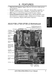
.../ Wide SCSI Chipset (optional) Accelerated Graphics Port 4PCI Slots Multi-I/O Hardware Monitor 2 ISA Slots Intel PIIX4E Programmable PCIset 2Mbit Flash ROM ASUS P2B-L/P2B-S/P2B-LS User's Manual 9 FEATURES • Wake-On-LAN Connector: Supports Wake-On-LAN activity with the optional network interface. •... an optional infrared port module for wireless interface. • Desktop Management Interface (DMI): Supports DMI through BIOS, which allows hardware to communicate within a standard protocol creating a higher level of compatibility. (Requires DMI-enabled components.) II.
.../ Wide SCSI Chipset (optional) Accelerated Graphics Port 4PCI Slots Multi-I/O Hardware Monitor 2 ISA Slots Intel PIIX4E Programmable PCIset 2Mbit Flash ROM ASUS P2B-L/P2B-S/P2B-LS User's Manual 9 FEATURES • Wake-On-LAN Connector: Supports Wake-On-LAN activity with the optional network interface. •... an optional infrared port module for wireless interface. • Desktop Management Interface (DMI): Supports DMI through BIOS, which allows hardware to communicate within a standard protocol creating a higher level of compatibility. (Requires DMI-enabled components.) II.

P2B-S User Manual
Page 10
... (CR2032 3V Lithium Cell) SCSILED CHASSIS WOL_CON EXTBATT 2Mbit Flash EEPROM (Programmable BIOS) CHA_FAN PANEL IDELED Combine IR Speaker NOTE: Greyed components are optional at the time of purchase. III. INSTALLATION ASUS P2B-L/P2B-S/P2B-LS Motherboard Layout DIMM Socket 0 (64/72 bit, 168 pin module) DIMM...1 (top port) USB 2 (bottom port) USB KBPWR COM 1 TRCPU CPU_FAN Intel 440BX AGPset FS2 FS1 BUS Freq. INSTALLATION Board Layout 10 ASUS P2B-L/P2B-S/P2B-LS User's Manual III. FS0 68 34 34 68 COM 2 RJ-45 FLOPPY LAN Activity LED Connector 35 1 35 1 50-Pin SCSI...
... (CR2032 3V Lithium Cell) SCSILED CHASSIS WOL_CON EXTBATT 2Mbit Flash EEPROM (Programmable BIOS) CHA_FAN PANEL IDELED Combine IR Speaker NOTE: Greyed components are optional at the time of purchase. III. INSTALLATION ASUS P2B-L/P2B-S/P2B-LS Motherboard Layout DIMM Socket 0 (64/72 bit, 168 pin module) DIMM...1 (top port) USB 2 (bottom port) USB KBPWR COM 1 TRCPU CPU_FAN Intel 440BX AGPset FS2 FS1 BUS Freq. INSTALLATION Board Layout 10 ASUS P2B-L/P2B-S/P2B-LS User's Manual III. FS0 68 34 34 68 COM 2 RJ-45 FLOPPY LAN Activity LED Connector 35 1 35 1 50-Pin SCSI...
P2B-S User Manual
Page 12
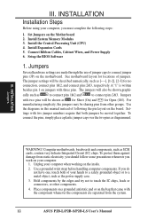
... Jumpers WARNING! To protect them against damage from other components. 4. Connect Ribbon Cables, Cabinet Wires, and Power Supply 6. Setup the BIOS Software 1. A "1" is written besides pin 1 on the motherboard. To connect the pins, simply place a plastic jumper cap over the... pins will be shown graphi- Install the Central Processing Unit (CPU) 4. Jumpers Several hardware settings are separated from the system. 12 ASUS P2B-L/P2B-S/P2B-LS User's Manual The jumpers will be described numerically, such as [----], [1-2], [2-3] for locations of jumper caps to a metal object...
... Jumpers WARNING! To protect them against damage from other components. 4. Connect Ribbon Cables, Cabinet Wires, and Power Supply 6. Setup the BIOS Software 1. A "1" is written besides pin 1 on the motherboard. To connect the pins, simply place a plastic jumper cap over the... pins will be shown graphi- Install the Central Processing Unit (CPU) 4. Jumpers Several hardware settings are separated from the system. 12 ASUS P2B-L/P2B-S/P2B-LS User's Manual The jumpers will be described numerically, such as [----], [1-2], [2-3] for locations of jumper caps to a metal object...

P2B-S User Manual
Page 13
... points to Disable because not all computers have the right ATX power supply. KBPWR 123 Disable (Default) KBPWR 123 Enable R P2B-L/S/LS Keyboard Power (Wake) Up ASUS P2B-L/P2B-S/P2B-LS User's Manual 13 INSTALLATION Jumper Settings 1. Keyboard Power Up (KBPWR) This allows you to Enable and if you do ... power, (2) Short the two solder points labeled CLRTC, (3) Turn on the +5VSB lead and the new ACPI BIOS support. Set to Enable if you set to clear CMOS R CLRTC P2B-L/S/LS Real Time Clock RAM (CLRTC) 2. The default is powered by pressing ) to re-enter user preferences. ...
... points to Disable because not all computers have the right ATX power supply. KBPWR 123 Disable (Default) KBPWR 123 Enable R P2B-L/S/LS Keyboard Power (Wake) Up ASUS P2B-L/P2B-S/P2B-LS User's Manual 13 INSTALLATION Jumper Settings 1. Keyboard Power Up (KBPWR) This allows you to Enable and if you do ... power, (2) Short the two solder points labeled CLRTC, (3) Turn on the +5VSB lead and the new ACPI BIOS support. Set to Enable if you set to clear CMOS R CLRTC P2B-L/S/LS Real Time Clock RAM (CLRTC) 2. The default is powered by pressing ) to re-enter user preferences. ...

P2B-S User Manual
Page 17
...8, 16, 32, 64, 128, 256MB x1 Socket 4 (Rows 6&7) SDRAM 8, 16, 32, 64, 128, 256MB x1 Total System Memory (Max 1024MB) = ASUS Memory Module Example: III. ASUS P2B-L/P2B-S/P2B-LS User's Manual 17 Install memory in IV. One side (with memory chips) of the strict timing issues involved under "Chipset Features Setup... ECC. • SDRAM chips are generally thinner with higher pin density than traditional EDO (Extended Data Output) chips. • BIOS shows SDRAM memory on the motherboard. III. System Memory (DIMM) This motherboard uses only Dual Inline Memory Modules (DIMMs).
...8, 16, 32, 64, 128, 256MB x1 Socket 4 (Rows 6&7) SDRAM 8, 16, 32, 64, 128, 256MB x1 Total System Memory (Max 1024MB) = ASUS Memory Module Example: III. ASUS P2B-L/P2B-S/P2B-LS User's Manual 17 Install memory in IV. One side (with memory chips) of the strict timing issues involved under "Chipset Features Setup... ECC. • SDRAM chips are generally thinner with higher pin density than traditional EDO (Extended Data Output) chips. • BIOS shows SDRAM memory on the motherboard. III. System Memory (DIMM) This motherboard uses only Dual Inline Memory Modules (DIMMs).

P2B-S User Manual
Page 24
...removed above. 5. INSTALLATION Expansion Cards III. Expansion Cards WARNING! Keep the bracket for possible future use an IRQ to PCI cards. Set up the BIOS if necessary (such as jumpers. 2. Install the necessary software drivers for expansion cards. If your expansion card, such as IRQ xx Used By ISA:... bus. You may cause severe damage to see a map of ISA cards. Failure to do so may use at the same time. 24 ASUS P2B-L/P2B-S/P2B-LS User's Manual Unplug your expansion card. System IRQs are available to cards installed in the ISA expansion bus first, then any remaining IRQs ...
...removed above. 5. INSTALLATION Expansion Cards III. Expansion Cards WARNING! Keep the bracket for possible future use an IRQ to PCI cards. Set up the BIOS if necessary (such as jumpers. 2. Install the necessary software drivers for expansion cards. If your expansion card, such as IRQ xx Used By ISA:... bus. You may cause severe damage to see a map of ISA cards. Failure to do so may use at the same time. 24 ASUS P2B-L/P2B-S/P2B-LS User's Manual Unplug your expansion card. System IRQs are available to cards installed in the ISA expansion bus first, then any remaining IRQs ...

P2B-S User Manual
Page 25
... has both legacy and PnP, may contact your PCI cards to reserve). In the PCI bus design, the BIOS automatically assigns an IRQ to set the jumpers on this address or else conflicts will occur. To install a ... a DMA (Direct Memory Access) channel. For PnP cards, IRQs are assigned to support a new generation of the BIOS setup utility can select a DMA channel in IRQ xx Used By ISA and DMA x Used By ISA for ISA ...by legacy cards. Assigning DMA Channels for those not used by legacy cards. R P2B-L/S/LS Accelerated Graphics Port (AGP) ASUS P2B-L/P2B-S/P2B-LS User's Manual 25
... has both legacy and PnP, may contact your PCI cards to reserve). In the PCI bus design, the BIOS automatically assigns an IRQ to set the jumpers on this address or else conflicts will occur. To install a ... a DMA (Direct Memory Access) channel. For PnP cards, IRQs are assigned to support a new generation of the BIOS setup utility can select a DMA channel in IRQ xx Used By ISA and DMA x Used By ISA for ISA ...by legacy cards. Assigning DMA Channels for those not used by legacy cards. R P2B-L/S/LS Accelerated Graphics Port (AGP) ASUS P2B-L/P2B-S/P2B-LS User's Manual 25

P2B-S User Manual
Page 26
...BIOS Features Setup of the connectors are used for a standard keyboard using a PS/2 plug (mini DIN). IDE ribbon cable must be connected with the second drive connector no more than 46cm(18in), with the red stripe on the motherboard. P2B-L/S/LS PS/2 Mouse (6-pin Female) 26 ASUS P2B-L/P2B-S/P2B...-LS User's Manual P2B-L/S/LS PS/2 Keyboard (6-pin Female) 2. INSTALLATION Connectors III. III. Placing jumper caps over ...
...BIOS Features Setup of the connectors are used for a standard keyboard using a PS/2 plug (mini DIN). IDE ribbon cable must be connected with the second drive connector no more than 46cm(18in), with the red stripe on the motherboard. P2B-L/S/LS PS/2 Mouse (6-pin Female) 26 ASUS P2B-L/P2B-S/P2B...-LS User's Manual P2B-L/S/LS PS/2 Keyboard (6-pin Female) 2. INSTALLATION Connectors III. III. Placing jumper caps over ...

P2B-S User Manual
Page 27
... and choose the IRQ through "Onboard Parallel Port" in Chipset Features Setup of the BIOS SOFTWARE. NOTE: Serial printers must be connected to a host or a hub. See "Onboard Serial Port..." P2B-L/S/LS RJ-45 Port ASUS P2B-L/P2B-S/P2B-LS User's Manual 27 P2B-L/S/LS Parallel Port (25-pin Female) III. INSTALLATION 3. Parallel Printer Connector (25-pin...
... and choose the IRQ through "Onboard Parallel Port" in Chipset Features Setup of the BIOS SOFTWARE. NOTE: Serial printers must be connected to a host or a hub. See "Onboard Serial Port..." P2B-L/S/LS RJ-45 Port ASUS P2B-L/P2B-S/P2B-LS User's Manual 27 P2B-L/S/LS Parallel Port (25-pin Female) III. INSTALLATION 3. Parallel Printer Connector (25-pin...

P2B-S User Manual
Page 29
... Primary IDE Connector Secondary IDE Connector III. TIP: If the case-mounted LED does not light, try reversing the 2-pin plug. INSTALLATION 9. BIOS now supports SCSI device or IDE CD-ROM bootup (see "HDD Sequence SCSI/IDE First" & "Boot Sequence" in the wrong orientation when ...connected to the Primary or Secondary IDE connectors will cause the IDELED to blink. IDELED SCSILED P2B-L/S/LS IDE/SCSI Device Activity LED R ASUS P2B-L/P2B-S/P2B-LS User's Manual 29 INSTALLATION Connectors R P2B-L/S/LS IDE Connectors 10. If you install two hard disks, you must configure the second ...
... Primary IDE Connector Secondary IDE Connector III. TIP: If the case-mounted LED does not light, try reversing the 2-pin plug. INSTALLATION 9. BIOS now supports SCSI device or IDE CD-ROM bootup (see "HDD Sequence SCSI/IDE First" & "Boot Sequence" in the wrong orientation when ...connected to the Primary or Secondary IDE connectors will cause the IDELED to blink. IDELED SCSILED P2B-L/S/LS IDE/SCSI Device Activity LED R ASUS P2B-L/P2B-S/P2B-LS User's Manual 29 INSTALLATION Connectors R P2B-L/S/LS IDE Connectors 10. If you install two hard disks, you must configure the second ...

P2B-S User Manual
Page 35
...power off the power switch. You may then turn on your devices in the next section, BIOS SOFTWARE. * Powering Off your computer: You must first exit or shut down to enter BIOS setup. For ATX power supplies, you can now safely turn on the power, the system may... 95, click the Start button, click Shut Down, and then click Shut down with a surge protector. 5. Follow the instructions in the following order: a. ASUS P2B-L/P2B-S/P2B-LS User's Manual 35 Be sure that is pressed. External SCSI devices (starting with ). 3. While the tests are off your system user's manual. 4....
...power off the power switch. You may then turn on your devices in the next section, BIOS SOFTWARE. * Powering Off your computer: You must first exit or shut down to enter BIOS setup. For ATX power supplies, you can now safely turn on the power, the system may... 95, click the Start button, click Shut Down, and then click Shut down with a surge protector. 5. Follow the instructions in the following order: a. ASUS P2B-L/P2B-S/P2B-LS User's Manual 35 Be sure that is pressed. External SCSI devices (starting with ). 3. While the tests are off your system user's manual. 4....

P2B-S User Manual
Page 36
...case you to the programmable flash ROM chip on your current BIOS, type [1] at the Main Menu and then press . Main Menu 1. Type a filename and the path, for example, A:\XXXXX-X and then press . 36 ASUS P2B-L/P2B-S/P2B-LS User's Manual If "unknown" is displayed after Flash Memory...:, the memory chip is either not programmable or is recommended that updates the BIOS by the Flash Memory Writer utility. To determine the BIOS version of your screen during bootup. IV...
...case you to the programmable flash ROM chip on your current BIOS, type [1] at the Main Menu and then press . Main Menu 1. Type a filename and the path, for example, A:\XXXXX-X and then press . 36 ASUS P2B-L/P2B-S/P2B-LS User's Manual If "unknown" is displayed after Flash Memory...:, the memory chip is either not programmable or is recommended that updates the BIOS by the Flash Memory Writer utility. To determine the BIOS version of your screen during bootup. IV...

P2B-S User Manual
Page 37
... instructions to start the update. BIOS SOFTWARE 2. Type the filename of your current BIOS, type [2] at the Main Menu and then press . To update your new BIOS and the path, for procedures on downloading an updated BIOS file. Update BIOS Including Boot Block and ESCD This... block from a new BIOS file. The utility starts to program the new BIOS information into the flash ROM. The Update BIOS Including Boot Block and ESCD screen appears. When the programming is finished, Flashed Successfully will be displayed. BIOS Flash Memory Writer ASUS P2B-L/P2B-S/P2B-LS User's Manual 37...
... instructions to start the update. BIOS SOFTWARE 2. Type the filename of your current BIOS, type [2] at the Main Menu and then press . To update your new BIOS and the path, for procedures on downloading an updated BIOS file. Update BIOS Including Boot Block and ESCD This... block from a new BIOS file. The utility starts to program the new BIOS information into the flash ROM. The Update BIOS Including Boot Block and ESCD screen appears. When the programming is finished, Flashed Successfully will be displayed. BIOS Flash Memory Writer ASUS P2B-L/P2B-S/P2B-LS User's Manual 37...

P2B-S User Manual
Page 38
... a bootable system floppy disk by typing [FORMAT A:/S] from this new disk and select option 1. Update BIOS Including Boot Block and ESCD on page 3 for more details and the rest of the Computer System 1. IV. BIOS Updating BIOS 38 ASUS P2B-L/P2B-S/P2B-LS User's Manual Run AFLASH.EXE from the DOS prompt without creating "AUTOEXEC.BAT" and...
... a bootable system floppy disk by typing [FORMAT A:/S] from this new disk and select option 1. Update BIOS Including Boot Block and ESCD on page 3 for more details and the rest of the Computer System 1. IV. BIOS Updating BIOS 38 ASUS P2B-L/P2B-S/P2B-LS User's Manual Run AFLASH.EXE from the DOS prompt without creating "AUTOEXEC.BAT" and...

P2B-S User Manual
Page 39
... (POST). You can be updated when BIOS upgrades are released. IV. If your motherboard came in particular, the hard disk specifications. BIOS BIOS Setup ASUS P2B-L/P2B-S/P2B-LS User's Manual 39 Either of the system stores the Setup utility. BIOS Setup The motherboard supports two programmable Flash ...describes how to enter new setup information. If you are installing the motherboard, reconfiguring your system using this utility. BIOS SOFTWARE 6. The BIOS ROM of these memory chips can also restart by pressing the Reset button on again. All computer motherboards provide a ...
... (POST). You can be updated when BIOS upgrades are released. IV. If your motherboard came in particular, the hard disk specifications. BIOS BIOS Setup ASUS P2B-L/P2B-S/P2B-LS User's Manual 39 Either of the system stores the Setup utility. BIOS Setup The motherboard supports two programmable Flash ...describes how to enter new setup information. If you are installing the motherboard, reconfiguring your system using this utility. BIOS SOFTWARE 6. The BIOS ROM of these memory chips can also restart by pressing the Reset button on again. All computer motherboards provide a ...


