P2B-N User Manual
Page 4
... (CPU 25 3.6.1 Universal Retention Mechanism 25 3.6.2 Heatsinks 25 3.6.3 Installing the Processor 26 3.6.4 ASUS Smart Thermal Solutions 28 3.6.5 Recommended Heatsinks for Slot 1 Processors 29 3.7 Expansion Cards 30 3.7.1...Connectors 32 3.8.2 Midboard Connectors 35 3.8.3 Riser Card Connectors 36 3.9 Power Connection Procedures 41 4 ASUS P2B-N User's Manual FEATURES 8 2.1 The ASUS P2B-N Motherboard 8 2.1.1 Specifications 8 2.1.2 Special Features 9 2.1.3 Performance Features 10 2.1.4 Intelligence 10 2.2 ASUS P2B-N Parts 11 3. CONTENTS 1. INTRODUCTION 7 1.1 How This Manual...
... (CPU 25 3.6.1 Universal Retention Mechanism 25 3.6.2 Heatsinks 25 3.6.3 Installing the Processor 26 3.6.4 ASUS Smart Thermal Solutions 28 3.6.5 Recommended Heatsinks for Slot 1 Processors 29 3.7 Expansion Cards 30 3.7.1...Connectors 32 3.8.2 Midboard Connectors 35 3.8.3 Riser Card Connectors 36 3.9 Power Connection Procedures 41 4 ASUS P2B-N User's Manual FEATURES 8 2.1 The ASUS P2B-N Motherboard 8 2.1.1 Specifications 8 2.1.2 Special Features 9 2.1.3 Performance Features 10 2.1.4 Intelligence 10 2.2 ASUS P2B-N Parts 11 3. CONTENTS 1. INTRODUCTION 7 1.1 How This Manual...
P2B-N User Manual
Page 5
... 6. APPENDIX 105 7.1 PCI-L101 Fast Ethernet Card 105 7.2 S370 Series CPU Cards 107 7.3 Network Controller 109 7.4 Glossary 115 ASUS P2B-N User's Manual 5 CONTENTS 4. SOFTWARE SETUP 65 5.1 Support CD Main Menu (Windows 98 65 5.3 LDCM Local Setup 68 5.4 LDCM Administrator Setup 70... Procedures (only when necessary) ......... 43 4.2 BIOS Setup 45 4.3 Standard CMOS Setup 46 4.4 BIOS Features Setup 49 4.5 Chipset Features Setup 52 4.6 Power Management Setup 55 4.7 PNP and PCI Setup 58 4.8 Load BIOS Defaults 60 4.9 Load Setup Defaults 60 4.10 Supervisor and User Password 61 4.11...
... 6. APPENDIX 105 7.1 PCI-L101 Fast Ethernet Card 105 7.2 S370 Series CPU Cards 107 7.3 Network Controller 109 7.4 Glossary 115 ASUS P2B-N User's Manual 5 CONTENTS 4. SOFTWARE SETUP 65 5.1 Support CD Main Menu (Windows 98 65 5.3 LDCM Local Setup 68 5.4 LDCM Administrator Setup 70... Procedures (only when necessary) ......... 43 4.2 BIOS Setup 45 4.3 Standard CMOS Setup 46 4.4 BIOS Features Setup 49 4.5 Chipset Features Setup 52 4.6 Power Management Setup 55 4.7 PNP and PCI Setup 58 4.8 Load BIOS Defaults 60 4.9 Load Setup Defaults 60 4.10 Supervisor and User Password 61 4.11...
P2B-N User Manual
Page 7
...(1) UltraDMA/66 IDE cable and (1) 3.5" floppy disk drive cable (1) Bag of spare jumper caps (1) FDC slim CD-ROM cable (optional) ASUS P2B-N User's Manual 7 INTRODUCTION 1.1 How This Manual Is Organized This manual is complete. BIOS Setup Instructions on setting up the included support software 6.... Manual (1) NLX Form-factor system housing, riser card, and power supply ASUS Slim CD-ROM (optional) S-P2FAN or P2T-Cable for Slot 1 processors (optional) IrDA-compliant infrared module (optional) ASUS S370 CPU card series (optional) ASUS PCI-L101 Wake-On-LAN 10/100 Ethernet Card (optional) ...
...(1) UltraDMA/66 IDE cable and (1) 3.5" floppy disk drive cable (1) Bag of spare jumper caps (1) FDC slim CD-ROM cable (optional) ASUS P2B-N User's Manual 7 INTRODUCTION 1.1 How This Manual Is Organized This manual is complete. BIOS Setup Instructions on setting up the included support software 6.... Manual (1) NLX Form-factor system housing, riser card, and power supply ASUS Slim CD-ROM (optional) S-P2FAN or P2T-Cable for Slot 1 processors (optional) IrDA-compliant infrared module (optional) ASUS S370 CPU card series (optional) ASUS PCI-L101 Wake-On-LAN 10/100 Ethernet Card (optional) ...
P2B-N User Manual
Page 8
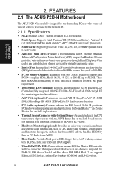
... 128, or 0KB Pipelined Burst Level 2 cache. • Anti-Boot Virus BIOS: Features a programmable BIOS, offering enhanced Advanced Configuration Power Interface (ACPI) support for Sound BlasterTM and Sound Blaster Pro and full-duplex stereo. • Thermal Sensor Connector with Optional Sensor: ...ROM, and LS-120 drives. 8 ASUS P2B-N User's Manual FEATURES 2.1 The ASUS P2B-N Motherboard The ASUS P2B-N is carefully designed for the demanding PC user who wants advanced features processed by Intel or PC Probe from ASUS. • Riser Cards: Provides NLX power, IDE, floppy drive, LAN wake up...
... 128, or 0KB Pipelined Burst Level 2 cache. • Anti-Boot Virus BIOS: Features a programmable BIOS, offering enhanced Advanced Configuration Power Interface (ACPI) support for Sound BlasterTM and Sound Blaster Pro and full-duplex stereo. • Thermal Sensor Connector with Optional Sensor: ...ROM, and LS-120 drives. 8 ASUS P2B-N User's Manual FEATURES 2.1 The ASUS P2B-N Motherboard The ASUS P2B-N is carefully designed for the demanding PC user who wants advanced features processed by Intel or PC Probe from ASUS. • Riser Cards: Provides NLX power, IDE, floppy drive, LAN wake up...
P2B-N User Manual
Page 9
.... • Slim CD-ROM: Supports an optional ASUS slim CD-ROM drive for ASUS' custom designed NLX form factor. 2.1.2 Special Features • ACPI Ready: Advanced Configuration Power Interface (ACPI) provides more Energy Saving Features for configuring...ASUS P2B-N User's Manual 9 FEA TURES Specifications 2. 2. FEATURES • Universal Retention Mechanism: Supports a Pentium® III / II processor packaged in a Single Edge Contact Cartridge (SECC2/SECC) or a CeleronTM processor packaged in the OS, PCs can be used. • Suspend and Go: Suspend-to-RAM provides maximum power...
.... • Slim CD-ROM: Supports an optional ASUS slim CD-ROM drive for ASUS' custom designed NLX form factor. 2.1.2 Special Features • ACPI Ready: Advanced Configuration Power Interface (ACPI) provides more Energy Saving Features for configuring...ASUS P2B-N User's Manual 9 FEA TURES Specifications 2. 2. FEATURES • Universal Retention Mechanism: Supports a Pentium® III / II processor packaged in a Single Edge Contact Cartridge (SECC2/SECC) or a CeleronTM processor packaged in the OS, PCs can be used. • Suspend and Go: Suspend-to-RAM provides maximum power...
P2B-N User Manual
Page 10
... external modem): This allows a computer with a thermal sensor) and system temperatures to ensure proper system configuration and management. 10 ASUS P2B-N User's Manual With this motherboard to critical motherboard components. Voltage specifications are used up to present enormous user interfaces and run large... possible application crashes. The system resource monitor will give the user information on managing their computers from anywhere in 4.6 Power Management Setup). All fans are monitored to ensure stable voltage to be monitored for more memory and hard drive space to...
... external modem): This allows a computer with a thermal sensor) and system temperatures to ensure proper system configuration and management. 10 ASUS P2B-N User's Manual With this motherboard to critical motherboard components. Voltage specifications are used up to present enormous user interfaces and run large... possible application crashes. The system resource monitor will give the user information on managing their computers from anywhere in 4.6 Power Management Setup). All fans are monitored to ensure stable voltage to be monitored for more memory and hard drive space to...
P2B-N User Manual
Page 12
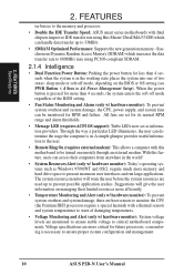
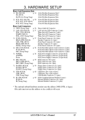
...Ethernet MODEM LAN Controller LANDIS_EN VIO CPU Slot 1 ATI 3D Rage Pro AGP 2X/ Rage IIC VGA Chipset PCI Audio AUDIS_EN Intel PIIX4E Chipset ® P2B-N DIMM Socket 2 (64/72-bit, 168-pin module) DIMM Socket 1 (64/72-bit, 168-pin module) BF0 BF1 BF2 BF3 CDROM Connector... Intel 440BX AGPset 3 2 1 0 Row Keyboard BIOS, RTC, & Multi-I/O ASUS ASIC FS0 FS1 FS2 BUS FREQ SELECT CMOS Power CR2032 3 Volt Cell KB_WAKE CLR_RTC Flash EEPROM (Programmable BIOS) CHASIS_FAN (Grayed items are optional at the time of purchase.) FREQ MULT...
...Ethernet MODEM LAN Controller LANDIS_EN VIO CPU Slot 1 ATI 3D Rage Pro AGP 2X/ Rage IIC VGA Chipset PCI Audio AUDIS_EN Intel PIIX4E Chipset ® P2B-N DIMM Socket 2 (64/72-bit, 168-pin module) DIMM Socket 1 (64/72-bit, 168-pin module) BF0 BF1 BF2 BF3 CDROM Connector... Intel 440BX AGPset 3 2 1 0 Row Keyboard BIOS, RTC, & Multi-I/O ASUS ASIC FS0 FS1 FS2 BUS FREQ SELECT CMOS Power CR2032 3 Volt Cell KB_WAKE CLR_RTC Flash EEPROM (Programmable BIOS) CHASIS_FAN (Grayed items are optional at the time of purchase.) FREQ MULT...
P2B-N User Manual
Page 13
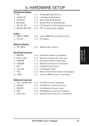
...) Output Connector (15-pin female) 8) GAME p. 34 Joystick or MIDI Connector (15-pin female) Midboard Connectors 1) CPU_, CHASIS_FAN 2) CDROM 3) MODEM 4) AMC 5) JACK_CON p. 34 CPU Fan Power (Two 3-pin blocks) p. 35 CD-ROM Drive Connector (50-3 pins) p. 35 Voice Modem In Connector (4 pins) p. 36 ATI Multimedia Connector (40-3 pin block) p. 36 Back...
...) Output Connector (15-pin female) 8) GAME p. 34 Joystick or MIDI Connector (15-pin female) Midboard Connectors 1) CPU_, CHASIS_FAN 2) CDROM 3) MODEM 4) AMC 5) JACK_CON p. 34 CPU Fan Power (Two 3-pin blocks) p. 35 CD-ROM Drive Connector (50-3 pins) p. 35 Voice Modem In Connector (4 pins) p. 36 ATI Multimedia Connector (40-3 pin block) p. 36 Back...
P2B-N User Manual
Page 14
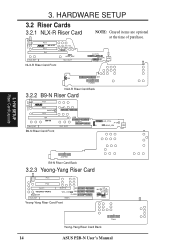
FLOPPY MIC-CON USB FCON IR CIR IDE1 POWER NLX-R Riser Card Back 3.2.2 B9-N Riser Card CHASS_DET PCI3 ® PCI2 WAKEUP PCI1 ISA B9-N NLX_EXT B9-N Riser Card Front IDEA NLX_SLOT IDEB FLOPPY LED_CTRL ... CDIN NLX_EXT SLOT1A IDE2 WOL_CON IDE1 FLOPPY RISER Yeong-Yang Riser Card Front MIC USB IR Panel PWRLED HDD_LED RESET PWRSW SPKR Power Yeong-Yang Riser Card Back 14 ASUS P2B-N User's Manual HARDWARE SETUP 3.2 Riser Cards 3.2.1 NLX-R Riser Card CHASS_DET NLX_EXT PCI2 ® NLX-R PCI1 LAN LEDWOL_CON ISA HEAD_SPK NLX_SLOT NLX-R Riser...
FLOPPY MIC-CON USB FCON IR CIR IDE1 POWER NLX-R Riser Card Back 3.2.2 B9-N Riser Card CHASS_DET PCI3 ® PCI2 WAKEUP PCI1 ISA B9-N NLX_EXT B9-N Riser Card Front IDEA NLX_SLOT IDEB FLOPPY LED_CTRL ... CDIN NLX_EXT SLOT1A IDE2 WOL_CON IDE1 FLOPPY RISER Yeong-Yang Riser Card Front MIC USB IR Panel PWRLED HDD_LED RESET PWRSW SPKR Power Yeong-Yang Riser Card Back 14 ASUS P2B-N User's Manual HARDWARE SETUP 3.2 Riser Cards 3.2.1 NLX-R Riser Card CHASS_DET NLX_EXT PCI2 ® NLX-R PCI1 LAN LEDWOL_CON ISA HEAD_SPK NLX_SLOT NLX-R Riser...
P2B-N User Manual
Page 15
... (Yeong-Yang) 3) FCON (NLX-R) p. 37 HEAD_SPK (NLX-R) LED_CTRL (B9-N) HEAD_SPK (B9-N) PANEL (Yeong-Yang) 4) MIC-CON (NLR-R) p. 38 JP-2K (B9-N) MIC (Yeong-Yang) 5) POWER p. 38 ATXPWR Power 6) IDE1 (NLX-R) p. 39 IDEA, IDEB (B9-N) IDE1, IDE2 (Yeong-Yang) 7) FLOPPY (NLX-R) p. 39 FLOPPY (B9-N) FLOPPY (Yeong-Yang) 8) USB (NLX-R) p. 40 USB1 (B9-N) USB... hardware monitor uses the address 290H-297H, so legacy ISA cards must not use this address or else conflicts will occur. 3. H/W SETUP Riser Card Contents 3. ASUS P2B-N User's Manual 15
... (Yeong-Yang) 3) FCON (NLX-R) p. 37 HEAD_SPK (NLX-R) LED_CTRL (B9-N) HEAD_SPK (B9-N) PANEL (Yeong-Yang) 4) MIC-CON (NLR-R) p. 38 JP-2K (B9-N) MIC (Yeong-Yang) 5) POWER p. 38 ATXPWR Power 6) IDE1 (NLX-R) p. 39 IDEA, IDEB (B9-N) IDE1, IDE2 (Yeong-Yang) 7) FLOPPY (NLX-R) p. 39 FLOPPY (B9-N) FLOPPY (Yeong-Yang) 8) USB (NLX-R) p. 40 USB1 (B9-N) USB... hardware monitor uses the address 290H-297H, so legacy ISA cards must not use this address or else conflicts will occur. 3. H/W SETUP Riser Card Contents 3. ASUS P2B-N User's Manual 15
P2B-N User Manual
Page 17
...components by the edges and try not to change your hands to a safely grounded object or to a metal object, such as the power supply case. 3. Setup the BIOS Software 3.4 Motherboard Settings This section explains in detail how to touch the IC chips, leads or...cards contain very delicate Integrated Circuit (IC) chips. Place components on a grounded antistatic pad or on the inside. 2. H/W SETUP Motherboard Settings ASUS P2B-N User's Manual 17 Install Expansion Cards 5. To protect them against damage from the system. 3. HARDWARE SETUP 3.3 Hardware Setup Procedure Before using...
...components by the edges and try not to change your hands to a safely grounded object or to a metal object, such as the power supply case. 3. Setup the BIOS Software 3.4 Motherboard Settings This section explains in detail how to touch the IC chips, leads or...cards contain very delicate Integrated Circuit (IC) chips. Place components on a grounded antistatic pad or on the inside. 2. H/W SETUP Motherboard Settings ASUS P2B-N User's Manual 17 Install Expansion Cards 5. To protect them against damage from the system. 3. HARDWARE SETUP 3.3 Hardware Setup Procedure Before using...
P2B-N User Manual
Page 19
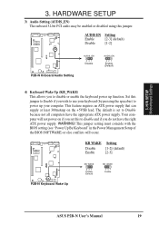
...) or else conflicts will not power on the +5VSB lead. H/W SETUP Motherboard Settings 3. The default is set this jumper. KB WAKE Setting Disable Enable [1-2] (default) [2-3] P2B-N Keyboard Wake Up KB_WAKE 321 Disable (Default) KB_WAKE 321 Enable ASUS P2B-N User's Manual 19 Your computer... will occur. Set this jumper to use your computer. This feature requires an ATX power supply that can supply at least 300mAmp...
...) or else conflicts will not power on the +5VSB lead. H/W SETUP Motherboard Settings 3. The default is set this jumper. KB WAKE Setting Disable Enable [1-2] (default) [2-3] P2B-N Keyboard Wake Up KB_WAKE 321 Disable (Default) KB_WAKE 321 Enable ASUS P2B-N User's Manual 19 Your computer... will occur. Set this jumper to use your computer. This feature requires an ATX power supply that can supply at least 300mAmp...
P2B-N User Manual
Page 21
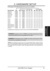
...not needed for the Pentium III / II / Celeron processor because it sends VID signals directly to the onboard power controller. 3. Multiple) BF0 BF1 BF2 BF3 [2-3] [2-3] [2-3] [1-2] [1-2] [1-2] [1-2] [2-3] [2-3] [1-2] [1-2] [2-3]... [1-2] [2-3] [2-3] [1-2] [2-3] [2-3] [2-3] [1-2] [1-2] [1-2] [1-2] [2-3] [2-3] [1-2] [1-2] [2-3] [1-2] [2-3] [1-2] [2-3] [2-3] [2-3] [1-2] [2-3] [2-3] [2-3] [1-2] [2-3] For updated processor settings, please visit ASUS' web site (see ASUS CONTACT INFORMATION). WARNING! H/W SETUP Motherboard Settings ASUS P2B-N User's Manual 21 Bus Freq. 6.0x 100MHz 5.5x 100MHz...
...not needed for the Pentium III / II / Celeron processor because it sends VID signals directly to the onboard power controller. 3. Multiple) BF0 BF1 BF2 BF3 [2-3] [2-3] [2-3] [1-2] [1-2] [1-2] [1-2] [2-3] [2-3] [1-2] [1-2] [2-3]... [1-2] [2-3] [2-3] [1-2] [2-3] [2-3] [2-3] [1-2] [1-2] [1-2] [1-2] [2-3] [2-3] [1-2] [1-2] [2-3] [1-2] [2-3] [1-2] [2-3] [2-3] [2-3] [1-2] [2-3] [2-3] [2-3] [1-2] [2-3] For updated processor settings, please visit ASUS' web site (see ASUS CONTACT INFORMATION). WARNING! H/W SETUP Motherboard Settings ASUS P2B-N User's Manual 21 Bus Freq. 6.0x 100MHz 5.5x 100MHz...
P2B-N User Manual
Page 23
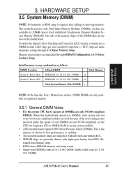
3. Memory speed setup is recommended through 4.5 Chipset Features Setup. ASUS P2B-N User's Manual 23 This motherboard uses only Dual Inline Memory Modules (DIMMs). ... available as registered memory. 3.5.1 General DIMM Notes • For the system CPU bus to ensure system stability. • ASUS motherboards support SPD (Serial Presence Detect) DIMMs. This is required after adding or removing memory. Install memory in 4.5 Chipset...) NOTE: No hardware or BIOS setup is the memory of choice for 3.3Volt (power level) unbuffered Synchronous Dynamic Random Access Memory (SDRAM).
3. Memory speed setup is recommended through 4.5 Chipset Features Setup. ASUS P2B-N User's Manual 23 This motherboard uses only Dual Inline Memory Modules (DIMMs). ... available as registered memory. 3.5.1 General DIMM Notes • For the system CPU bus to ensure system stability. • ASUS motherboards support SPD (Serial Presence Detect) DIMMs. This is required after adding or removing memory. Install memory in 4.5 Chipset...) NOTE: No hardware or BIOS setup is the memory of choice for 3.3Volt (power level) unbuffered Synchronous Dynamic Random Access Memory (SDRAM).
P2B-N User Manual
Page 30
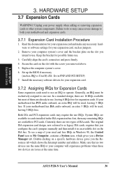
.... Set up the BIOS if necessary (such as jumpers. 2. The original ISA expansion card design, now referred to both your power supply when adding or removing expansion cards or other system components. ASUS P2B-N User's Manual 30 Read the documentation for your motherboard has ISA audio onboard, an extra 3 IRQs will be used...
.... Set up the BIOS if necessary (such as jumpers. 2. The original ISA expansion card design, now referred to both your power supply when adding or removing expansion cards or other system components. ASUS P2B-N User's Manual 30 Read the documentation for your motherboard has ISA audio onboard, an extra 3 IRQs will be used...

P2B-N User Manual
Page 32
...port and choose the IRQ through Onboard Parallel Port in 4.5 Chipset Features Setup. HARDWARE SETUP 3.8 External Connectors WARNING! These are used for connectors or power sources. H/W SETUP Connectors 2) Serial Port Connectors (9-pin COM1 and COM2) The two serial ports can be less than 15 cm (6 in.) ... red stripe to Pin 1 on the connectors. Pin 1 is usually on the side closest to the power connector on floppy disk drives. COM 2 COM 1 Serial Ports (9-pin male) 32 ASUS P2B-N User's Manual IMPORTANT: Ribbon cables should always be on the opposite side on hard drives and CD...
...port and choose the IRQ through Onboard Parallel Port in 4.5 Chipset Features Setup. HARDWARE SETUP 3.8 External Connectors WARNING! These are used for connectors or power sources. H/W SETUP Connectors 2) Serial Port Connectors (9-pin COM1 and COM2) The two serial ports can be less than 15 cm (6 in.) ... red stripe to Pin 1 on the connectors. Pin 1 is usually on the side closest to the power connector on floppy disk drives. COM 2 COM 1 Serial Ports (9-pin male) 32 ASUS P2B-N User's Manual IMPORTANT: Ribbon cables should always be on the opposite side on hard drives and CD...
P2B-N User Manual
Page 34
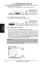
... of the expansion slots. Connect the fan's plug to go across the CPU and onboard heatsinks. CPU Fan Power Rotation +12 Volt Ground R Rotation +12 Volt Ground Chassis Fan Power P2B-N 12-Volt Cooling Fan Power 34 ASUS P2B-N User's Manual VGA Monitor (15-pin female) 8) Joystick/MIDI Connector (15-pin GAME) This connector is no...
... of the expansion slots. Connect the fan's plug to go across the CPU and onboard heatsinks. CPU Fan Power Rotation +12 Volt Ground R Rotation +12 Volt Ground Chassis Fan Power P2B-N 12-Volt Cooling Fan Power 34 ASUS P2B-N User's Manual VGA Monitor (15-pin female) 8) Joystick/MIDI Connector (15-pin GAME) This connector is no...

P2B-N User Manual
Page 37
... 1 4 Pin 1 The front panel display & buttons connect to flash during transfer activity between the network and the computer. Power Switch - H/W SETUP Connectors 3. Power LED YEONG-YANG Yeong-Yang (Front) Front Panel Display and Button Connector 1+ + + + ASUS P2B-N User's Manual 37 HARDWARE SETUP 2) LAN Activity Connectors (2-pin LAN_LED & 3-pin WOL_CON) These connectors support Local Area...
... 1 4 Pin 1 The front panel display & buttons connect to flash during transfer activity between the network and the computer. Power Switch - H/W SETUP Connectors 3. Power LED YEONG-YANG Yeong-Yang (Front) Front Panel Display and Button Connector 1+ + + + ASUS P2B-N User's Manual 37 HARDWARE SETUP 2) LAN Activity Connectors (2-pin LAN_LED & 3-pin WOL_CON) These connectors support Local Area...

P2B-N User Manual
Page 38
... Volts +5.0 Volts -5.0 Volts Ground Ground Ground Power Supply On Ground -12.0 Volts +3.3 Volts B9-N (Back) +12.0 Volts +5V Standby Power Good Ground +5.0 Volts Ground +5.0 Volts Ground +3.3 Volts +3.3 Volts Yeong-Yang (Back) NLX Power Connector NLX Power Supply Connector 38 ASUS P2B-N User's Manual HARDWARE SETUP 4) Front Panel ...to the riser card through a ribbon cable Yeong-Yang (Front) YEONG-YANG Front Panel Microphone Jack 5) NLX Power Supply Connector (20-pin block) This connector connects to an NLX power supply. IMPORTANT: Make sure that the pins are aligned. The plug from the...
... Volts +5.0 Volts -5.0 Volts Ground Ground Ground Power Supply On Ground -12.0 Volts +3.3 Volts B9-N (Back) +12.0 Volts +5V Standby Power Good Ground +5.0 Volts Ground +5.0 Volts Ground +3.3 Volts +3.3 Volts Yeong-Yang (Back) NLX Power Connector NLX Power Supply Connector 38 ASUS P2B-N User's Manual HARDWARE SETUP 4) Front Panel ...to the riser card through a ribbon cable Yeong-Yang (Front) YEONG-YANG Front Panel Microphone Jack 5) NLX Power Supply Connector (20-pin block) This connector connects to an NLX power supply. IMPORTANT: Make sure that the pins are aligned. The plug from the...

P2B-N User Manual
Page 40
...Front) 1 5 1: +5 Volt 4: GND 2: (no connection) 5: IRTX 3: IRRX IRTX GND IRRX +5V FIR/(NC) Infrared Module / Infrared Module Connector 40 ASUS P2B-N User's Manual NLX-R (Back) ® B9-N B9-N (Front) The module sends data through the front panel infrared lense. If you have the Yeong-Yang ... set . An optional consumer infrared (CIR) set to Enabled in 4.6 Power Management Setup must be Enabled to use with COM2 or IrDA. Power Up By Keyboard in 4.7 PNP and PCI Setup to use Consumer Infrared (CIR) power up. HARDWARE SETUP 8) USB Ports (Two 4-pin Female Sockets) & ...
...Front) 1 5 1: +5 Volt 4: GND 2: (no connection) 5: IRTX 3: IRRX IRTX GND IRRX +5V FIR/(NC) Infrared Module / Infrared Module Connector 40 ASUS P2B-N User's Manual NLX-R (Back) ® B9-N B9-N (Front) The module sends data through the front panel infrared lense. If you have the Yeong-Yang ... set . An optional consumer infrared (CIR) set to Enabled in 4.6 Power Management Setup must be Enabled to use with COM2 or IrDA. Power Up By Keyboard in 4.7 PNP and PCI Setup to use Consumer Infrared (CIR) power up. HARDWARE SETUP 8) USB Ports (Two 4-pin Female Sockets) & ...


