
P2B-LS User Manual
Page 1
R P2B-L / P2B-S / P2B-LS Pentium® II Motherboards USER'S MANUAL Special Features ASUS P2B-L (power supply must provide at least 720mA on the +5VSB) • Intel 82558 LAN Chipset • Wake-On-LAN ASUS P2B-S • Adaptec 7890 SCSI Chipset • Adaptec 3860 SCSI Transceiver ASUS P2B-LS (power supply must provide at least 720mA on the +5VSB) • Intel 82558 LAN Chipset • Wake-On-LAN • Adaptec 7890 SCSI Chipset • Adaptec 3860 SCSI Transceiver
R P2B-L / P2B-S / P2B-LS Pentium® II Motherboards USER'S MANUAL Special Features ASUS P2B-L (power supply must provide at least 720mA on the +5VSB) • Intel 82558 LAN Chipset • Wake-On-LAN ASUS P2B-S • Adaptec 7890 SCSI Chipset • Adaptec 3860 SCSI Transceiver ASUS P2B-LS (power supply must provide at least 720mA on the +5VSB) • Intel 82558 LAN Chipset • Wake-On-LAN • Adaptec 7890 SCSI Chipset • Adaptec 3860 SCSI Transceiver
P2B-LS User Manual
Page 2
...purchaser for backup purposes, without intent to the owners' benefit, without the express written permission of ASUSTeK COMPUTER INC. ("ASUS"). ASUS ASSUMES NO RESPONSIBILITY OR LIABILITY FOR ANY ERRORS OR INACCURACIES THAT MAY APPEAR IN THIS MANUAL, INCLUDING THE PRODUCTS AND ...AT ANY TIME WITHOUT NOTICE, AND SHOULD NOT BE CONSTRUED AS A COMMITMENT BY ASUS. All Rights Reserved. Product Name: ASUS P2B-L/P2B-S/P2B-LS Manual Revision: 1.06 E265 Release Date: August 1998 2 ASUS P2B-L/P2B-S/P2B-LS User's Manual Manual updates are represented by the third digit in this manual, ...
...purchaser for backup purposes, without intent to the owners' benefit, without the express written permission of ASUSTeK COMPUTER INC. ("ASUS"). ASUS ASSUMES NO RESPONSIBILITY OR LIABILITY FOR ANY ERRORS OR INACCURACIES THAT MAY APPEAR IN THIS MANUAL, INCLUDING THE PRODUCTS AND ...AT ANY TIME WITHOUT NOTICE, AND SHOULD NOT BE CONSTRUED AS A COMMITMENT BY ASUS. All Rights Reserved. Product Name: ASUS P2B-L/P2B-S/P2B-LS Manual Revision: 1.06 E265 Release Date: August 1998 2 ASUS P2B-L/P2B-S/P2B-LS User's Manual Manual updates are represented by the third digit in this manual, ...

P2B-LS User Manual
Page 3
...: +886-2-2894-3449 Email: info@asus.com.tw Technical Support Fax: +886-2-2895-9254 BBS: +886-2-2896-4667 Email: tsd@asus.com.tw WWW: www.asus.com.tw FTP: ftp.asus.com.tw/pub/ASUS ASUS COMPUTER INTERNATIONAL Marketing Address: 6737 Mowry...ASUS ASUS COMPUTER GmbH Marketing Address: Harkort Str. 25, 40880 Ratingen, BRD, Germany Telephone: 49-2102-445011 Fax: 49-2102-442066 Email: info-ger@asus.com.tw Technical Support Hotline: 49-2102-499712 BBS: 49-2102-448690 Email: tsd-ger@asus.com.tw WWW: www.asuscom.de FTP: ftp.asuscom.de/pub/ASUSCOM ASUS P2B-L/P2B-S/P2B-LS...
...: +886-2-2894-3449 Email: info@asus.com.tw Technical Support Fax: +886-2-2895-9254 BBS: +886-2-2896-4667 Email: tsd@asus.com.tw WWW: www.asus.com.tw FTP: ftp.asus.com.tw/pub/ASUS ASUS COMPUTER INTERNATIONAL Marketing Address: 6737 Mowry...ASUS ASUS COMPUTER GmbH Marketing Address: Harkort Str. 25, 40880 Ratingen, BRD, Germany Telephone: 49-2102-445011 Fax: 49-2102-442066 Email: info-ger@asus.com.tw Technical Support Hotline: 49-2102-499712 BBS: 49-2102-448690 Email: tsd-ger@asus.com.tw WWW: www.asuscom.de FTP: ftp.asuscom.de/pub/ASUSCOM ASUS P2B-L/P2B-S/P2B-LS...
P2B-LS User Manual
Page 4
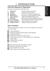
...Cards and Hardware Monitor 25 Accelerated Graphics Port 25 5. INTRODUCTION How this Manual is Organized 7 Item Checklist 7 II. INSTALLATION ASUS P2B-L/P2B-S/P2B-LS Motherboard Layout 10 Installation Steps 12 1. System Memory (DIMM 17 DIMM Memory Installation Procedures 18 3. BIOS Setup 39 Load ... Features Setup 46 Details of Chipset Features Setup 46 Power Management Setup 49 Details of Power Management Setup 49 4 ASUS P2B-L/P2B-S/P2B-LS User's Manual External Connectors 26 Power Connection Procedures 35 IV. BIOS SOFTWARE Main Menu 36 Flash Memory Writer Utility...
...Cards and Hardware Monitor 25 Accelerated Graphics Port 25 5. INTRODUCTION How this Manual is Organized 7 Item Checklist 7 II. INSTALLATION ASUS P2B-L/P2B-S/P2B-LS Motherboard Layout 10 Installation Steps 12 1. System Memory (DIMM 17 DIMM Memory Installation Procedures 18 3. BIOS Setup 39 Load ... Features Setup 46 Details of Chipset Features Setup 46 Power Management Setup 49 Details of Power Management Setup 49 4 ASUS P2B-L/P2B-S/P2B-LS User's Manual External Connectors 26 Power Connection Procedures 35 IV. BIOS SOFTWARE Main Menu 36 Flash Memory Writer Utility...
P2B-LS User Manual
Page 5
... 64 DOS and Windows 3.1 Setup for DOS/Windows 3.1x Users 83 DOS Formatting Utilities 84 Low-level Formatter (scsifmt 84 Formatter and Partitioner (afdisk 85 ASUS P2B-L/P2B-S/P2B-LS User's Manual 5 Support CD Support CD Main Menu 58 Main Menu Selections 59 Other CD Directories 59 VI. ADAPTEC SCSI SELECT Configuring the SCSI Adapter...
... 64 DOS and Windows 3.1 Setup for DOS/Windows 3.1x Users 83 DOS Formatting Utilities 84 Low-level Formatter (scsifmt 84 Formatter and Partitioner (afdisk 85 ASUS P2B-L/P2B-S/P2B-LS User's Manual 5 Support CD Support CD Main Menu 58 Main Menu Selections 59 Other CD Directories 59 VI. ADAPTEC SCSI SELECT Configuring the SCSI Adapter...

P2B-LS User Manual
Page 6
... responsible for a Class B digital device, pursuant to comply with FCC Rules Part 15. This equipment has been tested and found to Part 15 of Communications. 6 ASUS P2B-L/P2B-S/P2B-LS User's Manual
... responsible for a Class B digital device, pursuant to comply with FCC Rules Part 15. This equipment has been tested and found to Part 15 of Communications. 6 ASUS P2B-L/P2B-S/P2B-LS User's Manual
P2B-LS User Manual
Page 7
... IV. Instructions on the built-in LAN controller (optional) Adaptec SCSI Select utility (optional) Adaptec EZ-SCSI utility (optional) Item Checklist Check that your retailer. (1) ASUS Motherboard (1) Retention mechanism & heatsink support for CPU and heatsink (2) Attach mount bridges (1) IDE ribbon cable for master and slave drives (1) Floppy ribbon cable for (1) 5.25inch...-pin Ultra2 SCSI cable with terminator (optional) 68-pin Fast & Wide SCSI cable (optional) 50-pin Fast SCSI cable (optional) Network condition connector module (optional) ASUS P2B-L/P2B-S/P2B-LS User's Manual 7
... IV. Instructions on the built-in LAN controller (optional) Adaptec SCSI Select utility (optional) Adaptec EZ-SCSI utility (optional) Item Checklist Check that your retailer. (1) ASUS Motherboard (1) Retention mechanism & heatsink support for CPU and heatsink (2) Attach mount bridges (1) IDE ribbon cable for master and slave drives (1) Floppy ribbon cable for (1) 5.25inch...-pin Ultra2 SCSI cable with terminator (optional) 68-pin Fast & Wide SCSI cable (optional) 50-pin Fast SCSI cable (optional) Network condition connector module (optional) ASUS P2B-L/P2B-S/P2B-LS User's Manual 7
P2B-LS User Manual
Page 8
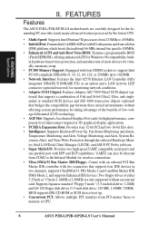
...Monitoring and Alert, System Resources Alert, and Virus Write Protection through the onboard Hardware Monitor, Intel LANDesk Client Manager (LDCM), and ASUS PC Probe software. • Super Multi-I /O subsystems and front-side bus (FSB) platform, which boosts the traditional 66-MHz...without an external card. II. BIOS supports IDE CD-ROM or SCSI device boot-up to CPU. 8 ASUS P2B-L/P2B-S/P2B-LS User's Manual FEATURES Features The ASUS P2B-L/P2B-S/P2B-LS motherboards are also supported without affecting system performance by the fastest CPU. • Multi-Speed: Supports Intel Pentium...
...Monitoring and Alert, System Resources Alert, and Virus Write Protection through the onboard Hardware Monitor, Intel LANDesk Client Manager (LDCM), and ASUS PC Probe software. • Super Multi-I /O subsystems and front-side bus (FSB) platform, which boosts the traditional 66-MHz...without an external card. II. BIOS supports IDE CD-ROM or SCSI device boot-up to CPU. 8 ASUS P2B-L/P2B-S/P2B-LS User's Manual FEATURES Features The ASUS P2B-L/P2B-S/P2B-LS motherboards are also supported without affecting system performance by the fastest CPU. • Multi-Speed: Supports Intel Pentium...
P2B-LS User Manual
Page 9
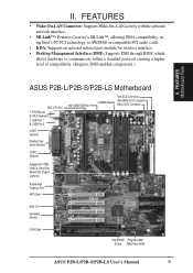
FEATURES Motherboard Parts ASUS P2B-L/P2B-S/P2B-LS Motherboard SEC CPU Slot T: PS/2 Mouse B: PS/2 Keyboard T: USB Port 1 B: USB Port 2 COM 1 (Bottom) Parallel (Top) Serial (Bottom) COM 2 (Bottom) Intel 440BX AGPset Fast-...-7890 Ultra2 & Ultra-Fast/ Wide SCSI Chipset (optional) Accelerated Graphics Port 4PCI Slots Multi-I/O Hardware Monitor 2 ISA Slots Intel PIIX4E Programmable PCIset 2Mbit Flash ROM ASUS P2B-L/P2B-S/P2B-LS User's Manual 9 II. FEATURES • Wake-On-LAN Connector: Supports Wake-On-LAN activity with the optional network interface. • SB-Link™: Features ...
FEATURES Motherboard Parts ASUS P2B-L/P2B-S/P2B-LS Motherboard SEC CPU Slot T: PS/2 Mouse B: PS/2 Keyboard T: USB Port 1 B: USB Port 2 COM 1 (Bottom) Parallel (Top) Serial (Bottom) COM 2 (Bottom) Intel 440BX AGPset Fast-...-7890 Ultra2 & Ultra-Fast/ Wide SCSI Chipset (optional) Accelerated Graphics Port 4PCI Slots Multi-I/O Hardware Monitor 2 ISA Slots Intel PIIX4E Programmable PCIset 2Mbit Flash ROM ASUS P2B-L/P2B-S/P2B-LS User's Manual 9 II. FEATURES • Wake-On-LAN Connector: Supports Wake-On-LAN activity with the optional network interface. • SB-Link™: Features ...
P2B-LS User Manual
Page 10
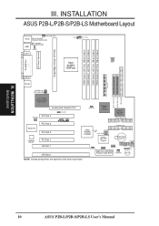
... BIOS) CHA_FAN PANEL IDELED Combine IR Speaker NOTE: Greyed components are optional at the time of purchase. III. INSTALLATION Board Layout 10 ASUS P2B-L/P2B-S/P2B-LS User's Manual FS0 68 34 34 68 COM 2 RJ-45 FLOPPY LAN Activity LED Connector 35 1 35 1 50-Pin SCSI 1... ISA Slot 1 ISA Slot 2 SCSI_EN Adaptec SCSI Chipset Adaptec AIC-3860 Chipset SECONDARY IDE 1 PRIMARY IDE Intel PIIX4E Chipset CLRTC 1 Freq. INSTALLATION ASUS P2B-L/P2B-S/P2B-LS Motherboard Layout DIMM Socket 0 (64/72 bit, 168 pin module) DIMM Socket 1 (64/72 bit, 168 pin module) DIMM Socket 2 (...
... BIOS) CHA_FAN PANEL IDELED Combine IR Speaker NOTE: Greyed components are optional at the time of purchase. III. INSTALLATION Board Layout 10 ASUS P2B-L/P2B-S/P2B-LS User's Manual FS0 68 34 34 68 COM 2 RJ-45 FLOPPY LAN Activity LED Connector 35 1 35 1 50-Pin SCSI 1... ISA Slot 1 ISA Slot 2 SCSI_EN Adaptec SCSI Chipset Adaptec AIC-3860 Chipset SECONDARY IDE 1 PRIMARY IDE Intel PIIX4E Chipset CLRTC 1 Freq. INSTALLATION ASUS P2B-L/P2B-S/P2B-LS Motherboard Layout DIMM Socket 0 (64/72 bit, 168 pin module) DIMM Socket 1 (64/72 bit, 168 pin module) DIMM Socket 2 (...

P2B-LS User Manual
Page 11
... onboard hardware monitor uses the address 290H-297H so legacy ISA cards must not use this address, otherwise conflicts will occur. INSTALLATION Board Layout III. ASUS P2B-L/P2B-S/P2B-LS User's Manual 11 III.
... onboard hardware monitor uses the address 290H-297H so legacy ISA cards must not use this address, otherwise conflicts will occur. INSTALLATION Board Layout III. ASUS P2B-L/P2B-S/P2B-LS User's Manual 11 III.
P2B-LS User Manual
Page 12
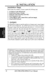
INSTALLATION Installation Steps Before using your computer. 1. Jumpers Several hardware settings are separated from the system. 12 ASUS P2B-L/P2B-S/P2B-LS User's Manual The jumpers will also be sharing pins from static electricity, you should follow some precautions whenever you work on your computer, you do ...
INSTALLATION Installation Steps Before using your computer. 1. Jumpers Several hardware settings are separated from the system. 12 ASUS P2B-L/P2B-S/P2B-LS User's Manual The jumpers will also be sharing pins from static electricity, you should follow some precautions whenever you work on your computer, you do ...
P2B-LS User Manual
Page 13
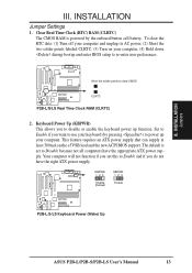
...pressing ) to re-enter user preferences. INSTALLATION Jumpers III. INSTALLATION Jumper Settings 1. KBPWR 123 Disable (Default) KBPWR 123 Enable R P2B-L/S/LS Keyboard Power (Wake) Up ASUS P2B-L/P2B-S/P2B-LS User's Manual 13 Clear Real Time Clock (RTC) RAM (CLRTC) The CMOS RAM is set this to Disable because not all computers... and the new ACPI BIOS support. Your computer will not function if you set to Enable and if you to clear CMOS R CLRTC P2B-L/S/LS Real Time Clock RAM (CLRTC) 2. Keyboard Power Up (KBPWR) This allows you do not have the appropriate ATX power supply. To ...
...pressing ) to re-enter user preferences. INSTALLATION Jumpers III. INSTALLATION Jumper Settings 1. KBPWR 123 Disable (Default) KBPWR 123 Enable R P2B-L/S/LS Keyboard Power (Wake) Up ASUS P2B-L/P2B-S/P2B-LS User's Manual 13 Clear Real Time Clock (RTC) RAM (CLRTC) The CMOS RAM is set this to Disable because not all computers... and the new ACPI BIOS support. Your computer will not function if you set to Enable and if you to clear CMOS R CLRTC P2B-L/S/LS Real Time Clock RAM (CLRTC) 2. Keyboard Power Up (KBPWR) This allows you do not have the appropriate ATX power supply. To ...

P2B-LS User Manual
Page 14
...3. COMBINE (Default) IDELED and SCSILED activity are separate COMBINE IDELED includes SCSILED activity P2B-L/S/LS IDE/SCSI Device Activity LED Selection 14 ASUS P2B-L/P2B-S/P2B-LS User's Manual LAN_EN 1 2 3 Enable (Default) LAN_EN 1 2 3 Disable P2B-L/S/LS Onboard LAN Setting 4. Onboard LAN Setting (LAN_EN) The onboard Intel 10/100 Fast... the IDE and SCSI activity into the IDELED. SCSI_EN 1 2 3 Enable (Default) SCSI_EN 1 2 3 Disable P2B-L/S/LS Onboard SCSI Setting 5. IDE/SCSI Device Activity LED Selection (COMBINE) The IDE and SCSI Activity LEDs normally has separate connections.
...3. COMBINE (Default) IDELED and SCSILED activity are separate COMBINE IDELED includes SCSILED activity P2B-L/S/LS IDE/SCSI Device Activity LED Selection 14 ASUS P2B-L/P2B-S/P2B-LS User's Manual LAN_EN 1 2 3 Enable (Default) LAN_EN 1 2 3 Disable P2B-L/S/LS Onboard LAN Setting 4. Onboard LAN Setting (LAN_EN) The onboard Intel 10/100 Fast... the IDE and SCSI activity into the IDELED. SCSI_EN 1 2 3 Enable (Default) SCSI_EN 1 2 3 Disable P2B-L/S/LS Onboard SCSI Setting 5. IDE/SCSI Device Activity LED Selection (COMBINE) The IDE and SCSI Activity LEDs normally has separate connections.

P2B-LS User Manual
Page 15
It may result in conjunction with the CPU Bus Frequency. ASUS P2B-L/P2B-S/P2B-LS User's Manual 15 INSTALLATION 6. R P2B-L/S/LS CPU Settings 123 123 123 123 123 123 123 123 123 BF3 BF2 BF1 BF0 2.0x (2/1) 2.5x (5/2) 3.0x (3/1) 3.5x (7/2) 4.0x (4/1) 4.5x (9/2) 5.0x (5/1) 5.5x (11/2) 6.0x (6/1) ...
It may result in conjunction with the CPU Bus Frequency. ASUS P2B-L/P2B-S/P2B-LS User's Manual 15 INSTALLATION 6. R P2B-L/S/LS CPU Settings 123 123 123 123 123 123 123 123 123 BF3 BF2 BF1 BF0 2.0x (2/1) 2.5x (5/2) 3.0x (3/1) 3.5x (7/2) 4.0x (4/1) 4.5x (9/2) 5.0x (5/1) 5.5x (11/2) 6.0x (6/1) ...

P2B-LS User Manual
Page 16
(This page was intentionally left blank.) 16 ASUS P2B-L/P2B-S/P2B-LS User's Manual
(This page was intentionally left blank.) 16 ASUS P2B-L/P2B-S/P2B-LS User's Manual
P2B-LS User Manual
Page 17
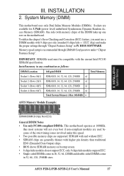
..., 256MB x1 Socket 3 (Rows 4&5) SDRAM 8, 16, 32, 64, 128, 256MB x1 Socket 4 (Rows 6&7) SDRAM 8, 16, 32, 64, 128, 256MB x1 Total System Memory (Max 1024MB) = ASUS Memory Module Example: III. INSTALLATION System Memory SDRAM DIMM (8 chips, Non-ECC) General DIMM Notes • Use only PC100-compliant DIMMs. This motherboard operates at... the chipset's Error Checking and Correction (ECC) feature, you must be compatible with memory chips) of the strict timing issues involved under "Chipset Features Setup". ASUS P2B-L/P2B-S/P2B-LS User's Manual 17
..., 256MB x1 Socket 3 (Rows 4&5) SDRAM 8, 16, 32, 64, 128, 256MB x1 Socket 4 (Rows 6&7) SDRAM 8, 16, 32, 64, 128, 256MB x1 Total System Memory (Max 1024MB) = ASUS Memory Module Example: III. INSTALLATION System Memory SDRAM DIMM (8 chips, Non-ECC) General DIMM Notes • Use only PC100-compliant DIMMs. This motherboard operates at... the chipset's Error Checking and Correction (ECC) feature, you must be compatible with memory chips) of the strict timing issues involved under "Chipset Features Setup". ASUS P2B-L/P2B-S/P2B-LS User's Manual 17

P2B-LS User Manual
Page 18
...only fit in the orientation as shown. DRAM SIMM modules have a higher pin density. 20 Pins 60 Pins 88 Pins Lock (FRONT) P2B-L/S/LS 168-Pin DIMM Memory Sockets The DIMMs must tell your retailer the correct DIMM type before purchasing. Because the number of pins are different ...and also to prevent the wrong type from being inserted into the DIMM slot on both sides. This motherboard supports four clock signals. 18 ASUS P2B-L/P2B-S/P2B-LS User's Manual R III. SDRAM DIMMs have different pin contacts on each side and therefore have the same pin contacts on the motherboard. INSTALLATION...
...only fit in the orientation as shown. DRAM SIMM modules have a higher pin density. 20 Pins 60 Pins 88 Pins Lock (FRONT) P2B-L/S/LS 168-Pin DIMM Memory Sockets The DIMMs must tell your retailer the correct DIMM type before purchasing. Because the number of pins are different ...and also to prevent the wrong type from being inserted into the DIMM slot on both sides. This motherboard supports four clock signals. 18 ASUS P2B-L/P2B-S/P2B-LS User's Manual R III. SDRAM DIMMs have different pin contacts on each side and therefore have the same pin contacts on the motherboard. INSTALLATION...

P2B-LS User Manual
Page 19
... motherboard provides a Single Edge Contact (SEC) slot for the Support Top Bar Heatsink Support Base/Top Bar (Items 4-7) Pentium II Processor Heatsink (Item 8) CPU (Item 9) ASUS P2B-L/P2B-S/P2B-LS User's Manual 19 You may be on the bottom. INSTALLATION CPU III. Without sufficient circulation, the processor could overheat and damage both the processor and...
... motherboard provides a Single Edge Contact (SEC) slot for the Support Top Bar Heatsink Support Base/Top Bar (Items 4-7) Pentium II Processor Heatsink (Item 8) CPU (Item 9) ASUS P2B-L/P2B-S/P2B-LS User's Manual 19 You may be on the bottom. INSTALLATION CPU III. Without sufficient circulation, the processor could overheat and damage both the processor and...

P2B-LS User Manual
Page 20
... one side of the AGPset). INSTALLATION CPU Installing the Pentium II Processor 1. Do not overtighten the captive nuts. Lock holes Captive nut Captive nut 20 ASUS P2B-L/P2B-S/P2B-LS User's Manual III. TIP: Orient the mechanism's lock holes toward the motherboard's chipset (see motherboard layout for the location of the slot and that the...
... one side of the AGPset). INSTALLATION CPU Installing the Pentium II Processor 1. Do not overtighten the captive nuts. Lock holes Captive nut Captive nut 20 ASUS P2B-L/P2B-S/P2B-LS User's Manual III. TIP: Orient the mechanism's lock holes toward the motherboard's chipset (see motherboard layout for the location of the slot and that the...


