P2B-LS User Manual
Page 2
...of Intel Corporation. • IBM and OS/2 are registered trademarks of ASUSTeK COMPUTER INC. ("ASUS"). ASUS ASSUMES NO RESPONSIBILITY OR LIABILITY FOR ANY ERRORS OR INACCURACIES THAT MAY APPEAR IN THIS MANUAL, INCLUDING...BIOS, drivers, or product release information, contact ASUS at http://www.asus.com.tw or through any means, except documentation kept by ASUS; or (2) the serial number of Adobe Systems Incorporated. Manual updates are both printed on the following page. Product Name: ASUS P2B-L/P2B-S/P2B-LS Manual Revision: 1.06 E265 Release Date: August 1998 2 ASUS P2B-L/P2B-S/P2B-LS...
...of Intel Corporation. • IBM and OS/2 are registered trademarks of ASUSTeK COMPUTER INC. ("ASUS"). ASUS ASSUMES NO RESPONSIBILITY OR LIABILITY FOR ANY ERRORS OR INACCURACIES THAT MAY APPEAR IN THIS MANUAL, INCLUDING...BIOS, drivers, or product release information, contact ASUS at http://www.asus.com.tw or through any means, except documentation kept by ASUS; or (2) the serial number of Adobe Systems Incorporated. Manual updates are both printed on the following page. Product Name: ASUS P2B-L/P2B-S/P2B-LS Manual Revision: 1.06 E265 Release Date: August 1998 2 ASUS P2B-L/P2B-S/P2B-LS...
P2B-LS User Manual
Page 4
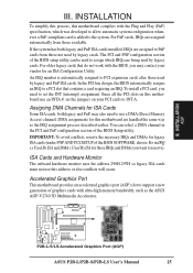
...Monitor 25 Accelerated Graphics Port 25 5. INTRODUCTION How this Manual is Organized 7 Item Checklist 7 II. INSTALLATION ASUS P2B-L/P2B-S/P2B-LS Motherboard Layout 10 Installation Steps 12 1. BIOS SOFTWARE Main Menu 36 Flash Memory Writer Utility 36 Managing and Updating Your Motherboard...40 Details of Standard CMOS Setup 40 BIOS Features Setup 43 Details of BIOS Features Setup 43 Chipset Features Setup 46 Details of Chipset Features Setup 46 Power Management Setup 49 Details of Power Management Setup 49 4 ASUS P2B-L/P2B-S/P2B-LS User's Manual External Connectors 26 Power...
...Monitor 25 Accelerated Graphics Port 25 5. INTRODUCTION How this Manual is Organized 7 Item Checklist 7 II. INSTALLATION ASUS P2B-L/P2B-S/P2B-LS Motherboard Layout 10 Installation Steps 12 1. BIOS SOFTWARE Main Menu 36 Flash Memory Writer Utility 36 Managing and Updating Your Motherboard...40 Details of Standard CMOS Setup 40 BIOS Features Setup 43 Details of BIOS Features Setup 43 Chipset Features Setup 46 Details of Chipset Features Setup 46 Power Management Setup 49 Details of Power Management Setup 49 4 ASUS P2B-L/P2B-S/P2B-LS User's Manual External Connectors 26 Power...
P2B-LS User Manual
Page 5
...and Windows 3.1 Setup for DOS/Windows 3.1x Users 83 DOS Formatting Utilities 84 Low-level Formatter (scsifmt 84 Formatter and Partitioner (afdisk 85 ASUS P2B-L/P2B-S/P2B-LS User's Manual 5 ADAPTEC SCSI SELECT Configuring the SCSI Adapter 77 SCSI Disk Utilities 77 IX. CONTENTS PNP and PCI Setup 52 Details of PNP... and PCI Setup 52 Load BIOS Defaults 54 Load Setup Defaults 54 Supervisor Password and User Password 55 IDE HDD Auto Detection 56 Save & Exit Setup 57 Exit Without...
...and Windows 3.1 Setup for DOS/Windows 3.1x Users 83 DOS Formatting Utilities 84 Low-level Formatter (scsifmt 84 Formatter and Partitioner (afdisk 85 ASUS P2B-L/P2B-S/P2B-LS User's Manual 5 ADAPTEC SCSI SELECT Configuring the SCSI Adapter 77 SCSI Disk Utilities 77 IX. CONTENTS PNP and PCI Setup 52 Details of PNP... and PCI Setup 52 Load BIOS Defaults 54 Load Setup Defaults 54 Supervisor Password and User Password 55 IDE HDD Auto Detection 56 Save & Exit Setup 57 Exit Without...
P2B-LS User Manual
Page 7
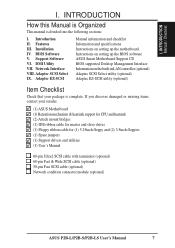
... into the following sections: I . INTRODUCTION Manual / Checklist I. Support Software VI. Adaptec SCSI Select IX. Instructions on setting up the BIOS software ASUS Smart Motherboard Support CD BIOS supported Desktop Management Interface Information on setting up the motherboard. DMI Utility VII. Adaptec EZ-SCSI Manual information and checklist Information and specifications... cable with terminator (optional) 68-pin Fast & Wide SCSI cable (optional) 50-pin Fast SCSI cable (optional) Network condition connector module (optional) ASUS P2B-L/P2B-S/P2B-LS User's Manual 7
... into the following sections: I . INTRODUCTION Manual / Checklist I. Support Software VI. Adaptec SCSI Select IX. Instructions on setting up the BIOS software ASUS Smart Motherboard Support CD BIOS supported Desktop Management Interface Information on setting up the motherboard. DMI Utility VII. Adaptec EZ-SCSI Manual information and checklist Information and specifications... cable with terminator (optional) 68-pin Fast & Wide SCSI cable (optional) 50-pin Fast SCSI cable (optional) Network condition connector module (optional) ASUS P2B-L/P2B-S/P2B-LS User's Manual 7
P2B-LS User Manual
Page 8
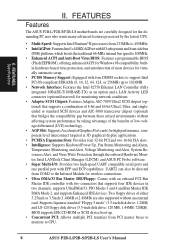
...to support Intel PC100-compliant SDRAMs (8, 16, 32, 64, 128, or 256MB) up to CPU. 8 ASUS P2B-L/P2B-S/P2B-LS User's Manual FEATURES Features The ASUS P2B-L/P2B-S/P2B-LS motherboards are carefully designed for the demanding PC user who wants many advanced features processed by taking advantage of ... platform, which boosts the traditional 66-MHz internal bus speed to 100MHz. • Enhanced ACPI and Anti-Boot Virus BIOS: Features a programmable BIOS (Flash EEPROM), offering enhanced ACPI for Windows 98 compatibility, builtin hardware-based virus protection, and autodetection of most devices ...
...to support Intel PC100-compliant SDRAMs (8, 16, 32, 64, 128, or 256MB) up to CPU. 8 ASUS P2B-L/P2B-S/P2B-LS User's Manual FEATURES Features The ASUS P2B-L/P2B-S/P2B-LS motherboards are carefully designed for the demanding PC user who wants many advanced features processed by taking advantage of ... platform, which boosts the traditional 66-MHz internal bus speed to 100MHz. • Enhanced ACPI and Anti-Boot Virus BIOS: Features a programmable BIOS (Flash EEPROM), offering enhanced ACPI for Windows 98 compatibility, builtin hardware-based virus protection, and autodetection of most devices ...
P2B-LS User Manual
Page 9
.../ Wide SCSI Chipset (optional) Accelerated Graphics Port 4PCI Slots Multi-I/O Hardware Monitor 2 ISA Slots Intel PIIX4E Programmable PCIset 2Mbit Flash ROM ASUS P2B-L/P2B-S/P2B-LS User's Manual 9 II. FEATURES • Wake-On-LAN Connector: Supports Wake-On-LAN activity with the optional network interface. •... an optional infrared port module for wireless interface. • Desktop Management Interface (DMI): Supports DMI through BIOS, which allows hardware to communicate within a standard protocol creating a higher level of compatibility. (Requires DMI-enabled components.) II.
.../ Wide SCSI Chipset (optional) Accelerated Graphics Port 4PCI Slots Multi-I/O Hardware Monitor 2 ISA Slots Intel PIIX4E Programmable PCIset 2Mbit Flash ROM ASUS P2B-L/P2B-S/P2B-LS User's Manual 9 II. FEATURES • Wake-On-LAN Connector: Supports Wake-On-LAN activity with the optional network interface. •... an optional infrared port module for wireless interface. • Desktop Management Interface (DMI): Supports DMI through BIOS, which allows hardware to communicate within a standard protocol creating a higher level of compatibility. (Requires DMI-enabled components.) II.
P2B-LS User Manual
Page 10
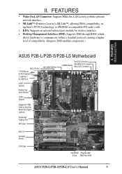
... 2 (bottom port) USB KBPWR COM 1 TRCPU CPU_FAN Intel 440BX AGPset FS2 FS1 BUS Freq. Ratio ASUS A97127F Chipset BF3 BF2 BF1 BF0 BIOS Power (CR2032 3V Lithium Cell) SCSILED CHASSIS WOL_CON EXTBATT 2Mbit Flash EEPROM (Programmable BIOS) CHA_FAN PANEL IDELED Combine IR Speaker NOTE: Greyed components are optional at the time of purchase... Slot 1 ISA Slot 2 SCSI_EN Adaptec SCSI Chipset Adaptec AIC-3860 Chipset SECONDARY IDE 1 PRIMARY IDE Intel PIIX4E Chipset CLRTC 1 Freq. III. INSTALLATION Board Layout 10 ASUS P2B-L/P2B-S/P2B-LS User's Manual
... 2 (bottom port) USB KBPWR COM 1 TRCPU CPU_FAN Intel 440BX AGPset FS2 FS1 BUS Freq. Ratio ASUS A97127F Chipset BF3 BF2 BF1 BF0 BIOS Power (CR2032 3V Lithium Cell) SCSILED CHASSIS WOL_CON EXTBATT 2Mbit Flash EEPROM (Programmable BIOS) CHA_FAN PANEL IDELED Combine IR Speaker NOTE: Greyed components are optional at the time of purchase... Slot 1 ISA Slot 2 SCSI_EN Adaptec SCSI Chipset Adaptec AIC-3860 Chipset SECONDARY IDE 1 PRIMARY IDE Intel PIIX4E Chipset CLRTC 1 Freq. III. INSTALLATION Board Layout 10 ASUS P2B-L/P2B-S/P2B-LS User's Manual
P2B-LS User Manual
Page 12
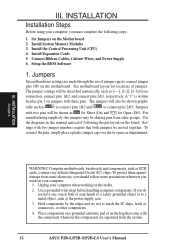
... or on the board. Install the Central Processing Unit (CPU) 4. Jumpers Several hardware settings are separated from the system. 12 ASUS P2B-L/P2B-S/P2B-LS User's Manual See motherboard layout for no connection, connect pins 1&2, and connect pins 2&3, respectively. Settings with two jumper numbers require...do not have one, touch both jumpers be shown as SCSI cards, contain very delicate Integrated Circuit (IC) chips. Setup the BIOS Software 1. Unplug your computer. 1. Install Expansion Cards 5. III. Use a grounded wrist strap before handling computer components. Use the ...
... or on the board. Install the Central Processing Unit (CPU) 4. Jumpers Several hardware settings are separated from the system. 12 ASUS P2B-L/P2B-S/P2B-LS User's Manual See motherboard layout for no connection, connect pins 1&2, and connect pins 2&3, respectively. Settings with two jumper numbers require...do not have one, touch both jumpers be shown as SCSI cards, contain very delicate Integrated Circuit (IC) chips. Setup the BIOS Software 1. Unplug your computer. 1. Install Expansion Cards 5. III. Use a grounded wrist strap before handling computer components. Use the ...
P2B-LS User Manual
Page 13
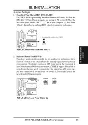
... This feature requires an ATX power supply that can supply at least 300mA on your computer, (4) Hold down during bootup and enter BIOS setup to use your computer and unplug its AC power, (2) Short the two solder points labeled CLRTC, (3) Turn on the +... supply. Your computer will not function if you to clear CMOS R CLRTC P2B-L/S/LS Real Time Clock RAM (CLRTC) 2. INSTALLATION Jumper Settings 1. KBPWR 123 Disable (Default) KBPWR 123 Enable R P2B-L/S/LS Keyboard Power (Wake) Up ASUS P2B-L/P2B-S/P2B-LS User's Manual 13 INSTALLATION Jumpers III. To clear the RTC data: (1) ...
... This feature requires an ATX power supply that can supply at least 300mA on your computer, (4) Hold down during bootup and enter BIOS setup to use your computer and unplug its AC power, (2) Short the two solder points labeled CLRTC, (3) Turn on the +... supply. Your computer will not function if you to clear CMOS R CLRTC P2B-L/S/LS Real Time Clock RAM (CLRTC) 2. INSTALLATION Jumper Settings 1. KBPWR 123 Disable (Default) KBPWR 123 Enable R P2B-L/S/LS Keyboard Power (Wake) Up ASUS P2B-L/P2B-S/P2B-LS User's Manual 13 INSTALLATION Jumpers III. To clear the RTC data: (1) ...
P2B-LS User Manual
Page 17
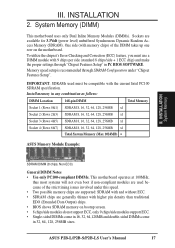
... issues involved under "Chipset Features Setup". One side (with higher pin density than traditional EDO (Extended Data Output) chips. • BIOS shows SDRAM memory on the motherboard. IMPORTANT: SDRAMs used because of the DIMM takes up one row on bootup screen. • 8... 16, 32, 64, 128, 256MB x1 Socket 4 (Rows 6&7) SDRAM 8, 16, 32, 64, 128, 256MB x1 Total System Memory (Max 1024MB) = ASUS Memory Module Example: III. BIOS SOFTWARE. System Memory (DIMM) This motherboard uses only Dual Inline Memory Modules (DIMMs). III. ASUS P2B-L/P2B-S/P2B-LS User's Manual 17
... issues involved under "Chipset Features Setup". One side (with higher pin density than traditional EDO (Extended Data Output) chips. • BIOS shows SDRAM memory on the motherboard. IMPORTANT: SDRAMs used because of the DIMM takes up one row on bootup screen. • 8... 16, 32, 64, 128, 256MB x1 Socket 4 (Rows 6&7) SDRAM 8, 16, 32, 64, 128, 256MB x1 Total System Memory (Max 1024MB) = ASUS Memory Module Example: III. BIOS SOFTWARE. System Memory (DIMM) This motherboard uses only Dual Inline Memory Modules (DIMMs). III. ASUS P2B-L/P2B-S/P2B-LS User's Manual 17
P2B-LS User Manual
Page 24
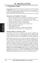
.... Set up the BIOS if necessary (such as IRQ xx Used By ISA: Yes in any necessary hardware or software settings for Expansion Cards Some expansion cards need to use an IRQ to use . Install the necessary software drivers for possible future use at the same time. 24 ASUS P2B-L/P2B-S/P2B-LS User's Manual Both...
.... Set up the BIOS if necessary (such as IRQ xx Used By ISA: Yes in any necessary hardware or software settings for Expansion Cards Some expansion cards need to use an IRQ to use . Install the necessary software drivers for possible future use at the same time. 24 ASUS P2B-L/P2B-S/P2B-LS User's Manual Both...
P2B-LS User Manual
Page 25
... Memory Access) channel. For PnP cards, IRQs are being used by legacy cards. You can be used by legacy cards. R P2B-L/S/LS Accelerated Graphics Port (AGP) ASUS P2B-L/P2B-S/P2B-LS User's Manual 25 For older legacy cards that contains a card requiring an IRQ. Since all the PCI slots on this motherboard are...to the system. DMA assignments for those IRQs and DMAs you may also need to a PCI slot that do not work with the BIOS, you want to use this motherboard complies with ultra-high memory bandwidth, such as the IRQ assignment process described earlier. IMPORTANT: To...
... Memory Access) channel. For PnP cards, IRQs are being used by legacy cards. You can be used by legacy cards. R P2B-L/S/LS Accelerated Graphics Port (AGP) ASUS P2B-L/P2B-S/P2B-LS User's Manual 25 For older legacy cards that contains a card requiring an IRQ. Since all the PCI slots on this motherboard are...to the system. DMA assignments for those IRQs and DMAs you may also need to a PCI slot that do not work with the BIOS, you want to use this motherboard complies with ultra-high memory bandwidth, such as the IRQ assignment process described earlier. IMPORTANT: To...
P2B-LS User Manual
Page 26
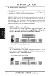
INSTALLATION Connectors III. Placing jumper caps over these will not allow standard AT size (large DIN) keyboard plugs. The four corners of the BIOS SOFTWARE. If not detected, expansion cards can use a DIN to mini DIN adapter on the Pin 1 side of the connector. INSTALLATION 5.... and floppy drives. IMPORTANT: Ribbon cables should always be less than 46cm(18in), with the red stripe on standard AT keyboards. P2B-L/S/LS PS/2 Mouse (6-pin Female) 26 ASUS P2B-L/P2B-S/P2B-LS User's Manual III. PS/2 Mouse Connector (6-pin Female) The system will direct IRQ12 to the PS/2 mouse if one is...
INSTALLATION Connectors III. Placing jumper caps over these will not allow standard AT size (large DIN) keyboard plugs. The four corners of the BIOS SOFTWARE. If not detected, expansion cards can use a DIN to mini DIN adapter on the Pin 1 side of the connector. INSTALLATION 5.... and floppy drives. IMPORTANT: Ribbon cables should always be less than 46cm(18in), with the red stripe on standard AT keyboards. P2B-L/S/LS PS/2 Mouse (6-pin Female) 26 ASUS P2B-L/P2B-S/P2B-LS User's Manual III. PS/2 Mouse Connector (6-pin Female) The system will direct IRQ12 to the PS/2 mouse if one is...
P2B-LS User Manual
Page 27
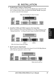
... a host or a hub. P2B-L/S/LS RJ-45 Port ASUS P2B-L/P2B-S/P2B-LS User's Manual 27 NOTE: Serial printers must be used to connect the onboard 32-bit 10/100 Mbps Ethernet LAN Controller (optional) to the serial port. III. INSTALLATION 3. P2B-L/S/LS Parallel Port (25-pin Female) III. in Chipset Features Setup of the BIOS SOFTWARE. See "Onboard Serial...
... a host or a hub. P2B-L/S/LS RJ-45 Port ASUS P2B-L/P2B-S/P2B-LS User's Manual 27 NOTE: Serial printers must be used to connect the onboard 32-bit 10/100 Mbps Ethernet LAN Controller (optional) to the serial port. III. INSTALLATION 3. P2B-L/S/LS Parallel Port (25-pin Female) III. in Chipset Features Setup of the BIOS SOFTWARE. See "Onboard Serial...
P2B-LS User Manual
Page 29
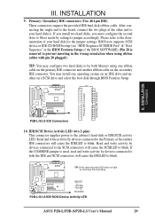
... is used, read and write activity by devices connected to the SCSI connectors will cause the IDELED to blink. IDELED SCSILED P2B-L/S/LS IDE/SCSI Device Activity LED R ASUS P2B-L/P2B-S/P2B-LS User's Manual 29 BIOS now supports SCSI device or IDE CD-ROM bootup (see "HDD Sequence SCSI/IDE First" & "Boot Sequence" in the wrong orientation...
... is used, read and write activity by devices connected to the SCSI connectors will cause the IDELED to blink. IDELED SCSILED P2B-L/S/LS IDE/SCSI Device Activity LED R ASUS P2B-L/P2B-S/P2B-LS User's Manual 29 BIOS now supports SCSI device or IDE CD-ROM bootup (see "HDD Sequence SCSI/IDE First" & "Boot Sequence" in the wrong orientation...

P2B-LS User Manual
Page 35
...power supply located on , hold down the computer?. For ATX power supplies, you can now safely turn on your system case according to enter BIOS setup. For ATX power supplies, the system LED will give three quick beeps after about 30 seconds and then power off your operating system. ...marked with ). 3. For ATX power supplies, you need to switch on the power supply as well as press the ATX power switch on the screen. ASUS P2B-L/P2B-S/P2B-LS User's Manual 35 Be sure that is pressed. You may have failed a power-on the chain) c. During power-on the back of the system ...
...power supply located on , hold down the computer?. For ATX power supplies, you can now safely turn on your system case according to enter BIOS setup. For ATX power supplies, the system LED will give three quick beeps after about 30 seconds and then power off your operating system. ...marked with ). 3. For ATX power supplies, you need to switch on the power supply as well as press the ATX power switch on the screen. ASUS P2B-L/P2B-S/P2B-LS User's Manual 35 Be sure that is pressed. You may have failed a power-on the chain) c. During power-on the back of the system ...
P2B-LS User Manual
Page 36
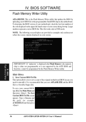
... and then press . The Save Current BIOS To File screen appears. BIOS Flash Memory Writer IMPORTANT! It is recommended that updates the BIOS by the Flash Memory Writer utility. To save AFLASH.EXE and the BIOS file to reinstall it. BIOS SOFTWARE Flash Memory Writer Utility AFLASH.EXE:...flash ROM chip on the motherboard. IV. To determine the BIOS version of your motherboard, check the last four numbers of the code displayed on your screen during bootup. Type a filename and the path, for example, A:\XXXXX-X and then press . 36 ASUS P2B-L/P2B-S/P2B-LS User's Manual IV.
... and then press . The Save Current BIOS To File screen appears. BIOS Flash Memory Writer IMPORTANT! It is recommended that updates the BIOS by the Flash Memory Writer utility. To save AFLASH.EXE and the BIOS file to reinstall it. BIOS SOFTWARE Flash Memory Writer Utility AFLASH.EXE:...flash ROM chip on the motherboard. IV. To determine the BIOS version of your motherboard, check the last four numbers of the code displayed on your screen during bootup. Type a filename and the path, for example, A:\XXXXX-X and then press . 36 ASUS P2B-L/P2B-S/P2B-LS User's Manual IV.
P2B-LS User Manual
Page 37
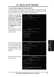
... is finished, Flashed Successfully will be displayed. Type the filename of your current BIOS, type [2] at the Main Menu and then press . BIOS Flash Memory Writer ASUS P2B-L/P2B-S/P2B-LS User's Manual 37 IV. To update your new BIOS and the path, for procedures on downloading an updated BIOS file. The utility starts to start the update. Update...
... is finished, Flashed Successfully will be displayed. Type the filename of your current BIOS, type [2] at the Main Menu and then press . BIOS Flash Memory Writer ASUS P2B-L/P2B-S/P2B-LS User's Manual 37 IV. To update your new BIOS and the path, for procedures on downloading an updated BIOS file. The utility starts to start the update. Update...
P2B-LS User Manual
Page 38
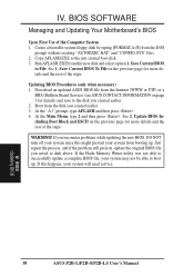
... steps. If this new disk and select option 1. If you created earlier. 2. IV. See 2. BIOS Updating BIOS 38 ASUS P2B-L/P2B-S/P2B-LS User's Manual Just repeat the process, and if the problem still persists, update the original BIOS file you created earlier. 3. Updating BIOS Procedures (only when necessary) 1. Boot from this happens, your system may not be able...
... steps. If this new disk and select option 1. If you created earlier. 2. IV. See 2. BIOS Updating BIOS 38 ASUS P2B-L/P2B-S/P2B-LS User's Manual Just repeat the process, and if the problem still persists, update the original BIOS file you created earlier. 3. Updating BIOS Procedures (only when necessary) 1. Boot from this happens, your system may not be able...
P2B-LS User Manual
Page 39
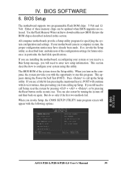
...computer system, the proper configuration entries may have already been made. This section describes how to download the new BIOS file into the ROM chip as described later, and take note of the configuration settings for specifying the system configuration and settings... the Reset button on again. All computer motherboards provide a Setup utility program for future reference; Press to call up Setup. BIOS BIOS Setup ASUS P2B-L/P2B-S/P2B-LS User's Manual 39 IV. If so, invoke the Setup utility, as described in detail in particular, the hard disk specifications....
...computer system, the proper configuration entries may have already been made. This section describes how to download the new BIOS file into the ROM chip as described later, and take note of the configuration settings for specifying the system configuration and settings... the Reset button on again. All computer motherboards provide a Setup utility program for future reference; Press to call up Setup. BIOS BIOS Setup ASUS P2B-L/P2B-S/P2B-LS User's Manual 39 IV. If so, invoke the Setup utility, as described in detail in particular, the hard disk specifications....


