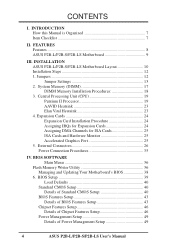
P2B-L User Manual
Page 4
... ASUS P2B-L/P2B-S/P2B-LS Motherboard Layout... 10 Installation Steps 12 1. BIOS Setup 39 Load Defaults 40 Standard CMOS Setup 40 Details of Standard CMOS Setup 40 BIOS Features Setup 43 Details of BIOS Features Setup 43 Chipset Features Setup 46 Details of Chipset Features Setup 46 Power Management Setup 49 Details of Power Management Setup 49 4 ASUS P2B-L/P2B-S/P2B...25 5. System Memory (DIMM 17 DIMM Memory Installation Procedures 18 3. FEATURES Features 8 ASUS P2B-L/P2B-S/P2B-LS Motherboard 9 III. Central Processing Unit (CPU 19 Pentium II Processor 19 AAVID...
... ASUS P2B-L/P2B-S/P2B-LS Motherboard Layout... 10 Installation Steps 12 1. BIOS Setup 39 Load Defaults 40 Standard CMOS Setup 40 Details of Standard CMOS Setup 40 BIOS Features Setup 43 Details of BIOS Features Setup 43 Chipset Features Setup 46 Details of Chipset Features Setup 46 Power Management Setup 49 Details of Power Management Setup 49 4 ASUS P2B-L/P2B-S/P2B...25 5. System Memory (DIMM 17 DIMM Memory Installation Procedures 18 3. FEATURES Features 8 ASUS P2B-L/P2B-S/P2B-LS Motherboard 9 III. Central Processing Unit (CPU 19 Pentium II Processor 19 AAVID...
P2B-L User Manual
Page 10
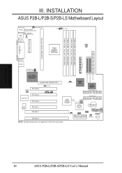
...EXTBATT 2Mbit Flash EEPROM (Programmable BIOS) CHA_FAN PANEL IDELED Combine IR Speaker NOTE: Greyed components are optional at the time of purchase. INSTALLATION ASUS P2B-L/P2B-S/P2B-LS Motherboard Layout DIMM Socket 0 (64/72 bit, 168 pin module) DIMM Socket 1 (64/72 bit, 168 pin module) DIMM Socket 2 (...port) USB 1 (top port) USB 2 (bottom port) USB KBPWR COM 1 TRCPU CPU_FAN Intel 440BX AGPset FS2 FS1 BUS Freq. INSTALLATION Board Layout 10 ASUS P2B-L/P2B-S/P2B-LS User's Manual FS0 68 34 34 68 COM 2 RJ-45 1 FLOPPY LAN Activity LED Connector 35 1 35 1 50-Pin SCSI 1 ...
...EXTBATT 2Mbit Flash EEPROM (Programmable BIOS) CHA_FAN PANEL IDELED Combine IR Speaker NOTE: Greyed components are optional at the time of purchase. INSTALLATION ASUS P2B-L/P2B-S/P2B-LS Motherboard Layout DIMM Socket 0 (64/72 bit, 168 pin module) DIMM Socket 1 (64/72 bit, 168 pin module) DIMM Socket 2 (...port) USB 1 (top port) USB 2 (bottom port) USB KBPWR COM 1 TRCPU CPU_FAN Intel 440BX AGPset FS2 FS1 BUS Freq. INSTALLATION Board Layout 10 ASUS P2B-L/P2B-S/P2B-LS User's Manual FS0 68 34 34 68 COM 2 RJ-45 1 FLOPPY LAN Activity LED Connector 35 1 35 1 50-Pin SCSI 1 ...
P2B-L User Manual
Page 11
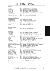
ASUS P2B-L/P2B-S/P2B-LS User's Manual 11 INSTALLATION Jumpers 1) CLRTC 2) KBPWR 3) LAN_EN 4) SCSI_EN 5) COMBINE 6) FS0, FS1, FS2 7) BF0, BF1, BF2, BF3 p. 13 Clear Real Time Clock (RTC) RAM p. ...) *The onboard hardware monitor uses the address 290H-297H so legacy ISA cards must not use this address, otherwise conflicts will occur. III. INSTALLATION Board Layout III.
ASUS P2B-L/P2B-S/P2B-LS User's Manual 11 INSTALLATION Jumpers 1) CLRTC 2) KBPWR 3) LAN_EN 4) SCSI_EN 5) COMBINE 6) FS0, FS1, FS2 7) BF0, BF1, BF2, BF3 p. 13 Clear Real Time Clock (RTC) RAM p. ...) *The onboard hardware monitor uses the address 290H-297H so legacy ISA cards must not use this address, otherwise conflicts will occur. III. INSTALLATION Board Layout III.

P2B-L User Manual
Page 12
... the Central Processing Unit (CPU) 4. Setup the BIOS Software 1. The jumpers will be sharing pins from the system. 12 ASUS P2B-L/P2B-S/P2B-LS User's Manual III. To protect them against damage from static electricity, you should follow some precautions whenever you work on the...the Motherboard 2. cally such as the power supply case. 3. Settings with two pins will also be moved together. See motherboard layout for no connection, connect pins 1&2, and connect pins 2&3, respectively. INSTALLATION Installation Steps Before using your hands to a safely grounded ...
... the Central Processing Unit (CPU) 4. Setup the BIOS Software 1. The jumpers will be sharing pins from the system. 12 ASUS P2B-L/P2B-S/P2B-LS User's Manual III. To protect them against damage from static electricity, you should follow some precautions whenever you work on the...the Motherboard 2. cally such as the power supply case. 3. Settings with two pins will also be moved together. See motherboard layout for no connection, connect pins 1&2, and connect pins 2&3, respectively. INSTALLATION Installation Steps Before using your hands to a safely grounded ...

P2B-L User Manual
Page 20
... installed. Do not overtighten the captive nuts. Tighten captive nuts to align the notch in place. Lock holes Captive nut Captive nut 20 ASUS P2B-L/P2B-S/P2B-LS User's Manual WARNING! INSTALLATION Attach Mount Bridges Four screws should be showing next to fit into the SEC slot only one side of...slot and that the mechanism is properly seated on one way. TIP: Orient the mechanism's lock holes toward the motherboard's chipset (see motherboard layout for the location of the SEC CPU Slot with the small rib on the board. SEC CPU slot NOTE: Encircled items are the screws ...
... installed. Do not overtighten the captive nuts. Tighten captive nuts to align the notch in place. Lock holes Captive nut Captive nut 20 ASUS P2B-L/P2B-S/P2B-LS User's Manual WARNING! INSTALLATION Attach Mount Bridges Four screws should be showing next to fit into the SEC slot only one side of...slot and that the mechanism is properly seated on one way. TIP: Orient the mechanism's lock holes toward the motherboard's chipset (see motherboard layout for the location of the SEC CPU Slot with the small rib on the board. SEC CPU slot NOTE: Encircled items are the screws ...

P2B-L User Manual
Page 64
... RJ45 Connector Pin 1 Pin 2 Pin 3 Pin 6 Pins 4,5,7,8 Output Transmit Data + Output Transmit Data Input Receive Data + Input Receive Data (Reserved) HUB RJ45 Connector 12345678 64 ASUS P2B-L/P2B-S/P2B-LS User's Manual Connect a single network cable to monitor connection speed. The rate of network traffic. If Off, the network connection is proportional to a 100Base...-TX host. The end connectors are called a straight-through the RJ45 port. Speed Indicator: This connects to an LED to the RJ45 connector. NETWORK Layout/Installation VII.
... RJ45 Connector Pin 1 Pin 2 Pin 3 Pin 6 Pins 4,5,7,8 Output Transmit Data + Output Transmit Data Input Receive Data + Input Receive Data (Reserved) HUB RJ45 Connector 12345678 64 ASUS P2B-L/P2B-S/P2B-LS User's Manual Connect a single network cable to monitor connection speed. The rate of network traffic. If Off, the network connection is proportional to a 100Base...-TX host. The end connectors are called a straight-through the RJ45 port. Speed Indicator: This connects to an LED to the RJ45 connector. NETWORK Layout/Installation VII.

