User Manual
Page 1
R P/I-P55T2P4 Pentium® Motherboard USER'S MANUAL
R P/I-P55T2P4 Pentium® Motherboard USER'S MANUAL

User Manual
Page 2
... to the implied warranties or conditions of merchantability or fitness for indirect, special, incidental, or consequential damages of any kind, even if ASUS has been advised of the possibility of such damages arising from time to time without warranty of any loss or profits, loss of business... on top left during boot-up) Release Date: April 1996 II P/I-P55T2P4 User's Manual All rights reserved. In no event shall ASUS be liable for any kind, either express or implied, including but not limited to as is" without notice. ASUS provides this manual are mentioned for backup purposes.
... to the implied warranties or conditions of merchantability or fitness for indirect, special, incidental, or consequential damages of any kind, even if ASUS has been advised of the possibility of such damages arising from time to time without warranty of any loss or profits, loss of business... on top left during boot-up) Release Date: April 1996 II P/I-P55T2P4 User's Manual All rights reserved. In no event shall ASUS be liable for any kind, either express or implied, including but not limited to as is" without notice. ASUS provides this manual are mentioned for backup purposes.
User Manual
Page 4
...Memory (DRAM & SRAM 12 DRAM Memory Installation Procedures 13 Level 2 External Static RAM (SRAM) Cache 14 Compatible Cache Modules for ISA Cards 17 ASUS MediaBus Card 18 5. INSTALLATION 4 Map of the Motherboard 3 III. Jumpers 6 Jumper Settings 8 2. INTRODUCTION 1 How this Motherboard 14 3. External...for Expansion Cards 16 Assigning DMA Channels for this manual is organized 1 Item Checklist 1 II. CONTENTS I -P55T2P4 User's Manual FEATURES 2 Features of This Motherboard 2 Parts of the Motherboard 4 Jumpers 5 Expansion Slots 5 Connectors 5 Installation Steps 6 1.
...Memory (DRAM & SRAM 12 DRAM Memory Installation Procedures 13 Level 2 External Static RAM (SRAM) Cache 14 Compatible Cache Modules for ISA Cards 17 ASUS MediaBus Card 18 5. INSTALLATION 4 Map of the Motherboard 3 III. Jumpers 6 Jumper Settings 8 2. INTRODUCTION 1 How this Motherboard 14 3. External...for Expansion Cards 16 Assigning DMA Channels for this manual is organized 1 Item Checklist 1 II. CONTENTS I -P55T2P4 User's Manual FEATURES 2 Features of This Motherboard 2 Parts of the Motherboard 4 Jumpers 5 Expansion Slots 5 Connectors 5 Installation Steps 6 1.
User Manual
Page 5
... The PCI-SC200 SCSI Interface Card 52 Setting Up the PCI-SC200 52 Setting the INT Assignment 53 Terminator Settings 53 SCSI ID Numbers 54 P/I-P55T2P4 User's Manual V BIOS SOFTWARE 26 6. CONTENTS IV.
... The PCI-SC200 SCSI Interface Card 52 Setting Up the PCI-SC200 52 Setting the INT Assignment 53 Terminator Settings 53 SCSI ID Numbers 54 P/I-P55T2P4 User's Manual V BIOS SOFTWARE 26 6. CONTENTS IV.
User Manual
Page 6
... is required to the graphics card is no guarantee that may cause undesired operation. This equipment has been tested and found to this equipment. VI P/I-P55T2P4 User's Manual Changes or modifications to comply with the limits for help.
... is required to the graphics card is no guarantee that may cause undesired operation. This equipment has been tested and found to this equipment. VI P/I-P55T2P4 User's Manual Changes or modifications to comply with the limits for help.
User Manual
Page 7
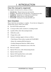
...1 floppy ribbon cable √ 1 diskette containing support software as follows: 1. Item Checklist Please check that your retailer. √ The P/I-P55T2P4 motherboard √ 2 serial port ribbon cables attached to update the FLASH BIOS • Binary file containing BIOS information • Desktop Management ...Writer utility to a mounting bracket √ 1 parallel ribbon cable with mounting bracket Optional infrared module Optional ASUS pipelined burst cache module Optional PCI-SC200 SCSI card P/I . Features: Information and specifications concerning this manual is organized This ...
...1 floppy ribbon cable √ 1 diskette containing support software as follows: 1. Item Checklist Please check that your retailer. √ The P/I-P55T2P4 motherboard √ 2 serial port ribbon cables attached to update the FLASH BIOS • Binary file containing BIOS information • Desktop Management ...Writer utility to a mounting bracket √ 1 parallel ribbon cable with mounting bracket Optional infrared module Optional ASUS pipelined burst cache module Optional PCI-SC200 SCSI card P/I . Features: Information and specifications concerning this manual is organized This ...
User Manual
Page 8
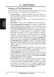
... supports auto detection of compatibility. (Requires DMI-enabled components. Two floppy drives of either an standard PCI card or the ASUS MediaBus Card. • ASUS MediaBus Rev 2.0: Features an expansion slot extension shared with I/O subsystems. • Error Checking and Correcting (ECC): Using... -board 512KB Pipelined Burst SRAM. FEATURES (Features) II. The Japanese "Floppy 3 mode" (3.5" 1.2MB) floppy standard is also supported. 2 P/I -P55T2P4 is carefully designed for details.) • L2 Cache: Provides the option of either 5.25" or 3.5" (1.44MB or 2.88MB) are made through a...
... supports auto detection of compatibility. (Requires DMI-enabled components. Two floppy drives of either an standard PCI card or the ASUS MediaBus Card. • ASUS MediaBus Rev 2.0: Features an expansion slot extension shared with I/O subsystems. • Error Checking and Correcting (ECC): Using... -board 512KB Pipelined Burst SRAM. FEATURES (Features) II. The Japanese "Floppy 3 mode" (3.5" 1.2MB) floppy standard is also supported. 2 P/I -P55T2P4 is carefully designed for details.) • L2 Cache: Provides the option of either 5.25" or 3.5" (1.44MB or 2.88MB) are made through a...
User Manual
Page 9
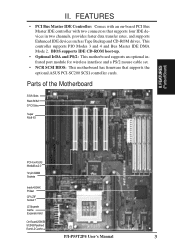
... such as Tape Backup and CD-ROM drives. Parts of the Motherboard 3 ISA Slots Flash ROM 3 PCI Slots Super Multi-I/O PCI 4 or ASUS MediaBus 2.0 72-pin SIMM Sockets Intel's 430HX PCIset CPU ZIF Socket 7 L2 Upgrade Cache Expansion Slot On-Board 256KB/ 512KB Pipelined Burst L2 Cache... P/I-P55T2P4 User's Manual 3 II. FEATURES (PartsofBoard) II. FEATURES • PCI Bus Master IDE Controller: Comes with an on-board PCI Bus Master IDE controller...
... such as Tape Backup and CD-ROM drives. Parts of the Motherboard 3 ISA Slots Flash ROM 3 PCI Slots Super Multi-I/O PCI 4 or ASUS MediaBus 2.0 72-pin SIMM Sockets Intel's 430HX PCIset CPU ZIF Socket 7 L2 Upgrade Cache Expansion Slot On-Board 256KB/ 512KB Pipelined Burst L2 Cache... P/I-P55T2P4 User's Manual 3 II. FEATURES (PartsofBoard) II. FEATURES • PCI Bus Master IDE Controller: Comes with an on-board PCI Bus Master IDE controller...
User Manual
Page 10
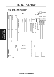
INSTALLATION FOR SMC 37C669 SIMM Slot 4 SIMM Slot 3 SIMM Slot 2 SIMM Slot 1 Board Power Input JP1 Secondary IDE MULTI I/O UMC OR SMC Primary IDE PCI Slot 1 Floppy Drives PCI Slot 2 PCI Slot 3 PCI Slot 4 / MediaBus 2.0 ISA Slot 1 ISA Slot 2 ISA Slot 3 JP19 JP13 Fan Power Pipelined Burst Level 2 Cache Expansion Slot ZIF Socket 7 JP11 JP12 JP9 JP10 JP20 I -P55T2P4 User's Manual Map of Board) INSTALLATION (Map of the Motherboard JP8 JP18 III. JP2 256KB On-Board L2 Cache Parallel Printer COM 1 COM 2 Keyboard PS/2 Mouse P/I R IDE LED JP17 CON1 4 III.
INSTALLATION FOR SMC 37C669 SIMM Slot 4 SIMM Slot 3 SIMM Slot 2 SIMM Slot 1 Board Power Input JP1 Secondary IDE MULTI I/O UMC OR SMC Primary IDE PCI Slot 1 Floppy Drives PCI Slot 2 PCI Slot 3 PCI Slot 4 / MediaBus 2.0 ISA Slot 1 ISA Slot 2 ISA Slot 3 JP19 JP13 Fan Power Pipelined Burst Level 2 Cache Expansion Slot ZIF Socket 7 JP11 JP12 JP9 JP10 JP20 I -P55T2P4 User's Manual Map of Board) INSTALLATION (Map of the Motherboard JP8 JP18 III. JP2 256KB On-Board L2 Cache Parallel Printer COM 1 COM 2 Keyboard PS/2 Mouse P/I R IDE LED JP17 CON1 4 III.
User Manual
Page 11
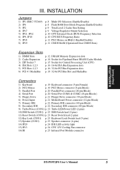
... Speaker connector (4-pins) 14) JP20 p. 24 IDE LED activity light 15) JP13 p. 24 CPU 12V Cooling Fan connector 16) IR p. 25 Infrared Port Module connector P/I-P55T2P4 User's Manual 5 III. INSTALLATION (MapofBoard) III.
... Speaker connector (4-pins) 14) JP20 p. 24 IDE LED activity light 15) JP13 p. 24 CPU 12V Cooling Fan connector 16) IR p. 25 Infrared Port Module connector P/I-P55T2P4 User's Manual 5 III. INSTALLATION (MapofBoard) III.
User Manual
Page 12
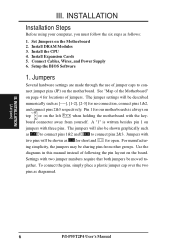
... the BIOS Software 1. Jumpers with two jumper numbers require that both jumpers be described numerically such as to connect pins 1&2 and to con- INSTALLATION (Jumpers) 6 P/I-P55T2P4 User's Manual nect jumper pins (JP) on the Motherboard 2. III. Set Jumpers on the motherboard. See "Map of the Motherboard" on page 4 for our motherboards...
... the BIOS Software 1. Jumpers with two jumper numbers require that both jumpers be described numerically such as to connect pins 1&2 and to con- INSTALLATION (Jumpers) 6 P/I-P55T2P4 User's Manual nect jumper pins (JP) on the Motherboard 2. III. Set Jumpers on the motherboard. See "Map of the Motherboard" on page 4 for our motherboards...
User Manual
Page 13
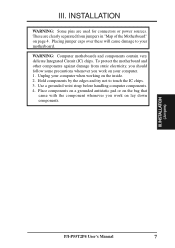
... your motherboard. Place components on a grounded antistatic pad or on the bag that came with the component whenever you work on the inside. 2. INSTALLATION (Jumpers) P/I-P55T2P4 User's Manual 7 III.
... your motherboard. Place components on a grounded antistatic pad or on the bag that came with the component whenever you work on the inside. 2. INSTALLATION (Jumpers) P/I-P55T2P4 User's Manual 7 III.
User Manual
Page 14
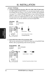
... (see page 35) or disable all Multi-I /O, the following jumper in the Enabled position. Selections Enable Disable JP1 [1-2] (Default) [2-3] JP 1 1 2 3 Enable (Default) JP 1 1 2 3 Disabled Multi I -P55T2P4 User's Manual
... (see page 35) or disable all Multi-I /O, the following jumper in the Enabled position. Selections Enable Disable JP1 [1-2] (Default) [2-3] JP 1 1 2 3 Enable (Default) JP 1 1 2 3 Disabled Multi I -P55T2P4 User's Manual
User Manual
Page 15
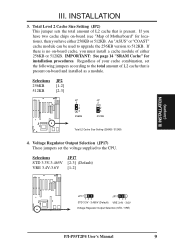
III. INSTALLATION 3. An "ASUS" or "COAST" cache module can be used to upgrade the 256KB version to the CPU. Voltage Regulator Output Selection (JP17) These jumpers set the following ..., set the voltage supplied to 512KB. INSTALLATION (Jumpers) JP17 123 STD 3.3V - 3.465V (Default) JP17 123 VRE 3.4V - 3.6V Voltage Regulator Output Selection (STD / VRE) P/I-P55T2P4 User's Manual 9 If you must install a cache module of Motherboard" for installation procedures. If there is present on -board cache, you have either 256KB or...
III. INSTALLATION 3. An "ASUS" or "COAST" cache module can be used to upgrade the 256KB version to the CPU. Voltage Regulator Output Selection (JP17) These jumpers set the following ..., set the voltage supplied to 512KB. INSTALLATION (Jumpers) JP17 123 STD 3.3V - 3.465V (Default) JP17 123 VRE 3.4V - 3.6V Voltage Regulator Output Selection (STD / VRE) P/I-P55T2P4 User's Manual 9 If you must install a cache module of Motherboard" for installation procedures. If there is present on -board cache, you have either 256KB or...
User Manual
Page 16
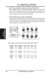
... JP11 JP10 JP9 166MHz 2.5x 66MHz [2-3] [1-2] [2-3] [2-3] 150MHz 2.5x 60MHz [1-2] [2-3] [2-3] [2-3] 133MHz 2.0x 66MHz [2-3] [1-2] [1-2] [2-3] 120MHz 2.0x 60MHz [1-2] [2-3] [1-2] [2-3] 100MHz 1.5x 66MHz 90MHz 1.5x 60MHz 75MHz 1.5x 50MHz [2-3] [1-2] [1-2] [1-2] [1-2] [2-3] [1-2] [1-2] [2-3] [2-3] [1-2] [1-2] 10 P/I-P55T2P4 User's Manual The BUS Clock times the BUS Ratio equals the CPU's Internal frequency (the advertised CPU speed). 6. JP JP 12 11 1 2 3 JP JP 12...
... JP11 JP10 JP9 166MHz 2.5x 66MHz [2-3] [1-2] [2-3] [2-3] 150MHz 2.5x 60MHz [1-2] [2-3] [2-3] [2-3] 133MHz 2.0x 66MHz [2-3] [1-2] [1-2] [2-3] 120MHz 2.0x 60MHz [1-2] [2-3] [1-2] [2-3] 100MHz 1.5x 66MHz 90MHz 1.5x 60MHz 75MHz 1.5x 50MHz [2-3] [1-2] [1-2] [1-2] [1-2] [2-3] [1-2] [1-2] [2-3] [2-3] [1-2] [1-2] 10 P/I-P55T2P4 User's Manual The BUS Clock times the BUS Ratio equals the CPU's Internal frequency (the advertised CPU speed). 6. JP JP 12 11 1 2 3 JP JP 12...
User Manual
Page 17
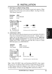
... BQ3287A chips require that your computer is done to re-enter BIOS information (see BIOS SETUP). You must enter the BIOS setup (by holding down ) P/I-P55T2P4 User's Manual 11 INSTALLATION 7. When Enabled, the port becomes active and uses IRQ12. Simply connect a jumper cap over this is turned off , (4) Open Jumper, (5) Power...
... BQ3287A chips require that your computer is done to re-enter BIOS information (see BIOS SETUP). You must enter the BIOS setup (by holding down ) P/I-P55T2P4 User's Manual 11 INSTALLATION 7. When Enabled, the port becomes active and uses IRQ12. Simply connect a jumper cap over this is turned off , (4) Open Jumper, (5) Power...
User Manual
Page 18
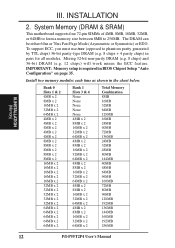
... 24MB 40MB 72MB 136MB 24MB 32MB 48MB 80MB 144MB 40MB 48MB 64MB 96MB 160MB 72MB 80MB 96MB 128MB 192MB 136MB 144MB 160MB 192MB 256MB 12 P/I-P55T2P4 User's Manual Mixing 32-bit non-parity DRAM (e.g. 8 chips) and 36-bit DRAM (e.g. 12 chips) will work minus the ECC feature. III. INSTALLATION 2. System Memory...
... 24MB 40MB 72MB 136MB 24MB 32MB 48MB 80MB 144MB 40MB 48MB 64MB 96MB 160MB 72MB 80MB 96MB 128MB 192MB 136MB 144MB 160MB 192MB 256MB 12 P/I-P55T2P4 User's Manual Mixing 32-bit non-parity DRAM (e.g. 8 chips) and 36-bit DRAM (e.g. 12 chips) will work minus the ECC feature. III. INSTALLATION 2. System Memory...

User Manual
Page 19
... side. 5. IMPORTANT: Do not use SIMM Modules that use memory modules with more than 24 chips per module. Press the memory module firmly into place. P/I-P55T2P4 User's Manual 13 Modules with the slot. 3.
... side. 5. IMPORTANT: Do not use SIMM Modules that use memory modules with more than 24 chips per module. Press the memory module firmly into place. P/I-P55T2P4 User's Manual 13 Modules with the slot. 3.
User Manual
Page 20
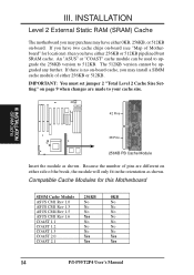
If there is no on -board. Because the number of Motherboard" for this Motherboard SIMM Cache Module 256KB 0KB ASUS CM1 Rev 1.0 No No ASUS CM1 Rev 1.3 No No ASUS CM4 Rev 1.5 No No ASUS CM1 Rev 1.6 Yes No COAST 1.1 No No COAST 1.2 No No COAST 1.3 No No COAST 2.0 Yes Yes ...COAST 2.1 Yes Yes 14 P/I-P55T2P4 User's Manual An "ASUS" or "COAST" cache module can be upgraded any further. Compatible Cache Modules for locations), then you have either 0KB, 256KB, or 512KB ...
If there is no on -board. Because the number of Motherboard" for this Motherboard SIMM Cache Module 256KB 0KB ASUS CM1 Rev 1.0 No No ASUS CM1 Rev 1.3 No No ASUS CM4 Rev 1.5 No No ASUS CM1 Rev 1.6 Yes No COAST 1.1 No No COAST 1.2 No No COAST 1.3 No No COAST 2.0 Yes Yes ...COAST 2.1 Yes Yes 14 P/I-P55T2P4 User's Manual An "ASUS" or "COAST" cache module can be upgraded any further. Compatible Cache Modules for locations), then you have either 0KB, 256KB, or 512KB ...
User Manual
Page 21
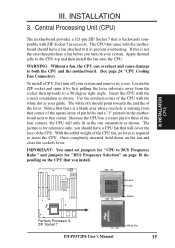
... is required to both the CPU and the motherboard. (See page 24 "CPU Cooling Fan Connector). Lever Lock Blank Pentium Processor & ZIF Socket 7 White Dot P/I-P55T2P4 User's Manual 15
... is required to both the CPU and the motherboard. (See page 24 "CPU Cooling Fan Connector). Lever Lock Blank Pentium Processor & ZIF Socket 7 White Dot P/I-P55T2P4 User's Manual 15