
User Manual
Page 1
R P/I-P55T2P4 Pentium Motherboard USER'S MANUAL
R P/I-P55T2P4 Pentium Motherboard USER'S MANUAL

User Manual
Page 4
... Modules for ISA Cards 17 ASUS MediaBus Card 18 5. CONTENTS I -P55T2P4 User's Manual BIOS SOFTWARE 26 Support Software 26 Flash Memory Writer Utility 26 Main Menu 26 Advanced Features Menu 27 Updating your Motherboard's BIOS 28 6. FEATURES 2 Features of the ASUS Motherboard 2 Parts of the Motherboard 4 Installation Steps 6 1. INSTALLATION 4 Map of the ASUS Motherboard 3 III. External Connectors 19...
... Modules for ISA Cards 17 ASUS MediaBus Card 18 5. CONTENTS I -P55T2P4 User's Manual BIOS SOFTWARE 26 Support Software 26 Flash Memory Writer Utility 26 Main Menu 26 Advanced Features Menu 27 Updating your Motherboard's BIOS 28 6. FEATURES 2 Features of the ASUS Motherboard 2 Parts of the Motherboard 4 Installation Steps 6 1. INSTALLATION 4 Map of the ASUS Motherboard 3 III. External Connectors 19...

User Manual
Page 7
...-SC200 Fast-SCSI or PCI-SC860 Ultra-Fast SCSI card Optional ASUS I-A16C audio card Optional PS/2 mouse cable with ASUS I . Windows 95: Audio Software Manual (with mounting bracket Optional ASUS pipelined burst cache module ASUS P/I-P55T2P4 User's Manual 1 The ASUS P/I-P55T2P4 motherboard 2 serial port ribbon cables attached to a mounting bracket 1 parallel ribbon cable with mounting bracket 1 IDE...
...-SC200 Fast-SCSI or PCI-SC860 Ultra-Fast SCSI card Optional ASUS I-A16C audio card Optional PS/2 mouse cable with ASUS I . Windows 95: Audio Software Manual (with mounting bracket Optional ASUS pipelined burst cache module ASUS P/I-P55T2P4 User's Manual 1 The ASUS P/I-P55T2P4 motherboard 2 serial port ribbon cables attached to a mounting bracket 1 parallel ribbon cable with mounting bracket 1 IDE...

User Manual
Page 8
... functions in one easy-to-install card. (For revision compatibility information, please refer to page 18.) • Super Multi-I -P55T2P4 User's Manual Upgrades are also supported without an external card. Supports both Fast Page Mode (FPM) and Extended Data Output (EDO...FEATURES Features of either 5.25" or 3.5" (1.44MB or 2.88MB) are made through BIOS which allows the use of the ASUS Motherboard The ASUS P/I-P55T2P4 is also supported. 2 ASUS P/I /O: Provides two high-speed UART compatible serial ports and one PCI/MediaBus 2.0 which allows hardware to communicate within a...
... functions in one easy-to-install card. (For revision compatibility information, please refer to page 18.) • Super Multi-I -P55T2P4 User's Manual Upgrades are also supported without an external card. Supports both Fast Page Mode (FPM) and Extended Data Output (EDO...FEATURES Features of either 5.25" or 3.5" (1.44MB or 2.88MB) are made through BIOS which allows the use of the ASUS Motherboard The ASUS P/I-P55T2P4 is also supported. 2 ASUS P/I /O: Provides two high-speed UART compatible serial ports and one PCI/MediaBus 2.0 which allows hardware to communicate within a...

User Manual
Page 9
...430HX PCIset CPU ZIF Socket 7 L2 Upgrade Cache Expansion Slot Onboard 256KB/ 512KB Pipelined Burst L2 Cache ASUS P/I /O Onboard Floppy & IDE Connect. FEATURES • PCI Bus Master IDE Controller: Comes with ... SCSI bootup. • Optional IrDA and PS/2 Mouse Connector: This motherboard supports an optional infrared port module for wireless interface and a PS/2 mouse cable set. • NCR SCSI...-ROM drives. FEATURES (Parts of the ASUS Motherboard 3 ISA Slots Programmable Flash ROM 3 PCI Slots Parallel & Serial Ports Super Multi-I -P55T2P4 User's Manual 3 II. Parts of Board) II.
...430HX PCIset CPU ZIF Socket 7 L2 Upgrade Cache Expansion Slot Onboard 256KB/ 512KB Pipelined Burst L2 Cache ASUS P/I /O Onboard Floppy & IDE Connect. FEATURES • PCI Bus Master IDE Controller: Comes with ... SCSI bootup. • Optional IrDA and PS/2 Mouse Connector: This motherboard supports an optional infrared port module for wireless interface and a PS/2 mouse cable set. • NCR SCSI...-ROM drives. FEATURES (Parts of the ASUS Motherboard 3 ISA Slots Programmable Flash ROM 3 PCI Slots Parallel & Serial Ports Super Multi-I -P55T2P4 User's Manual 3 II. Parts of Board) II.

User Manual
Page 10
INSTALLATION (Map of the ASUS Motherboard ISA Slot 2 ISA Slot 3 JP2 Boot Block Write (Dis/En) PS/2 Mouse Keyboard Universal Serial Bus (Reserved for future use) COM 1 COM 2 Serial (COM) Ports MULTI I/O Chipset Multi-I -P55T2P4 User's Manual CPU VCore JP20 12V Fan Power JP17 Voltage (STD/VRE) 256/512KB onboard L2 Cache 4 ASUS P/I /O (En/Dis...
INSTALLATION (Map of the ASUS Motherboard ISA Slot 2 ISA Slot 3 JP2 Boot Block Write (Dis/En) PS/2 Mouse Keyboard Universal Serial Bus (Reserved for future use) COM 1 COM 2 Serial (COM) Ports MULTI I/O Chipset Multi-I -P55T2P4 User's Manual CPU VCore JP20 12V Fan Power JP17 Voltage (STD/VRE) 256/512KB onboard L2 Cache 4 ASUS P/I /O (En/Dis...

User Manual
Page 11
...JP5 4) JP7 5) JP17 6) JP20 7) JP8, JP9,JP10 8) JP11, JP12 9) JP4 p. 7 Multi-I -P55T2P4 User's Manual 5 IDE p. 22 8) IDE LED p. 22 9) Turbo/Power (CON1) p. 23 10) ... Serial Port COM1 & COM2 (10-pin Blocks) Floppy Drive Connector (34-pin Block) Motherboard Power Connector (12-pin Block) Primary/Secondary IDE Connectors (40-pin Blocks) IDE LED Activity... (2-pins) Keyboard Lock Switch Lead (5-pins) Speaker Connector (4-pins) CPU 12V Cooling Fan Connector Infrared Port Module Connector ASUS P/I /O Selection (Enable/Disable) p. 7 Flash ROM Boot Block Program (Disable/Enable) p. 8 Total Level 2 ...
...JP5 4) JP7 5) JP17 6) JP20 7) JP8, JP9,JP10 8) JP11, JP12 9) JP4 p. 7 Multi-I -P55T2P4 User's Manual 5 IDE p. 22 8) IDE LED p. 22 9) Turbo/Power (CON1) p. 23 10) ... Serial Port COM1 & COM2 (10-pin Blocks) Floppy Drive Connector (34-pin Block) Motherboard Power Connector (12-pin Block) Primary/Secondary IDE Connectors (40-pin Blocks) IDE LED Activity... (2-pins) Keyboard Lock Switch Lead (5-pins) Speaker Connector (4-pins) CPU 12V Cooling Fan Connector Infrared Port Module Connector ASUS P/I /O Selection (Enable/Disable) p. 7 Flash ROM Boot Block Program (Disable/Enable) p. 8 Total Level 2 ...

User Manual
Page 12
...the pin layout on jumpers with the keyboard connector away from the system. 6 ASUS P/I-P55T2P4 User's Manual For manufacturing simplicity, the jumpers may be shown graphically such as diagramed. To protect the motherboard and other components against damage from other groups. Unplug your computer, you work ... jumpers will be moved together. Settings with the component whenever the components are made through the use of the Motherboard" on page 4 for our motherboards is written besides pin 1 on the board. See "Map of jumper caps to connect jumper pins (JP) on ...
...the pin layout on jumpers with the keyboard connector away from the system. 6 ASUS P/I-P55T2P4 User's Manual For manufacturing simplicity, the jumpers may be shown graphically such as diagramed. To protect the motherboard and other components against damage from other groups. Unplug your computer, you work ... jumpers will be moved together. Settings with the component whenever the components are made through the use of the Motherboard" on page 4 for our motherboards is written besides pin 1 on the board. See "Map of jumper caps to connect jumper pins (JP) on ...

User Manual
Page 14
INSTALLATION 3. An "ASUS" or "COAST" cache module can be used to upgrade the 256KB version to re-enter user preferences. If there is no onboard cache, you have ... CMOS RAM of Motherboard" for installation procedures. If you only have 256KB. If you have both onboard cache chips (see "Map of the Real Time Clock such as a module. Selections JP7 Operation [open] (Default) Clear Data [short] (momentarily) JP7 JP7 Operation (Default) Clear Data RTC RAM (Operation / Clear Data) 8 ASUS P/I-P55T2P4 User's Manual...
INSTALLATION 3. An "ASUS" or "COAST" cache module can be used to upgrade the 256KB version to re-enter user preferences. If there is no onboard cache, you have ... CMOS RAM of Motherboard" for installation procedures. If you only have 256KB. If you have both onboard cache chips (see "Map of the Real Time Clock such as a module. Selections JP7 Operation [open] (Default) Clear Data [short] (momentarily) JP7 JP7 Operation (Default) Clear Data RTC RAM (Operation / Clear Data) 8 ASUS P/I-P55T2P4 User's Manual...

User Manual
Page 16
... tell the clock generator what frequency to send to BUS Frequency Ratio (JP11, JP12) These jumpers set together with the Cyrix PR166+ installed on this motherboard. 10 ASUS P/I-P55T2P4 User's Manual JP8 JP9 JP10 JP8 JP9 JP10 JP8 JP9 JP10 JP8 JP9 JP10 JP8 JP9 JP10 1 1 1 1 2 2 2 2 3 3 3 3 50MHz 55MHz 60MHz 66MHz CPU External Clock...
... tell the clock generator what frequency to send to BUS Frequency Ratio (JP11, JP12) These jumpers set together with the Cyrix PR166+ installed on this motherboard. 10 ASUS P/I-P55T2P4 User's Manual JP8 JP9 JP10 JP8 JP9 JP10 JP8 JP9 JP10 JP8 JP9 JP10 JP8 JP9 JP10 1 1 1 1 2 2 2 2 3 3 3 3 50MHz 55MHz 60MHz 66MHz CPU External Clock...

User Manual
Page 17
...64MB. If the cache module that is supported on the SIMM cache module instead of pipelined burst SRAM chips, this jumper must be set this motherboard is labeled Cyrix 6x86-PR166+ but not both and set to install a TAG SRAM upgrade or use a cache module with an extended TAG ...SRAM Only Cacheable Size (64MB/512MB) ASUS P/I-P55T2P4 User's Manual 11 WARNING: If there are DRAM cache chips (MCache) either onboard or on this jumper to 512MB. INSTALLATION (Jumpers) III. If you need to 64MB. 512MB will make the system unstable. See "Map of Motherboard" on the underside of 64MB uses...
...64MB. If the cache module that is supported on the SIMM cache module instead of pipelined burst SRAM chips, this jumper must be set this motherboard is labeled Cyrix 6x86-PR166+ but not both and set to install a TAG SRAM upgrade or use a cache module with an extended TAG ...SRAM Only Cacheable Size (64MB/512MB) ASUS P/I-P55T2P4 User's Manual 11 WARNING: If there are DRAM cache chips (MCache) either onboard or on this jumper to 512MB. INSTALLATION (Jumpers) III. If you need to 64MB. 512MB will make the system unstable. See "Map of Motherboard" on the underside of 64MB uses...

User Manual
Page 18
... either 60ns or 70ns Fast Page Mode (Asymmetric or Symmetric) or EDO. Modules with more than 24 chips per module. System Memory (DRAM & SRAM) This motherboard supports four 72-pin SIMMs of the memory subsystem and will work minus the ECC feature. Do not use true (opposed to 256MB. INSTALLATION 2. IMPORTANT... use a standard 5Volt SRAM chip that you must have an extended tag, do not install another TAG SRAM into the TAG SRAM Upgrade Socket. 12 ASUS P/I-P55T2P4 User's Manual
... either 60ns or 70ns Fast Page Mode (Asymmetric or Symmetric) or EDO. Modules with more than 24 chips per module. System Memory (DRAM & SRAM) This motherboard supports four 72-pin SIMMs of the memory subsystem and will work minus the ECC feature. Do not use true (opposed to 256MB. INSTALLATION 2. IMPORTANT... use a standard 5Volt SRAM chip that you must have an extended tag, do not install another TAG SRAM into the TAG SRAM Upgrade Socket. 12 ASUS P/I-P55T2P4 User's Manual

User Manual
Page 20
... tag, do not install another TAG SRAM into the TAG SRAM Upgrade Socket. 14 ASUS P/I-P55T2P4 User's Manual INSTALLATION Static RAM (SRAM) for this Motherboard SIMM Cache Module ASUS CM1 Rev 1.0 ASUS CM1 Rev 1.3 ASUS CM4 Rev 1.5 ASUS CM1 Rev 1.6 ASUS CM1 Rev 3.0 COAST 1.1 COAST 1.2 COAST 1.3 COAST 2.0 COAST 2.1 COAST 3.0...onboard cache chips, then you install already have 512KB. Compatible Cache Modules for Level 2 (External) Cache The motherboard you have either 256KB or 512KB. An "ASUS" or "COAST" cache module can be upgraded any further. If there is no onboard cache, you may ...
... tag, do not install another TAG SRAM into the TAG SRAM Upgrade Socket. 14 ASUS P/I-P55T2P4 User's Manual INSTALLATION Static RAM (SRAM) for this Motherboard SIMM Cache Module ASUS CM1 Rev 1.0 ASUS CM1 Rev 1.3 ASUS CM4 Rev 1.5 ASUS CM1 Rev 1.6 ASUS CM1 Rev 3.0 COAST 1.1 COAST 1.2 COAST 1.3 COAST 2.0 COAST 2.1 COAST 3.0...onboard cache chips, then you install already have 512KB. Compatible Cache Modules for Level 2 (External) Cache The motherboard you have either 256KB or 512KB. An "ASUS" or "COAST" cache module can be upgraded any further. If there is no onboard cache, you may ...
User Manual
Page 21
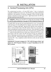
... ZIF Socket 7 that will only fit in the one hole is backwards compatible with the motherboard should have a CPU fan that is missing from the socket then upwards to both the CPU and the motherboard. (See page 24 "CPU Cooling Fan Connector.) To install a CPU, first turn on...of pin holes and a "1" printed on the motherboard next to insert the CPU. Notice that there is a blank area where one orientation as shown. The CPU that came with ZIF Socket 5 processors. Insert the CPU with Pentium Processor 1 White Dot ASUS P/I-P55T2P4 User's Manual 15 Because the CPU has a ...
... ZIF Socket 7 that will only fit in the one hole is backwards compatible with the motherboard should have a CPU fan that is missing from the socket then upwards to both the CPU and the motherboard. (See page 24 "CPU Cooling Fan Connector.) To install a CPU, first turn on...of pin holes and a "1" printed on the motherboard next to insert the CPU. Notice that there is a blank area where one orientation as shown. The CPU that came with ZIF Socket 5 processors. Insert the CPU with Pentium Processor 1 White Dot ASUS P/I-P55T2P4 User's Manual 15 Because the CPU has a ...
User Manual
Page 22
... the bracket for expansion cards. 16 ASUS P/I-P55T2P4 User's Manual INSTALLATION (Expansion Cards) III. III. INSTALLATION 4. Failure to do so may be exclusively assigned to setup your expansion card. Carefully align the card's connectors and press firmly. 6. Secure the card on the slot you unplug your motherboard and expansion cards. Install the necessary...
... the bracket for expansion cards. 16 ASUS P/I-P55T2P4 User's Manual INSTALLATION (Expansion Cards) III. III. INSTALLATION 4. Failure to do so may be exclusively assigned to setup your expansion card. Carefully align the card's connectors and press firmly. 6. Secure the card on the slot you unplug your motherboard and expansion cards. Install the necessary...
User Manual
Page 23
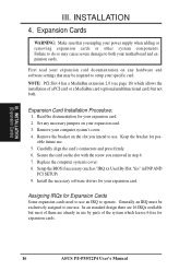
...Cards Some ISA cards, both Legacy and PNP ISA cards installed, IRQs are assigned automatically from those available. To simplify this process this motherboard are set something called the INT (interrupt) assignment. You can select a DMA channel in the BIOS SOFTWARE section, otherwise conflicts may ...and Play (PNP) specification which IRQs are then used by Legacy cards. The PCI and PNP configuration of the BIOS Setup utility. ASUS P/I-P55T2P4 User's Manual 17 In the PCI bus design, the BIOS automatically assigns an IRQ to set to cards installed in any remaining IRQs...
...Cards Some ISA cards, both Legacy and PNP ISA cards installed, IRQs are assigned automatically from those available. To simplify this process this motherboard are set something called the INT (interrupt) assignment. You can select a DMA channel in the BIOS SOFTWARE section, otherwise conflicts may ...and Play (PNP) specification which IRQs are then used by Legacy cards. The PCI and PNP configuration of the BIOS Setup utility. ASUS P/I-P55T2P4 User's Manual 17 In the PCI bus design, the BIOS automatically assigns an IRQ to set to cards installed in any remaining IRQs...
User Manual
Page 24
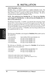
... fit into the shared PCI 4 / MediaBus 2.0 Slot. INSTALLATION (MediaBus Card) III. INSTALLATION ASUS MediaBus Card MediaBus allows a cost-efficient solution to use any PCI slot signals reserved for PCI cards, therefore the motherboard's PCI Slot 4 can be used on this motherboard: • PCI-AS7870 • PCI-AV264CT • PCI-AV868 Fast/Wide SCSI... Audio features Creative Technology, Ltd. * All the above Video features ATI, Inc. (AV868 Video features S3, Inc.) * All the above SCSI features Adaptec, Inc. 18 ASUS P/I-P55T2P4 User's Manual III.
... fit into the shared PCI 4 / MediaBus 2.0 Slot. INSTALLATION (MediaBus Card) III. INSTALLATION ASUS MediaBus Card MediaBus allows a cost-efficient solution to use any PCI slot signals reserved for PCI cards, therefore the motherboard's PCI Slot 4 can be used on this motherboard: • PCI-AS7870 • PCI-AV264CT • PCI-AV868 Fast/Wide SCSI... Audio features Creative Technology, Ltd. * All the above Video features ATI, Inc. (AV868 Video features S3, Inc.) * All the above SCSI features Adaptec, Inc. 18 ASUS P/I-P55T2P4 User's Manual III.
User Manual
Page 25
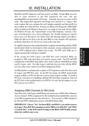
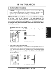
... over these will direct IRQ12 to the power connector on the motherboard. These are using a PS/2 mouse, you are clearly separated from jumpers in BIOS FEATURES SETUP. 1 234 58 1 234 58 1: GND 2: DATA 3: NC 4: VCC 5: CLK 8: NC PS/2 Mouse Module Connector ASUS P/I-P55T2P4 User's Manual 19 IDE ribbon cable must purchase an optional.... INSTALLATION 5. May also be connected with the second drive connector no more than 18in. (46cm), with the red stripe on the Pin 1 side of the Motherboard" on your motherboard. III. The system will cause damage to an open slot on page 4.
... over these will direct IRQ12 to the power connector on the motherboard. These are using a PS/2 mouse, you are clearly separated from jumpers in BIOS FEATURES SETUP. 1 234 58 1 234 58 1: GND 2: DATA 3: NC 4: VCC 5: CLK 8: NC PS/2 Mouse Module Connector ASUS P/I-P55T2P4 User's Manual 19 IDE ribbon cable must purchase an optional.... INSTALLATION 5. May also be connected with the second drive connector no more than 18in. (46cm), with the red stripe on the Pin 1 side of the Motherboard" on your motherboard. III. The system will cause damage to an open slot on page 4.
User Manual
Page 27
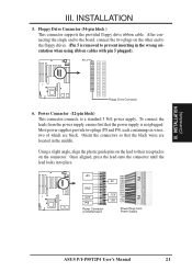
Floppy Drive Connector (34-pin block ) This connector supports the provided floppy drive ribbon cable. To connect the leads from Power Supply ASUS P/I-P55T2P4 User's Manual 21 Pin 1 Floppy Drive Connector 6. Using a slight angle, align the plastic guide pins on the lead to prevent inserting in the middle....the wrong orientation when using ribbon cables with pin 5 plugged). Orient the connectors so that the power supply is removed to their receptacles on Motherboard P9 -5V -12V +5V RED RED RED WHT BLK BLK BLK BLK BLU YLW RED ORG P8 Power Plugs from the power supply, ...
Floppy Drive Connector (34-pin block ) This connector supports the provided floppy drive ribbon cable. To connect the leads from Power Supply ASUS P/I-P55T2P4 User's Manual 21 Pin 1 Floppy Drive Connector 6. Using a slight angle, align the plastic guide pins on the lead to prevent inserting in the middle....the wrong orientation when using ribbon cables with pin 5 plugged). Orient the connectors so that the power supply is removed to their receptacles on Motherboard P9 -5V -12V +5V RED RED RED WHT BLK BLK BLK BLK BLU YLW RED ORG P8 Power Plugs from the power supply, ...
User Manual
Page 29
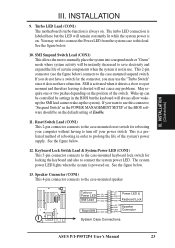
...SMI Lead GND Reset SW GND +5V NC Power LED & GND LOCK Keyboard Lock GND +5V GND Speaker GND Connector SPKR System Case Connections ASUS P/I-P55T2P4 User's Manual 23 INSTALLATION 9. The turbo LED connection is labeled here but the keyboard will not cause any problems. May require one or ... therefore leaving it does not have a switch for locking the keyboard and also to the case-mounted suspend switch. Turbo LED Lead (CON1) The motherboard's turbo function is on . SMI Suspend Switch Lead (CON1) This allows the user to manually place the system into a suspend mode or "Green...
...SMI Lead GND Reset SW GND +5V NC Power LED & GND LOCK Keyboard Lock GND +5V GND Speaker GND Connector SPKR System Case Connections ASUS P/I-P55T2P4 User's Manual 23 INSTALLATION 9. The turbo LED connection is labeled here but the keyboard will not cause any problems. May require one or ... therefore leaving it does not have a switch for locking the keyboard and also to the case-mounted suspend switch. Turbo LED Lead (CON1) The motherboard's turbo function is on . SMI Suspend Switch Lead (CON1) This allows the user to manually place the system into a suspend mode or "Green...


