User Manual
Page 32
Chapter summary 2 2.1 Before you proceed 2-1 2.2 Motherboard overview 2-2 2.3 Building your computer system 2-40 2.4 Starting up for the first time 2-56 2.5 Turning off the computer 2-57 ASUS Maximus IV Extreme
Chapter summary 2 2.1 Before you proceed 2-1 2.2 Motherboard overview 2-2 2.3 Building your computer system 2-40 2.4 Starting up for the first time 2-56 2.5 Turning off the computer 2-57 ASUS Maximus IV Extreme
User Manual
Page 33
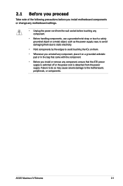
... as the power supply case, to avoid damaging them due to static electricity. • Hold components by the edges to the motherboard, peripherals, or components. ASUS Maximus IV Extreme 2-1 2.1 Before you proceed Take note of the following precautions before touching any component, ensure that the ATX power supply is switched off or the power...
... as the power supply case, to avoid damaging them due to static electricity. • Hold components by the edges to the motherboard, peripherals, or components. ASUS Maximus IV Extreme 2-1 2.1 Before you proceed Take note of the following precautions before touching any component, ensure that the ATX power supply is switched off or the power...
User Manual
Page 35
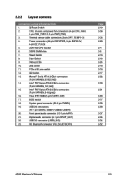
... Bluetooth connector (RC_BLUETOOTH) Page 2-19 2-36 2-35 2-28 2-4 2-5 2-16 2-16 2-24 2-18 2-18 2-17 2-32 2-30 2-31 2-29 2-17 2-39 2-33 2-37 2-34 2-34 2-52 ASUS Maximus IV Extreme 2-3 Debug LEDs 10. System panel connector (20-8 pin PANEL) 19. Q-Reset Switch 2. Marvell® Serial ATA 6.0 Gb/s connectors (7-pin SATA6G_E1/E2 [red]) 14. USB78) 20...
... Bluetooth connector (RC_BLUETOOTH) Page 2-19 2-36 2-35 2-28 2-4 2-5 2-16 2-16 2-24 2-18 2-18 2-17 2-32 2-30 2-31 2-29 2-17 2-39 2-33 2-37 2-34 2-34 2-52 ASUS Maximus IV Extreme 2-3 Debug LEDs 10. System panel connector (20-8 pin PANEL) 19. Q-Reset Switch 2. Marvell® Serial ATA 6.0 Gb/s connectors (7-pin SATA6G_E1/E2 [red]) 14. USB78) 20...

User Manual
Page 37
A DDR3 module is notched differently from a DDR or DDR2 module. 2.2.4 System memory The motherboard comes with four Double Data Rate 3 (DDR3) Dual Inline Memory Modules (DIMM) slots. DO NOT install a DDR or DDR2 memory module to the DDR3 slot. Recommended memory configurations ASUS Maximus IV Extreme 2-5
A DDR3 module is notched differently from a DDR or DDR2 module. 2.2.4 System memory The motherboard comes with four Double Data Rate 3 (DDR3) Dual Inline Memory Modules (DIMM) slots. DO NOT install a DDR or DDR2 memory module to the DDR3 slot. Recommended memory configurations ASUS Maximus IV Extreme 2-5
User Manual
Page 39
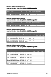
... (Optional) 1 DIMM 2 DIMM 4 DIMM 1.65 • • 1.65 • 1.65 • - • Maximus IV Extreme Motherboard Qualified Vendors Lists (QVL) DDR�3��-�2��1��3�3��M��H���z�...) 4GB(2 x 2GB) DS 8 1.65 • Patriot PVV34G2133C9K(XMP) 4GB ( 2x 2GB ) DS 9-11-9-27 1.66 • ASUS Maximus IV Extreme 2-7 KINGSTON KHX2250C9D3T1K2/4GX(XMP) Size SS/DS Voltage 4GB ( 2x 2GB ) DS 1.65 DIMM socket support (Optional) 1 DIMM 2 DIMM 4 DIMM •...
... (Optional) 1 DIMM 2 DIMM 4 DIMM 1.65 • • 1.65 • 1.65 • - • Maximus IV Extreme Motherboard Qualified Vendors Lists (QVL) DDR�3��-�2��1��3�3��M��H���z�...) 4GB(2 x 2GB) DS 8 1.65 • Patriot PVV34G2133C9K(XMP) 4GB ( 2x 2GB ) DS 9-11-9-27 1.66 • ASUS Maximus IV Extreme 2-7 KINGSTON KHX2250C9D3T1K2/4GX(XMP) Size SS/DS Voltage 4GB ( 2x 2GB ) DS 1.65 DIMM socket support (Optional) 1 DIMM 2 DIMM 4 DIMM •...
User Manual
Page 45
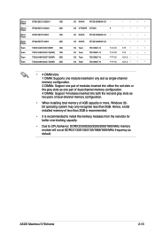
... memory configuration. • When installing total memory of dual-channel memory configuration. 4 DIMMs: Support 4 modules inserted into both the red and gray slots as default. ASUS Maximus IV Extreme 2-13
... memory configuration. • When installing total memory of dual-channel memory configuration. 4 DIMMs: Support 4 modules inserted into both the red and gray slots as default. ASUS Maximus IV Extreme 2-13
User Manual
Page 47
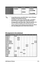
... - shared - - - shared - - - - - - SATA #1 - - - - shared - - - - x8 (Native) - shared - - - - - - shared - - - - - - Dual VGA x8 (Native) - IRQ assignments for better thermal environment. shared - - - - - - shared EHCI#1 (USB2.0) - - - - - - - ASUS Maximus IV Extreme 2-15 PCIEx8_3 - Intel 82583 - - PCIE_X16/8_1 PCIE_X16_2 PCIE_X8_3 PCIE_X16_4 Single VGA x16 (Native) - - - PCIEx16_2 - PCIEx16_4 - EHCI#0 (USB2.0) - - - - - - - Marvell9182 shared - - - - - - - PCIEx1 shared - - - - - - -
... - shared - - - shared - - - - - - SATA #1 - - - - shared - - - - x8 (Native) - shared - - - - - - shared - - - - - - Dual VGA x8 (Native) - IRQ assignments for better thermal environment. shared - - - - - - shared EHCI#1 (USB2.0) - - - - - - - ASUS Maximus IV Extreme 2-15 PCIEx8_3 - Intel 82583 - - PCIE_X16/8_1 PCIE_X16_2 PCIE_X8_3 PCIE_X16_4 Single VGA x16 (Native) - - - PCIEx16_2 - PCIEx16_4 - EHCI#0 (USB2.0) - - - - - - - Marvell9182 shared - - - - - - - PCIEx1 shared - - - - - - -
User Manual
Page 49
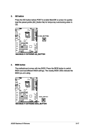
The nearby BIOS LEDs indicate the BIOS you are using. or press it to enable MemOK! BIOS button The motherboard comes with two BIOS. ASUS Maximus IV Extreme 2-17 GO button Press the GO button before POST to quickly load the preset profile (GO_Button file) for temporary overclocking when in OS. 4. Press the BIOS button to switch BIOS and load different BIOS settings. 3.
The nearby BIOS LEDs indicate the BIOS you are using. or press it to enable MemOK! BIOS button The motherboard comes with two BIOS. ASUS Maximus IV Extreme 2-17 GO button Press the GO button before POST to quickly load the preset profile (GO_Button file) for temporary overclocking when in OS. 4. Press the BIOS button to switch BIOS and load different BIOS settings. 3.
User Manual
Page 51
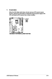
Q reset button When the LN2_Mode switch does not work and your CPU cannot resume function, press the Q reset button to temporarily stop the power supply to the CPU and help the CPU recover from a frozen condition. 7. ASUS Maximus IV Extreme 2-19
Q reset button When the LN2_Mode switch does not work and your CPU cannot resume function, press the Q reset button to temporarily stop the power supply to the CPU and help the CPU recover from a frozen condition. 7. ASUS Maximus IV Extreme 2-19
User Manual
Page 53
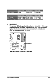
It blinks when data is designed to the motherboard or when the hard disk drive does not function. ASUS Maximus IV Extreme 2-21 DRAM Voltage PCH Voltage PCH PLL Voltage Normal (blue) 1.2�-�1�.6� High (yellow) 1.60625-1.8 Crazy (red) 1.80625-by CPU Normal (blue) High (...
It blinks when data is designed to the motherboard or when the hard disk drive does not function. ASUS Maximus IV Extreme 2-21 DRAM Voltage PCH Voltage PCH PLL Voltage Normal (blue) 1.2�-�1�.6� High (yellow) 1.60625-1.8 Crazy (red) 1.80625-by CPU Normal (blue) High (...

User Manual
Page 55
.... If an error is found , the corresponding LED will continue lighting until the problem is ON, in sleep mode, or in soft‑off mode. ASUS Maximus IV Extreme 2-23 The illustration below shows the location of the onboard power-on switch that lights up to locate the root problem within a second. 8. Q LED Q LEDs...
.... If an error is found , the corresponding LED will continue lighting until the problem is ON, in sleep mode, or in soft‑off mode. ASUS Maximus IV Extreme 2-23 The illustration below shows the location of the onboard power-on switch that lights up to locate the root problem within a second. 8. Q LED Q LEDs...
User Manual
Page 57
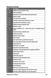
... S3 Resume is stared (S3 Resume PPI is started 3F - 4E OEM post memory initialization codes 4F DXE IPL is called by user (Forced recovery) ASUS Maximus IV Extreme 2-25 Debug table (continued) Code Description 1D - 2A OEM pre-memory initialization codes 2B - 2F Memory initialization 30 Reserved for future AMI progress codes E8...
... S3 Resume is stared (S3 Resume PPI is started 3F - 4E OEM post memory initialization codes 4F DXE IPL is called by user (Forced recovery) ASUS Maximus IV Extreme 2-25 Debug table (continued) Code Description 1D - 2A OEM pre-memory initialization codes 2B - 2F Memory initialization 30 Reserved for future AMI progress codes E8...
User Manual
Page 59
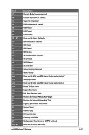
... Initialization System Reset USB hot plug PCI bus hot plug Clean-up of NVRAM Configuration Reset (reset of NVRAM settings) Reserved for future AMI codes ASUS Maximus IV Extreme 2-27
... Initialization System Reset USB hot plug PCI bus hot plug Clean-up of NVRAM Configuration Reset (reset of NVRAM settings) Reserved for future AMI codes ASUS Maximus IV Extreme 2-27

User Manual
Page 61
... 1-2. 3. You must turn ON the computer. 4. The onboard button cell battery powers the RAM data in CMOS. Keep the cap on CLRTC jumper default position. ASUS Maximus IV Extreme 2-29 Turn OFF the computer and unplug the power cord. 2. Plug the power cord and turn off is required to the chipset behavior, AC power...
... 1-2. 3. You must turn ON the computer. 4. The onboard button cell battery powers the RAM data in CMOS. Keep the cap on CLRTC jumper default position. ASUS Maximus IV Extreme 2-29 Turn OFF the computer and unplug the power cord. 2. Plug the power cord and turn off is required to the chipset behavior, AC power...
User Manual
Page 63
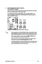
... configurations or the manual bundled in the motherboard support DVD. • When using these connectors, set the SATA Mode in the BIOS to [RAID Mode]. ASUS Maximus IV Extreme 2-31 Intel® P67 Serial ATA 3.0 Gb/s connectors (7-pin SATA3G_3-6 [gray]) These connectors connect to [IDE Mode] by default. Refer to [AHCI Mode]. Refer to...
... configurations or the manual bundled in the motherboard support DVD. • When using these connectors, set the SATA Mode in the BIOS to [RAID Mode]. ASUS Maximus IV Extreme 2-31 Intel® P67 Serial ATA 3.0 Gb/s connectors (7-pin SATA3G_3-6 [gray]) These connectors connect to [IDE Mode] by default. Refer to [AHCI Mode]. Refer to...
User Manual
Page 65
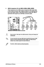
... separately. USB34; These USB connectors comply with USB 2.0 specification that supports up to the USB connector onboard if your chassis supports front panel USB ports. ASUS Maximus IV Extreme 2-33 Doing so will damage the motherboard! Never connect a 1394 cable to a slot opening at the back of the system chassis. USB78) These connectors are...
... separately. USB34; These USB connectors comply with USB 2.0 specification that supports up to the USB connector onboard if your chassis supports front panel USB ports. ASUS Maximus IV Extreme 2-33 Doing so will damage the motherboard! Never connect a 1394 cable to a slot opening at the back of the system chassis. USB78) These connectors are...

User Manual
Page 67
... W) fan power. • If you install two VGA cards, we recommend that the black wire of each cable matches the ground pin of the connector. ASUS Maximus IV Extreme 2-35 7. Do not forget to connect the fan cables to the motherboard connector labeled CHA_FAN1, CHA_FAN2, CHA_FAN3 for better thermal environment.
... W) fan power. • If you install two VGA cards, we recommend that the black wire of each cable matches the ground pin of the connector. ASUS Maximus IV Extreme 2-35 7. Do not forget to connect the fan cables to the motherboard connector labeled CHA_FAN1, CHA_FAN2, CHA_FAN3 for better thermal environment.
User Manual
Page 69
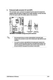
Front panel audio connector (10-1 pin AAFP) This connector is set to [HD]. ASUS Maximus IV Extreme 2-37 if you want to connect a high-definition front panel audio module to this connector, set the item to [HD]; By default, this connector, set ...
Front panel audio connector (10-1 pin AAFP) This connector is set to [HD]. ASUS Maximus IV Extreme 2-37 if you want to connect a high-definition front panel audio module to this connector, set the item to [HD]; By default, this connector, set ...
User Manual
Page 71
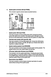
... puts the system in sleep mode. • Hard disk drive activity LED (2-pin IDE_LED) This 2-pin connector is for the chassis-mounted system warning speaker. ASUS Maximus IV Extreme 2-39 11. Connect the chassis power LED cable to the HDD. • System warning speaker (4-pin SPEAKER) This 4-pin connector is for system reboot without...
... puts the system in sleep mode. • Hard disk drive activity LED (2-pin IDE_LED) This 2-pin connector is for the chassis-mounted system warning speaker. ASUS Maximus IV Extreme 2-39 11. Connect the chassis power LED cable to the HDD. • System warning speaker (4-pin SPEAKER) This 4-pin connector is for system reboot without...

User Manual
Page 75
2.3.3 CPU heatsink and fan assembly installation Apply the Thermal Interface Material to the CPU heatsink and CPU before you install the heatsink and fan if necessary. To install the CPU heatsink and fan assembly 1 A 2 B B A 3 ASUS Maximus IV Extreme 2-43
2.3.3 CPU heatsink and fan assembly installation Apply the Thermal Interface Material to the CPU heatsink and CPU before you install the heatsink and fan if necessary. To install the CPU heatsink and fan assembly 1 A 2 B B A 3 ASUS Maximus IV Extreme 2-43


