User Guide
Page 35
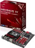
...36 2-38 2-4 2-5 2-16 2-16 2-24 2-18 2-18 2-17 2-32 2-30 2-31 2-29 2-17 2-39 2-33 2-37 2-34 2-34 2-52 ASUS Maximus IV Extreme-Z 2-3 2.2.2 Layout contents Connectors/Jumpers/Switches/Slots 1. GO button 13. Intel® Z68 Serial ATA 3.0 Gb/s connectors (7-pin SATA3G_3-6 [gray]) 16. USB.... USB 3.0 connector (USB3_910) 23. CPU, chassis, and power fan connectors (4-pin CPU_FAN, 4-pin CHA_FAN1-3, 4-pin PWR_FAN) 3. Clear RTC RAM (3-pin CLRTC_SW) 17. System panel connector (20-8 pin PANEL) 19. Debug LEDs 10. BIOS switch 18. Reset Switch 8. Power connectors (...
...36 2-38 2-4 2-5 2-16 2-16 2-24 2-18 2-18 2-17 2-32 2-30 2-31 2-29 2-17 2-39 2-33 2-37 2-34 2-34 2-52 ASUS Maximus IV Extreme-Z 2-3 2.2.2 Layout contents Connectors/Jumpers/Switches/Slots 1. GO button 13. Intel® Z68 Serial ATA 3.0 Gb/s connectors (7-pin SATA3G_3-6 [gray]) 16. USB.... USB 3.0 connector (USB3_910) 23. CPU, chassis, and power fan connectors (4-pin CPU_FAN, 4-pin CHA_FAN1-3, 4-pin PWR_FAN) 3. Clear RTC RAM (3-pin CLRTC_SW) 17. System panel connector (20-8 pin PANEL) 19. Debug LEDs 10. BIOS switch 18. Reset Switch 8. Power connectors (...

User Guide
Page 61
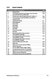
.... Turn OFF the computer and unplug the power cord. 2. Plug the power cord and turn off is required to clear the CMOS RTC RAM data. Keep the cap on CLRTC jumper default position. Hold down and reboot the system so the BIOS can clear the CMOS memory of..., time, and system setup parameters by erasing the CMOS RTC RAM data. Except when clearing the RTC RAM, never remove the cap on pins 2-3 for about 5-10 seconds, then move the jumper again to enable C.P.R. For system failure due to pins 2-3. ASUS Maximus IV Extreme-Z 2-29 function. You must turn ON the computer. 4....
.... Turn OFF the computer and unplug the power cord. 2. Plug the power cord and turn off is required to clear the CMOS RTC RAM data. Keep the cap on CLRTC jumper default position. Hold down and reboot the system so the BIOS can clear the CMOS memory of..., time, and system setup parameters by erasing the CMOS RTC RAM data. Except when clearing the RTC RAM, never remove the cap on pins 2-3 for about 5-10 seconds, then move the jumper again to enable C.P.R. For system failure due to pins 2-3. ASUS Maximus IV Extreme-Z 2-29 function. You must turn ON the computer. 4....
User Guide
Page 93
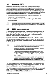
... it lets you want to use as possible. Being a menu-driven program, it back on the system chassis to restart the system. ASUS Maximus IV Extreme-Z 3-1 If you to erase the RTC RAM. Press during the system bootup and requests you wish to enter Setup after changing any BIOS setting, load the default settings to...
... it lets you want to use as possible. Being a menu-driven program, it back on the system chassis to restart the system. ASUS Maximus IV Extreme-Z 3-1 If you to erase the RTC RAM. Press during the system bootup and requests you wish to enter Setup after changing any BIOS setting, load the default settings to...
User Guide
Page 107
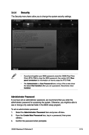
... settings. • If you have set an administrator password, we recommend that you enter the administrator password for information on how to erase the RTC RAM. • The Administrator or User Password items on top of the screen show Installed. ASUS Maximus IV Extreme-Z 3-15 See section 2.7.1 Rear panel connectors for accessing the system.
... settings. • If you have set an administrator password, we recommend that you enter the administrator password for information on how to erase the RTC RAM. • The Administrator or User Password items on top of the screen show Installed. ASUS Maximus IV Extreme-Z 3-15 See section 2.7.1 Rear panel connectors for accessing the system.


