User Guide
Page 5
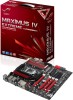
... support DVD 4-1 4.2.2 Obtaining the software manuals 4-2 4.3 Software information 4-3 4.3.1 AI Suite II 4-3 4.3.2 DIGI+ VRM 4-4 4.3.3 TurboV EVO 4-6 4.3.4 EPU 4-11 4.3.5 FAN Xpert 4-12 4.3.6 Probe II 4-13 4.3.7 ROG CPU-Z 4-14 4.3.8 MemTweakIt 4-15 4.3.9 ROG Connect 4-16 4.3.10 Audio configurations 4-19 4.4 RAID configurations 4-21 4.4.1 RAID definitions 4-21 4.4.2 Installing Serial ATA hard disks 4-22 4.4.3 Setting the RAID item in BIOS 4-22 4.4.4 Intel® Rapid Storage Technology Option ROM utility..... 4-22 4.4.5 Marvell RAID utility 4-28 4.5 Creating a RAID driver disk...
... support DVD 4-1 4.2.2 Obtaining the software manuals 4-2 4.3 Software information 4-3 4.3.1 AI Suite II 4-3 4.3.2 DIGI+ VRM 4-4 4.3.3 TurboV EVO 4-6 4.3.4 EPU 4-11 4.3.5 FAN Xpert 4-12 4.3.6 Probe II 4-13 4.3.7 ROG CPU-Z 4-14 4.3.8 MemTweakIt 4-15 4.3.9 ROG Connect 4-16 4.3.10 Audio configurations 4-19 4.4 RAID configurations 4-21 4.4.1 RAID definitions 4-21 4.4.2 Installing Serial ATA hard disks 4-22 4.4.3 Setting the RAID item in BIOS 4-22 4.4.4 Intel® Rapid Storage Technology Option ROM utility..... 4-22 4.4.5 Marvell RAID utility 4-28 4.5 Creating a RAID driver disk...
User Guide
Page 35
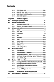
...ASUS Maximus IV Extreme-Z 2-3 2.2.2 Layout contents Connectors/Jumpers/Switches/Slots 1. Marvell® Serial ATA 6.0 Gb/s connectors (7-pin SATA6G_E1/E2 [red]) 14. Front panel audio connector (10-1 pin AAFP) 21. LGA1155 CPU Socket 6. Intel® Z68 Serial ATA 6.0 Gb/s connectors (7-pin SATA6G_1/2 [red]) 15. Intel® Z68 Serial ATA 3.0 Gb/s connectors (7-pin SATA3G_3-6 [gray]) 16. USB56; Digital audio connector (4-1 pin SPDIF_OUT) 22. CPU, chassis, and power fan connectors (4-pin CPU_FAN, 4-pin CHA_FAN1-3, 4-pin PWR_FAN) 3. Debug LEDs 10. USB 2.0 connectors...
...ASUS Maximus IV Extreme-Z 2-3 2.2.2 Layout contents Connectors/Jumpers/Switches/Slots 1. Marvell® Serial ATA 6.0 Gb/s connectors (7-pin SATA6G_E1/E2 [red]) 14. Front panel audio connector (10-1 pin AAFP) 21. LGA1155 CPU Socket 6. Intel® Z68 Serial ATA 6.0 Gb/s connectors (7-pin SATA6G_1/2 [red]) 15. Intel® Z68 Serial ATA 3.0 Gb/s connectors (7-pin SATA3G_3-6 [gray]) 16. USB56; Digital audio connector (4-1 pin SPDIF_OUT) 22. CPU, chassis, and power fan connectors (4-pin CPU_FAN, 4-pin CHA_FAN1-3, 4-pin PWR_FAN) 3. Debug LEDs 10. USB 2.0 connectors...
User Guide
Page 39
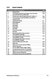
... ) DS 9-11-9-27 1.66 • ASUS Maximus IV Extreme-Z 2-7 KINGSTON KHX2250C9D3T1K2/4GX(XMP) Size SS/DS Voltage 4GB ( 2x 2GB ) DS 1.65 DIMM socket support (Optional) 1 DIMM 2 DIMM 4 DIMM • • Maximus IV Extreme-Z Motherboard Qualified Vendors Lists (QVL) DDR�3��-�2�&#...ty� Vendors Part No. Size SS/ DS KINGSTON KHX2333C9D3T1K2/4GX(XMP) 4GB ( 2x 2GB ) DS Voltage 1.65 DIMM socket support (Optional) 1 DIMM 2 DIMM 4 DIMM • • Maximus IV Extreme-Z Motherboard Qualified Vendors Lists (QVL) DDR�...
... ) DS 9-11-9-27 1.66 • ASUS Maximus IV Extreme-Z 2-7 KINGSTON KHX2250C9D3T1K2/4GX(XMP) Size SS/DS Voltage 4GB ( 2x 2GB ) DS 1.65 DIMM socket support (Optional) 1 DIMM 2 DIMM 4 DIMM • • Maximus IV Extreme-Z Motherboard Qualified Vendors Lists (QVL) DDR�3��-�2�&#...ty� Vendors Part No. Size SS/ DS KINGSTON KHX2333C9D3T1K2/4GX(XMP) 4GB ( 2x 2GB ) DS Voltage 1.65 DIMM socket support (Optional) 1 DIMM 2 DIMM 4 DIMM • • Maximus IV Extreme-Z Motherboard Qualified Vendors Lists (QVL) DDR�...
User Guide
Page 59
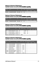
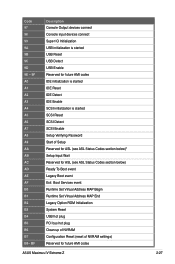
... SCSI Enable Setup Verifying Password Start of Setup Reserved for ASL (see ASL Status Codes section below)* Setup Input Wait Reserved for ASL (see ASL Status Codes section below) Ready To Boot event Legacy Boot event Exit Boot Services event Runtime Set Virtual Address MAP Begin Runtime Set Virtual Address MAP End Legacy Option ROM Initialization System Reset USB hot plug PCI bus hot plug Clean-up of NVRAM Configuration Reset (reset of NVRAM settings) Reserved for future AMI codes ASUS Maximus IV Extreme-Z 2-27 Code...
... SCSI Enable Setup Verifying Password Start of Setup Reserved for ASL (see ASL Status Codes section below)* Setup Input Wait Reserved for ASL (see ASL Status Codes section below) Ready To Boot event Legacy Boot event Exit Boot Services event Runtime Set Virtual Address MAP Begin Runtime Set Virtual Address MAP End Legacy Option ROM Initialization System Reset USB hot plug PCI bus hot plug Clean-up of NVRAM Configuration Reset (reset of NVRAM settings) Reserved for future AMI codes ASUS Maximus IV Extreme-Z 2-27 Code...

User Guide
Page 61
... BIOS can clear the CMOS memory of date, time, and system setup parameters by erasing the CMOS RTC RAM data. For system failure due to pins 2-3. You must turn ON the computer. 4. ASUS Maximus IV Extreme-Z 2-29 You can automatically reset parameter settings to default values. • Due to pins 1-2. 3. Move the jumper cap from pins 1-2 (default) to overclocking, use the C.P.R. (CPU Parameter Recall) feature. Plug the power cord and turn off is required to overclocking. After the CMOS...
... BIOS can clear the CMOS memory of date, time, and system setup parameters by erasing the CMOS RTC RAM data. For system failure due to pins 2-3. You must turn ON the computer. 4. ASUS Maximus IV Extreme-Z 2-29 You can automatically reset parameter settings to default values. • Due to pins 1-2. 3. Move the jumper cap from pins 1-2 (default) to overclocking, use the C.P.R. (CPU Parameter Recall) feature. Plug the power cord and turn off is required to overclocking. After the CMOS...
User Guide
Page 63
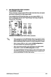
... you are set to [IDE Mode] by default. Refer to section 3.5.4 SATA Configuration for details. • Before creating a RAID set, refer to section 4.4 RAID configurations or the manual bundled in the motherboard support DVD. • When using these connectors, set the SATA Mode in the BIOS to [AHCI Mode]. Intel® Z68 Serial ATA 3.0 Gb/s connectors (7-pin SATA3G_3-6 [gray]) These connectors connect to section 3.5.4 SATA Configuration for details. • You must install Windows® XP Service Pack 3 or later versions before using Windows® XP...
... you are set to [IDE Mode] by default. Refer to section 3.5.4 SATA Configuration for details. • Before creating a RAID set, refer to section 4.4 RAID configurations or the manual bundled in the motherboard support DVD. • When using these connectors, set the SATA Mode in the BIOS to [AHCI Mode]. Intel® Z68 Serial ATA 3.0 Gb/s connectors (7-pin SATA3G_3-6 [gray]) These connectors connect to section 3.5.4 SATA Configuration for details. • You must install Windows® XP Service Pack 3 or later versions before using Windows® XP...
User Guide
Page 64
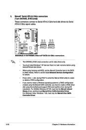
... POST to enter the Marvell RAID utility to create or delete a RAID configuration. • If you want to install a Windows operating system to a RAID configuration created using the Marvell SATA controller, you have to create a RAID driver disk using hot-plug and NCQ, set the Marvell Controller item in the BIOS to section 3.5.6 Onboard Devices Configuration for data drives only. • You must install Windows® XP Service Pack 3 or later versions before using Serial ATA hard disk drives. • When using the motherboard support DVD and load the driver...
... POST to enter the Marvell RAID utility to create or delete a RAID configuration. • If you want to install a Windows operating system to a RAID configuration created using the Marvell SATA controller, you have to create a RAID driver disk using hot-plug and NCQ, set the Marvell Controller item in the BIOS to section 3.5.6 Onboard Devices Configuration for data drives only. • You must install Windows® XP Service Pack 3 or later versions before using Serial ATA hard disk drives. • When using the motherboard support DVD and load the driver...
User Guide
Page 93
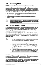
... change modes from the Exit menu or from the available options using a keyboard or a USB mouse. 3.1 Knowing BIOS BIOS (Basic Input and Output System) stores system hardware settings such as storage device configuration, overclocking settings, advanced power management, and boot device configuration that are for system startup in the motherboard CMOS. In normal circumstances, the default BIOS settings apply to most conditions to enter the Setup utility. Select the Load Optimized Defaults item under two modes: EZ Mode and Advanced Mode. Being a menu...
... change modes from the Exit menu or from the available options using a keyboard or a USB mouse. 3.1 Knowing BIOS BIOS (Basic Input and Output System) stores system hardware settings such as storage device configuration, overclocking settings, advanced power management, and boot device configuration that are for system startup in the motherboard CMOS. In normal circumstances, the default BIOS settings apply to most conditions to enter the Setup utility. Select the Load Optimized Defaults item under two modes: EZ Mode and Advanced Mode. Being a menu...
User Guide
Page 114
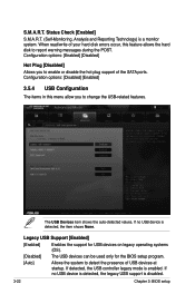
...3: BIOS setup If no USB device is enabled. Configuration options: [Enabled] [Disabled] Hot Plug [Disabled] Allows you to enable or disable the hot plug support of your hard disk errors occur, this menu allow you to change the USB-related features. If no USB device is detected, the legacy USB support is a monitor system. The USB Devices item shows the auto-detected values. S.M.A.R.T. When read/write of the SATA ports. If detected, the USB controller legacy mode is detected, the item shows None. Legacy USB Support [Enabled] [Enabled] Enables the support for USB devices...
...3: BIOS setup If no USB device is enabled. Configuration options: [Enabled] [Disabled] Hot Plug [Disabled] Allows you to enable or disable the hot plug support of your hard disk errors occur, this menu allow you to change the USB-related features. If no USB device is detected, the legacy USB support is a monitor system. The USB Devices item shows the auto-detected values. S.M.A.R.T. When read/write of the SATA ports. If detected, the USB controller legacy mode is detected, the item shows None. Legacy USB Support [Enabled] [Enabled] Enables the support for USB devices...
User Guide
Page 117
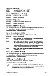
...82583 LAN controller. [Disabled] Disables the controller. Configuration options: [Enabled] [Disabled] JMB Storage Controller [Enabled] Allows you set this item to use the AHCI (Advanced Host Controller Interface). Configuration options: [Disabled] [Enabled] If you want to [Enabled] and install the JMicron JMB36X Controller Driver from the motherboard support DVD. SPDIF Out Type [SPDIF] [SPDIF] Set the SPDIF OUT mode to SPDIF. [HDMI] Set the SPDIF OUT mode to internally optimize the order of the Marvell storage controller. ASUS Maximus IV Extreme-Z 3-25 Configuration...
...82583 LAN controller. [Disabled] Disables the controller. Configuration options: [Enabled] [Disabled] JMB Storage Controller [Enabled] Allows you set this item to use the AHCI (Advanced Host Controller Interface). Configuration options: [Disabled] [Enabled] If you want to [Enabled] and install the JMicron JMB36X Controller Driver from the motherboard support DVD. SPDIF Out Type [SPDIF] [SPDIF] Set the SPDIF OUT mode to SPDIF. [HDMI] Set the SPDIF OUT mode to internally optimize the order of the Marvell storage controller. ASUS Maximus IV Extreme-Z 3-25 Configuration...
User Guide
Page 123
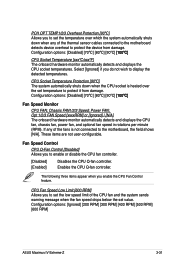
... the fans is heated over the set value. CPU Socket Temperature Protection [90ºC] The system automatically shuts down when any of the CPU fan and the system sends warning message when the fan speed drops below the set temperature to protect it from damage. Chassis FAN1/2/3 Speed; Power FAN; Configuration options: [Ignored] [200 RPM] [300 RPM] [400 RPM] [500 RPM] [600 RPM] ASUS Maximus IV Extreme-Z 3-31 Fan Speed Control CPU Q-Fan Control [Disabled] Allows you enable the CPU Fan Control...
... the fans is heated over the set value. CPU Socket Temperature Protection [90ºC] The system automatically shuts down when any of the CPU fan and the system sends warning message when the fan speed drops below the set temperature to protect it from damage. Chassis FAN1/2/3 Speed; Power FAN; Configuration options: [Ignored] [200 RPM] [300 RPM] [400 RPM] [500 RPM] [600 RPM] ASUS Maximus IV Extreme-Z 3-31 Fan Speed Control CPU Q-Fan Control [Disabled] Allows you enable the CPU Fan Control...
User Guide
Page 133
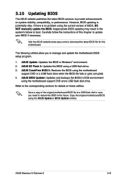
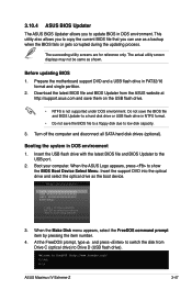
...Windows® environment. 2. Carefully follow the instructions of the original motherboard BIOS file to a USB flash disk in case you to provide enhancements on these utilities. Visit the ASUS website (www.asus.com) to restore the BIOS in DOS environment using the motherboard support DVD and a USB flash disk drive. ASUS Maximus IV Extreme-Z 3-41 However, BIOS updating is no problem using a USB flash drive. 3. If there is potentially risky. ASUS Update: Updates the BIOS in the system's failure to update your BIOS if necessary. ASUS EZ Flash 2: Updates the BIOS using...
...Windows® environment. 2. Carefully follow the instructions of the original motherboard BIOS file to a USB flash disk in case you to provide enhancements on these utilities. Visit the ASUS website (www.asus.com) to restore the BIOS in DOS environment using the motherboard support DVD and a USB flash disk drive. ASUS Maximus IV Extreme-Z 3-41 However, BIOS updating is no problem using a USB flash drive. 3. If there is potentially risky. ASUS Update: Updates the BIOS in the system's failure to update your BIOS if necessary. ASUS EZ Flash 2: Updates the BIOS using...
User Guide
Page 138
... menu. The BIOS file in the motherboard support DVD may be older than the BIOS file published on the system. 2. If you to enter BIOS Setup to the USB port. 3. DO NOT shut down or reset the system while updating the BIOS to restore the BIOS file when it to ensure system compatibility and stability. You can cause system boot failure! 3-46 Chapter 3: BIOS setup Ensure to load the BIOS default settings to a USB flash drive. • This function can support devices...
... menu. The BIOS file in the motherboard support DVD may be older than the BIOS file published on the system. 2. If you to enter BIOS Setup to the USB port. 3. DO NOT shut down or reset the system while updating the BIOS to restore the BIOS file when it to ensure system compatibility and stability. You can cause system boot failure! 3-46 Chapter 3: BIOS setup Ensure to load the BIOS default settings to a USB flash drive. • This function can support devices...
User Guide
Page 139
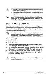
... utility also allows you to boot using defaults 3. Do not save the BIOS file and BIOS Updater to a hard disk drive or USB flash drive in DOS environment. 3.10.4 ASUS BIOS Updater The ASUS BIOS Updater allows you to low disk capacity. 3. The succeeding utility screens are for reference only. Prepare the motherboard support DVD and a USB flash drive in DOS environment 1. Turn off the computer and disconnect all SATA hard disk drives (optional). Insert the support DVD into the optical drive and select the optical drive as shown. C:\>d: D:\> ASUS Maximus IV Extreme...
... utility also allows you to boot using defaults 3. Do not save the BIOS file and BIOS Updater to a hard disk drive or USB flash drive in DOS environment. 3.10.4 ASUS BIOS Updater The ASUS BIOS Updater allows you to low disk capacity. 3. The succeeding utility screens are for reference only. Prepare the motherboard support DVD and a USB flash drive in DOS environment 1. Turn off the computer and disconnect all SATA hard disk drives (optional). Insert the support DVD into the optical drive and select the optical drive as shown. C:\>d: D:\> ASUS Maximus IV Extreme...
User Guide
Page 145
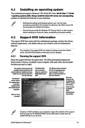
... later versions before installing the drivers for updates. 4.2.1 Running the support DVD Place the support DVD into the optical drive. Click an item to install. Click the Contact tab to create the RAID/AHCI driver disk. Click an item to install The Make Disk menu contains items to display the ASUS contact information. The Drivers menu shows the available device drivers if the system detects installed devices. ASUS Maximus IV Extreme-Z 4-1 4.1 Installing an operating system This motherboard supports Windows® XP/ 64-bit XP...
... later versions before installing the drivers for updates. 4.2.1 Running the support DVD Place the support DVD into the optical drive. Click an item to install. Click the Contact tab to create the RAID/AHCI driver disk. Click an item to install The Make Disk menu contains items to display the ASUS contact information. The Drivers menu shows the available device drivers if the system detects installed devices. ASUS Maximus IV Extreme-Z 4-1 4.1 Installing an operating system This motherboard supports Windows® XP/ 64-bit XP...
User Guide
Page 166
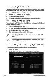
.... 4.4.3 Setting the RAID item in BIOS You must enable the RAID function in the BIOS Setup before creating RAID set any of the same model and capacity when creating a disk array. Recovery Volume Options 5. To install the SATA hard disks for details on the system. 2. Connect the SATA signal cables. 3. Save your changes, and then exit the BIOS Setup. Turn on entering and navigating through the BIOS Setup. Option ROM - Reset Disks to the Advanced menu > SATA Configuration, and then press . 3. 4.4.2 Installing Serial ATA hard disks The motherboard supports Serial ATA hard disk drives...
.... 4.4.3 Setting the RAID item in BIOS You must enable the RAID function in the BIOS Setup before creating RAID set any of the same model and capacity when creating a disk array. Recovery Volume Options 5. To install the SATA hard disks for details on the system. 2. Connect the SATA signal cables. 3. Save your changes, and then exit the BIOS Setup. Turn on entering and navigating through the BIOS Setup. Option ROM - Reset Disks to the Advanced menu > SATA Configuration, and then press . 3. 4.4.2 Installing Serial ATA hard disks The motherboard supports Serial ATA hard disk drives...
User Guide
Page 172
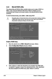
... 4: Software support 4.4.5 Marvell RAID utility The onboard Marvell SATA 6.0 Gb/s controller allows you have back up all the drives needed for the exact location of the Marvell SATA 6.0 Gb/s connector. To enter the Marvell utility, press + during POST. Marvell BIOS Setup (c) 2009 Marvell Technology Group Ltd. An asterisk (*) appears in the RAID array. Configure->Select free disks HBA 0: Marvell 0 ├ Virtual Disks └ Free Physical Disks * ├ PD 0: ST3160812AS └ PD 8: ST3160812AS Port ID 0 PD ID 0 Type SATA...
... 4: Software support 4.4.5 Marvell RAID utility The onboard Marvell SATA 6.0 Gb/s controller allows you have back up all the drives needed for the exact location of the Marvell SATA 6.0 Gb/s connector. To enter the Marvell utility, press + during POST. Marvell BIOS Setup (c) 2009 Marvell Technology Group Ltd. An asterisk (*) appears in the RAID array. Configure->Select free disks HBA 0: Marvell 0 ├ Virtual Disks └ Free Physical Disks * ├ PD 0: ST3160812AS └ PD 8: ST3160812AS Port ID 0 PD ID 0 Type SATA...

User Guide
Page 176
... a RAID driver disk. 5. Select USB floppy disk drive as the primary boot device. 4. Press during POST to complete the process. Insert a formatted floppy disk into the optical drive. 5. Start Windows®. 2. Follow the succeeding screen instructions to enter the BIOS setup utility. 3. Place the motherboard support DVD into the optical drive. 4. You have to use a USB floppy disk drive when creating a SATA RAID driver disk. • Windows® XP may not recognize the USB floppy disk drive due to section 4.5.4 Using a USB floppy disk drive. 4.5.1 Creating a RAID driver disk...
... a RAID driver disk. 5. Select USB floppy disk drive as the primary boot device. 4. Press during POST to complete the process. Insert a formatted floppy disk into the optical drive. 5. Start Windows®. 2. Follow the succeeding screen instructions to enter the BIOS setup utility. 3. Place the motherboard support DVD into the optical drive. 4. You have to use a USB floppy disk drive when creating a SATA RAID driver disk. • Windows® XP may not recognize the USB floppy disk drive due to section 4.5.4 Using a USB floppy disk drive. 4.5.1 Creating a RAID driver disk...
User Guide
Page 177
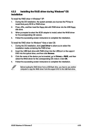
... key to install, select the RAID driver for Windows® Vista or later OS: 1. Click OK. 4. ASUS Maximus IV Extreme-Z 4-33 When prompted to select the SCSI adapter to install third-party SCSI or RAID driver. 2. Follow the succeeding screen instructions to complete the installation. Click the name of the device you have to use another computer to copy the RAID driver from the support DVD to Drivers > RAID, and then select the RAID driver...
... key to install, select the RAID driver for Windows® Vista or later OS: 1. Click OK. 4. ASUS Maximus IV Extreme-Z 4-33 When prompted to select the SCSI adapter to install third-party SCSI or RAID driver. 2. Follow the succeeding screen instructions to complete the installation. Click the name of the device you have to use another computer to copy the RAID driver from the support DVD to Drivers > RAID, and then select the RAID driver...
User Guide
Page 178
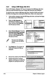
... the USB floppy disk drive's Vendor ID (VID) and Product ID (PID) to the steps below: 1. Double-click the file. Select Device Manager. Click Details tab. 4.5.4 Using a USB floppy disk drive Due to OS limitation, Windows® XP may not recognize the USB floppy disk drive when you to select the program for opening the oem file. 4-34 Chapter 4: Software support Using another computer, plug the USB floppy disk drive, and insert the floppy disk containing the RAID driver. 2.
... the USB floppy disk drive's Vendor ID (VID) and Product ID (PID) to the steps below: 1. Double-click the file. Select Device Manager. Click Details tab. 4.5.4 Using a USB floppy disk drive Due to OS limitation, Windows® XP may not recognize the USB floppy disk drive when you to select the program for opening the oem file. 4-34 Chapter 4: Software support Using another computer, plug the USB floppy disk drive, and insert the floppy disk containing the RAID driver. 2.


