User Manual
Page 3
TPU (TurboV Processing Unit) & EPU (Energy Processing Unit 1-3 1.3.3 ASUS Innovative Design 1-3 1.3.4 ASUS unique features 1-3 Chapter 2: Hardware information 2.1 Before you proceed 2-1 2.2 Motherboard overview 2-2 2.2.1 Motherboard layout 2-2 2.2.2 Central Processing Unit (CPU 2-4 2.2.3 System memory 2-5 2.2.4 Expansion slots 2-11 2.2.5 Jumper 2-13 2.2.6 Onboard switches 2-14 2.2.7 Onboard LEDs 2-15 2.2.8 Internal connectors 2-16 2.3 Building your computer system 2-21 2.3.1 Additional tools and components to...
TPU (TurboV Processing Unit) & EPU (Energy Processing Unit 1-3 1.3.3 ASUS Innovative Design 1-3 1.3.4 ASUS unique features 1-3 Chapter 2: Hardware information 2.1 Before you proceed 2-1 2.2 Motherboard overview 2-2 2.2.1 Motherboard layout 2-2 2.2.2 Central Processing Unit (CPU 2-4 2.2.3 System memory 2-5 2.2.4 Expansion slots 2-11 2.2.5 Jumper 2-13 2.2.6 Onboard switches 2-14 2.2.7 Onboard LEDs 2-15 2.2.8 Internal connectors 2-16 2.3 Building your computer system 2-21 2.3.1 Additional tools and components to...
User Manual
Page 19
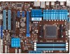
... SB950 Serial ATA 6.0 Gb/s connectors (7-pin SATA6G_1~6) 8. Standby power LED (SB_PWR) 9. Clear RTC RAM (3-pin CLRTC) 11. Serial port connector (10-1 pin COM1) 13. Front panel audio connector (10-1 pin AAFP) 14. DRAM LED (DRAM_LED) 6. switch 7. System panel connector (20-8 pin PANEL...) 10. Digital audio connector (4-1 pin SPDIF_OUT) Page 2-18 2-19 2-4 2-5 2-15 2-14 2-16 2-15 2-20 2-13 2-17 2-16 2-17 2-18 Chapter 2 ASUS M5A97 2-3 AM3+ CPU Socket 4. USB connectors...
... SB950 Serial ATA 6.0 Gb/s connectors (7-pin SATA6G_1~6) 8. Standby power LED (SB_PWR) 9. Clear RTC RAM (3-pin CLRTC) 11. Serial port connector (10-1 pin COM1) 13. Front panel audio connector (10-1 pin AAFP) 14. DRAM LED (DRAM_LED) 6. switch 7. System panel connector (20-8 pin PANEL...) 10. Digital audio connector (4-1 pin SPDIF_OUT) Page 2-18 2-19 2-4 2-5 2-15 2-14 2-16 2-15 2-20 2-13 2-17 2-16 2-17 2-18 Chapter 2 ASUS M5A97 2-3 AM3+ CPU Socket 4. USB connectors...
User Manual
Page 30
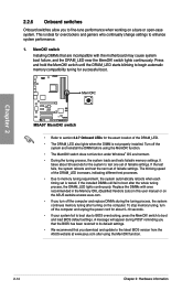
...This is not properly installed. To stop memory tuning, turn off the computer and unplug the power cord for successful boot. switch • Refer to section 2.2.7 Onboard LEDs for the exact location of failsafe settings. switch to memory tuning requirement, the system automatically ...ones recommended in the Memory QVL (Qualified Vendors Lists) in this user manual or on the ASUS website at www.asus.com after using the MemOK! function. • The MemOK! M5A97 M5A97 MemOK! function. 2-14 Chapter 2: Hardware information switch does not function under Windows® OS ...
...This is not properly installed. To stop memory tuning, turn off the computer and unplug the power cord for successful boot. switch • Refer to section 2.2.7 Onboard LEDs for the exact location of failsafe settings. switch to memory tuning requirement, the system automatically ...ones recommended in the Memory QVL (Qualified Vendors Lists) in this user manual or on the ASUS website at www.asus.com after using the MemOK! function. • The MemOK! M5A97 M5A97 MemOK! function. 2-14 Chapter 2: Hardware information switch does not function under Windows® OS ...
User Manual
Page 31
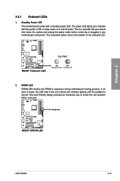
M5A97 M5A97 Onboard LED SB_PWR ON OFF Standby Power Powered Off 2. DRAM LED M5A97 M5A97 DRAM LED ASUS M5A97 2-15 The green LED lights up to indicate that you should shut down the system and unplug the power cable before removing or plugging in any motherboard component. If an error is found, the LED next to locate the root problem within a second. The illustration below...
M5A97 M5A97 Onboard LED SB_PWR ON OFF Standby Power Powered Off 2. DRAM LED M5A97 M5A97 DRAM LED ASUS M5A97 2-15 The green LED lights up to indicate that you should shut down the system and unplug the power cable before removing or plugging in any motherboard component. If an error is found, the LED next to locate the root problem within a second. The illustration below...

User Manual
Page 36
...-mounted system warning speaker. Chapter 2 8. PLED SPEAKER PLED+ PLED+5V Ground Ground Speaker PANEL PIN 1 IDE_LED+ IDE_LED- PWR Ground Reset Ground M5A97 IDE_LED PWRSW RESET M5A97 System panel connector • System power LED (2-pin PLED) This 2-pin connector is for the chassis-mounted reset button for system reboot without turning off button (2-pin PWRSW...
...-mounted system warning speaker. Chapter 2 8. PLED SPEAKER PLED+ PLED+5V Ground Ground Speaker PANEL PIN 1 IDE_LED+ IDE_LED- PWR Ground Reset Ground M5A97 IDE_LED PWRSW RESET M5A97 System panel connector • System power LED (2-pin PLED) This 2-pin connector is for the chassis-mounted reset button for system reboot without turning off button (2-pin PWRSW...

User Manual
Page 52
...protector. 5. After applying power, the system power LED on the system front panel case lights up or change from the time you press the ATX power button. If you do not see the BIOS beep codes table below) or additional messages appear on the screen. Connect the power cord to disabled No... 2.5 Turning off mode, depending on the BIOS setting. For systems with the "green" standards or if it has a "power standby" feature, the monitor LED may have failed a power-on test. While the tests are off mode regardless of the system chassis. 4. BIOS Beep One short beep One continuous beep ...
...protector. 5. After applying power, the system power LED on the system front panel case lights up or change from the time you press the ATX power button. If you do not see the BIOS beep codes table below) or additional messages appear on the screen. Connect the power cord to disabled No... 2.5 Turning off mode, depending on the BIOS setting. For systems with the "green" standards or if it has a "power standby" feature, the monitor LED may have failed a power-on test. While the tests are off mode regardless of the system chassis. 4. BIOS Beep One short beep One continuous beep ...


