
User Guide
Page 1
M4N78 PRO Motherboard
M4N78 PRO Motherboard

User Guide
Page 3
Contents Contents...iii Notices...v Safety information vi About this guide vi M4N78 PRO specifications summary viii Chapter 1 Product introduction 1.1 Welcome 1-1 1.2 Package contents 1-1 1.3 Special features 1-1 1.4 Before you proceed 1-3 1.5 Motherboard overview 1-4 1.5.1 Placement direction 1-4 1.5.2 Screw holes 1-4 1.5.3 Motherboard layout 1-5 1.5.4 Layout contents 1-5 1.6 Central Processing Unit (CPU 1-6 1.6.1 Installing the CPU 1-6 1.6.2 Installing the heatsink and fan 1-7 1.7 System memory 1-9 1.7.1 Overview 1-9 1.7.2 Memory configurations 1-9 1.7.3 ...
Contents Contents...iii Notices...v Safety information vi About this guide vi M4N78 PRO specifications summary viii Chapter 1 Product introduction 1.1 Welcome 1-1 1.2 Package contents 1-1 1.3 Special features 1-1 1.4 Before you proceed 1-3 1.5 Motherboard overview 1-4 1.5.1 Placement direction 1-4 1.5.2 Screw holes 1-4 1.5.3 Motherboard layout 1-5 1.5.4 Layout contents 1-5 1.6 Central Processing Unit (CPU 1-6 1.6.1 Installing the CPU 1-6 1.6.2 Installing the heatsink and fan 1-7 1.7 System memory 1-9 1.7.1 Overview 1-9 1.7.2 Memory configurations 1-9 1.7.3 ...
User Guide
Page 5
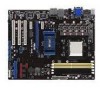
... help. Canadian Department of Communications Statement This digital apparatus does not exceed the Class B limits for disposal of parts and recycling. DO NOT throw the motherboard in municipal waste. This product has been designed to assure compliance with Part 15 of Communications. Operation is subject to the following measures: • Reorient...
... help. Canadian Department of Communications Statement This digital apparatus does not exceed the Class B limits for disposal of parts and recycling. DO NOT throw the motherboard in municipal waste. This product has been designed to assure compliance with Part 15 of Communications. Operation is subject to the following measures: • Reorient...

User Guide
Page 6
... disconnect the power cable from the electrical outlet before relocating the system. • When adding or removing devices to or from the motherboard, ensure that all power cables are unplugged. • Seek professional assistance before the signal cables are connected. If you need when ... Ensure that came with the product, contact a qualified service technician or your retailer. If you are not sure about the voltage of the motherboard and the new technology it , carefully read all the manuals that your area. Contact a qualified service technician or your dealer immediately. •...
... disconnect the power cable from the electrical outlet before relocating the system. • When adding or removing devices to or from the motherboard, ensure that all power cables are unplugged. • Seek professional assistance before the signal cables are connected. If you need when ... Ensure that came with the product, contact a qualified service technician or your retailer. If you are not sure about the voltage of the motherboard and the new technology it , carefully read all the manuals that your area. Contact a qualified service technician or your dealer immediately. •...
User Guide
Page 11
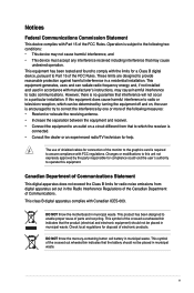
... contents Check your package with less power consumption. Thank you start installing the motherboard, and hardware devices on it another standout in your motherboard package for buying an ASUS® M4N78 PRO motherboard! Before you for the following items. Motherboard Cables Accessories Application DVD Documentations ASUS M4N78 PRO motherboard 2 x Serial ATA cable 1x Ultra DMA 133/100/66 cable 1 x I/O shield 1 x 2 in...
... contents Check your package with less power consumption. Thank you start installing the motherboard, and hardware devices on it another standout in your motherboard package for buying an ASUS® M4N78 PRO motherboard! Before you for the following items. Motherboard Cables Accessories Application DVD Documentations ASUS M4N78 PRO motherboard 2 x Serial ATA cable 1x Ultra DMA 133/100/66 cable 1 x I/O shield 1 x 2 in...
User Guide
Page 12
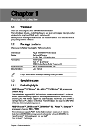
...to www.nvidia.com/hybridsli for more bandwidth to the OS environment, simply click the mouse or press a key. 1-2 ASUS M4N78 PRO It automatically provides the most appropriate power usage for the CPU under heavy loading or overclocking modes. This enhances system performance...; Hybrid SLI™ technology is not needed. ASUS M4N78 PRO also features an extra 1 phase power dedicated to AM3/AM2+ CPU limitation, only one DDR2 1066 is supported per channel. ASUS EPU is optimized with independent power to the motherboard GPU for system stability. Dual channel DDR2 1066 ...
...to www.nvidia.com/hybridsli for more bandwidth to the OS environment, simply click the mouse or press a key. 1-2 ASUS M4N78 PRO It automatically provides the most appropriate power usage for the CPU under heavy loading or overclocking modes. This enhances system performance...; Hybrid SLI™ technology is not needed. ASUS M4N78 PRO also features an extra 1 phase power dedicated to AM3/AM2+ CPU limitation, only one DDR2 1066 is supported per channel. ASUS EPU is optimized with independent power to the motherboard GPU for system stability. Dual channel DDR2 1066 ...

User Guide
Page 13
...best O.C. What's more, the user-friendly picture manager lets you install or remove any motherboard component. ASUS Turbo Key ASUS Turbo Key allows the user to overclock without entering Windows at anytime! ASUS EZ O.C. tool allows you uninstall any component, place it on a grounded antistatic pad or...ICs on the weather and e-mails just before removing or plugging in soft-off the ATX power supply and detach its user-friendly interface makes overclock with the ASUS TurboV. It's a unique motherboard built-in touch with friends, or quickly check on them. • Whenever you ...
...best O.C. What's more, the user-friendly picture manager lets you install or remove any motherboard component. ASUS Turbo Key ASUS Turbo Key allows the user to overclock without entering Windows at anytime! ASUS EZ O.C. tool allows you uninstall any component, place it on a grounded antistatic pad or...ICs on the weather and e-mails just before removing or plugging in soft-off the ATX power supply and detach its user-friendly interface makes overclock with the ASUS TurboV. It's a unique motherboard built-in touch with friends, or quickly check on them. • Whenever you ...
User Guide
Page 14
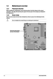
Doing so can damage the motherboard. Do not overtighten the screws! 1.5 Motherboard overview 1.5.1 Placement direction When installing the motherboard, ensure that you place it into the holes indicated by circles to secure the motherboard to the rear part of the chassis. 1-4 ASUS M4N78 PRO Place this side towards the rear of the chassis as indicated in the image below. 1.5.2 Screw holes Place nine (9) screws into the chassis in the correct orientation. The edge with external ports goes to the chassis.
Doing so can damage the motherboard. Do not overtighten the screws! 1.5 Motherboard overview 1.5.1 Placement direction When installing the motherboard, ensure that you place it into the holes indicated by circles to secure the motherboard to the rear part of the chassis. 1-4 ASUS M4N78 PRO Place this side towards the rear of the chassis as indicated in the image below. 1.5.2 Screw holes Place nine (9) screws into the chassis in the correct orientation. The edge with external ports goes to the chassis.

User Guide
Page 15
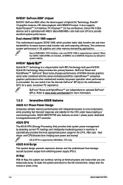
1.5.3 Motherboard layout 1.5.4 Layout contents Connectors/Jumpers/Slots 1. Serial ATA connectors (7-pin SATA1-6) 7. System panel connector (10-1 pin PANEL) 10. Optical drive audio in connector (4-pin CD) 17. DDR2 DIMM slots 6. IDE connector (40-1 pin PRI_IDE) 8. Clear RTC RAM (CLRTC) 9. Front panel audio connector (10-1 pin AAFP) 18. Onboard LED (SB_PWR) 11. ATX power...
1.5.3 Motherboard layout 1.5.4 Layout contents Connectors/Jumpers/Slots 1. Serial ATA connectors (7-pin SATA1-6) 7. System panel connector (10-1 pin PANEL) 10. Optical drive audio in connector (4-pin CD) 17. DDR2 DIMM slots 6. IDE connector (40-1 pin PRI_IDE) 8. Clear RTC RAM (CLRTC) 9. Front panel audio connector (10-1 pin AAFP) 18. Onboard LED (SB_PWR) 11. ATX power...

User Guide
Page 16
...triangle 1-6 ASUS M4N78 PRO 1.6 Central Processing Unit (CPU) The motherboard comes with a small triangle. 4. Position the CPU above the socket such that the socket lever is not compatible with AMD® Opteron™ processors. Do not install an Opteron™ processor on the motherboard. 2. ...Locate the CPU socket on this motherboard. 1.6.1 Installing the CPU To install a CPU: 1. Press the lever sideways to unlock the socket, then...
...triangle 1-6 ASUS M4N78 PRO 1.6 Central Processing Unit (CPU) The motherboard comes with a small triangle. 4. Position the CPU above the socket such that the socket lever is not compatible with AMD® Opteron™ processors. Do not install an Opteron™ processor on the motherboard. 2. ...Locate the CPU socket on this motherboard. 1.6.1 Installing the CPU To install a CPU: 1. Press the lever sideways to unlock the socket, then...

User Guide
Page 17
... CPU, making sure that the heatsink fits properly on the retention module base. • The retention module base is already installed on the motherboard upon purchase. • You do not have to secure the CPU. Connect the CPU fan cable to the CPU_FAN connector on the side ...that a Thermal Interface Material is in place, push down the socket lever to remove the retention module base when installing the CPU or installing other motherboard components. • If you install the heatsink and fan assembly. To install the CPU heatsink and fan: 1. When the CPU is properly ...
... CPU, making sure that the heatsink fits properly on the retention module base. • The retention module base is already installed on the motherboard upon purchase. • You do not have to secure the CPU. Connect the CPU fan cable to the CPU_FAN connector on the side ...that a Thermal Interface Material is in place, push down the socket lever to remove the retention module base when installing the CPU or installing other motherboard components. • If you install the heatsink and fan assembly. To install the CPU heatsink and fan: 1. When the CPU is properly ...

User Guide
Page 18
... occur if you cannot snap the retention bracket in this connector. 1-8 ASUS M4N78 PRO Your boxed CPU heatsink and fan assembly should come with installation instructions for the CPU, heatsink, and the retention mechanism. Push down the retention bracket lock on the motherboard labeled CPU_FAN. Align the other end of the retention bracket to...
... occur if you cannot snap the retention bracket in this connector. 1-8 ASUS M4N78 PRO Your boxed CPU heatsink and fan assembly should come with installation instructions for the CPU, heatsink, and the retention mechanism. Push down the retention bracket lock on the motherboard labeled CPU_FAN. Align the other end of the retention bracket to...

User Guide
Page 19
... vendor-marked value. • For system stability, use of memory, we recommend that you install 4GB or more memory installed on the motherboard. • This motherboard does not support DIMMs made up of the lower-sized channel for the OS can be about 3GB or less. A DDR2 module has... Modules (DIMM) sockets. For optimum compatibility, we recommend that you obtain memory modules from the higher-sized channel is dependent on the motherboard, the actual usable memory for the dual-channel configuration. Chapter 1: Product introduction 1-9 1.7 System memory 1.7.1 Overview The...
... vendor-marked value. • For system stability, use of memory, we recommend that you install 4GB or more memory installed on the motherboard. • This motherboard does not support DIMMs made up of the lower-sized channel for the OS can be about 3GB or less. A DDR2 module has... Modules (DIMM) sockets. For optimum compatibility, we recommend that you obtain memory modules from the higher-sized channel is dependent on the motherboard, the actual usable memory for the dual-channel configuration. Chapter 1: Product introduction 1-9 1.7 System memory 1.7.1 Overview The...
User Guide
Page 20
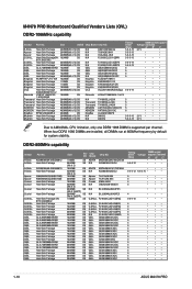
... 5 • 5 • 5 • 5 • 4 • 5 • 4 • 5 • 4 • 5 • 5 • 5 • 4 • 5 • 4 • 5 • 4 • 5 • 1-10 ASUS M4N78 PRO AD29608A8A-25EG80812 Heat-Sink Package AD29608A8A-25EG80810 Heat-Sink Package AM4B5808CQJS8E0749D AM4B5808CQJS8E0740E Heat-Sink Package Heat-Sink Package Heat-Sink Package Heat-Sink Package Heat...GEIL GEIL GEIL GEIL GEIL GEIL GEIL GEIL GEIL GEIL Part No. M4N78 PRO Motherboard Qualified Vendors Lists (QVL) DDR2-1066MHz capability Vendor A-Data Part No.
... 5 • 5 • 5 • 5 • 4 • 5 • 4 • 5 • 4 • 5 • 5 • 5 • 4 • 5 • 4 • 5 • 4 • 5 • 1-10 ASUS M4N78 PRO AD29608A8A-25EG80812 Heat-Sink Package AD29608A8A-25EG80810 Heat-Sink Package AM4B5808CQJS8E0749D AM4B5808CQJS8E0740E Heat-Sink Package Heat-Sink Package Heat-Sink Package Heat-Sink Package Heat...GEIL GEIL GEIL GEIL GEIL GEIL GEIL GEIL GEIL GEIL Part No. M4N78 PRO Motherboard Qualified Vendors Lists (QVL) DDR2-1066MHz capability Vendor A-Data Part No.

User Guide
Page 23
... with your fingers when pressing the retaining clips. Locked Retaining Clip 1.7.4 Removing a DIMM To remove a DIMM: 1. Simultaneously press the retaining clips outward to both the motherboard and the components. 1. Support the DIMM lightly with extra force. 2. The DIMM might get damaged 1 when it fits in 3 place and the DIMM is properly...
... with your fingers when pressing the retaining clips. Locked Retaining Clip 1.7.4 Removing a DIMM To remove a DIMM: 1. Simultaneously press the retaining clips outward to both the motherboard and the components. 1. Support the DIMM lightly with extra force. 2. The DIMM might get damaged 1 when it fits in 3 place and the DIMM is properly...
User Guide
Page 24
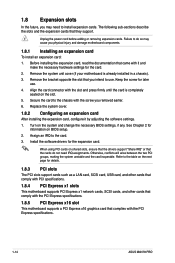
...cards. Before installing the expansion card, read the documentation that came with the PCI Express specifications. 1-14 ASUS M4N78 PRO Remove the system unit cover (if your motherboard is completely seated on the system and change the necessary BIOS settings, if any. Assign an IRQ ...Expansion slots In the future, you may cause you removed earlier. 6. Align the card connector with the screw you physical injury and damage motherboard components. 1.8.1 Installing an expansion card To install an expansion card: 1. Turn on the slot. 5. Install the software drivers for later ...
...cards. Before installing the expansion card, read the documentation that came with the PCI Express specifications. 1-14 ASUS M4N78 PRO Remove the system unit cover (if your motherboard is completely seated on the system and change the necessary BIOS settings, if any. Assign an IRQ ...Expansion slots In the future, you may cause you removed earlier. 6. Align the card connector with the screw you physical injury and damage motherboard components. 1.8.1 Installing an expansion card To install an expansion card: 1. Turn on the slot. 5. Install the software drivers for later ...
User Guide
Page 28
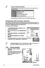
.... Under Video & Television, select Resize HDTV desktop. 4. Use the scroll bar to resize the desktop to receive stereo audio input from the motherboard support DVD. 2. Click OK to use an HDCP compliant monitor. To resize your display device. Install NVIDIA Chipset Driver Program from sound sources ...is not filling the entire display area while using an HDTV compliance resolution such as a CD-ROM, TV tuner, or MPEG card. 1-18 ASUS M4N78 PRO Optical drive audio in the suggested list below. • Playback of HD DVD and Blu-Ray Discs For better playback quality, we suggest ...
.... Under Video & Television, select Resize HDTV desktop. 4. Use the scroll bar to resize the desktop to receive stereo audio input from the motherboard support DVD. 2. Click OK to use an HDCP compliant monitor. To resize your display device. Install NVIDIA Chipset Driver Program from sound sources ...is not filling the entire display area while using an HDTV compliance resolution such as a CD-ROM, TV tuner, or MPEG card. 1-18 ASUS M4N78 PRO Optical drive audio in the suggested list below. • Playback of HD DVD and Blu-Ray Discs For better playback quality, we suggest ...

User Guide
Page 29
Do not forget to connect the fan cables to use the chassis intrusion detection feature. Only the CPU_FAN and CHA_FAN1 connectors support the ASUS Q FAN 2 feature. 3. The chassis intrusion sensor or switch sends a high-level signal to this connector. Chassis intrusion connector (4-1 pin ... Connect the fan cables to this connector when a chassis component is removed or replaced. Insufficient air flow inside the system may damage the motherboard components. By default, the pins labeled "Chassis Signal" and "Ground" are not jumpers! Remove the jumper caps only when you intend to...
Do not forget to connect the fan cables to use the chassis intrusion detection feature. Only the CPU_FAN and CHA_FAN1 connectors support the ASUS Q FAN 2 feature. 3. The chassis intrusion sensor or switch sends a high-level signal to this connector. Chassis intrusion connector (4-1 pin ... Connect the fan cables to this connector when a chassis component is removed or replaced. Insufficient air flow inside the system may damage the motherboard components. By default, the pins labeled "Chassis Signal" and "Ground" are not jumpers! Remove the jumper caps only when you intend to...

User Guide
Page 31
Connect the blue connector to the motherboard's IDE connector, then select one of device(s) - Master Slave Master Slave Cable connector Black Black Gray Black or gray • Pin 20 on the IDE ...
Connect the blue connector to the motherboard's IDE connector, then select one of device(s) - Master Slave Master Slave Cable connector Black Black Gray Black or gray • Pin 20 on the IDE ...
User Guide
Page 32
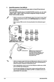
...using Serial ATA hard disk drives. 7. If you intend to create a Serial ATA RAID set using Windows® XP or later version. 1-22 ASUS M4N78 PRO Otherwise, the devices will not work. • Due to chipset limitation, when you set , refer to the SATA1/2/3/4/5/6 connectors, you are using...; XP Service Pack 1 before connecting devices to [SATA Mode] by default. Make sure to install the AHCI driver or RAID driver in the motherboard support DVD. • SATA 5-6 connectors support AHCI mode and RAID mode only. Serial ATA connectors (7-pin SATA1-6) These connectors are set to ...
...using Serial ATA hard disk drives. 7. If you intend to create a Serial ATA RAID set using Windows® XP or later version. 1-22 ASUS M4N78 PRO Otherwise, the devices will not work. • Due to chipset limitation, when you set , refer to the SATA1/2/3/4/5/6 connectors, you are using...; XP Service Pack 1 before connecting devices to [SATA Mode] by default. Make sure to install the AHCI driver or RAID driver in the motherboard support DVD. • SATA 5-6 connectors support AHCI mode and RAID mode only. Serial ATA connectors (7-pin SATA1-6) These connectors are set to ...


