
User Manual
Page 16
... or components. Failure to do so may cause severe damage to indicate that you install or remove any motherboard component. 1.4 Before you proceed Take note of the onboard LED. 1-4 ASUS M4N72-E This is a reminder that the system is ON, in sleep mode, or in any component, switch ...off mode. The illustration below shows the location of the following precautions before you install motherboard components or change any motherboard settings. • Unplug the power cord from the wall socket before removing or plugging in soft-off the ATX power supply and detach its power cord.
... or components. Failure to do so may cause severe damage to indicate that you install or remove any motherboard component. 1.4 Before you proceed Take note of the onboard LED. 1-4 ASUS M4N72-E This is a reminder that the system is ON, in sleep mode, or in any component, switch ...off mode. The illustration below shows the location of the following precautions before you install motherboard components or change any motherboard settings. • Unplug the power cord from the wall socket before removing or plugging in soft-off the ATX power supply and detach its power cord.

User Manual
Page 18
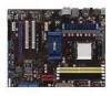
...ASUS M4N72-E USB device wake-up (3-pin USBPW1-4, USBPW7-10, USBPW1112) 4. CPU, Chassis and Power Fan connectors (4-pin CPU_FAN, 3-pin CHA_FAN1, 3-pin PWR_FAN) 6. DDR2 DIMM slots 7. Serial ATA connectors (7-pin SATA1-6) 8. CPU overvoltage setting (3-1 pin OV_CPU) 12. USB connectors (10-1 pin USB78, USB910, USB1112) 15. 1.5.3 Motherboard... layout 1.5.4 Layout contents Connectors/Jumpers/Slots 1. Serial port connector (10-1 pin COM1) 17. Optical drive audio in connector (4-pin CD) 20. System panel connector (20-8 pin PANEL) 13. ATX power connectors...
...ASUS M4N72-E USB device wake-up (3-pin USBPW1-4, USBPW7-10, USBPW1112) 4. CPU, Chassis and Power Fan connectors (4-pin CPU_FAN, 3-pin CHA_FAN1, 3-pin PWR_FAN) 6. DDR2 DIMM slots 7. Serial ATA connectors (7-pin SATA1-6) 8. CPU overvoltage setting (3-1 pin OV_CPU) 12. USB connectors (10-1 pin USB78, USB910, USB1112) 15. 1.5.3 Motherboard... layout 1.5.4 Layout contents Connectors/Jumpers/Slots 1. Serial port connector (10-1 pin COM1) 17. Optical drive audio in connector (4-pin CD) 20. System panel connector (20-8 pin PANEL) 13. ATX power connectors...
User Manual
Page 66
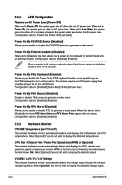
...detected temperatures. Select [Ignored] if you to enable or sisable the PCI/PCIE devices to display the detected voltage output. 2-22 ASUS M4N72-E This feature requires an ATX power supply that turns on the computer. CPU Fan / Chassis Fan / Power Fan Speed [xxxxRPM] or [Ignored] The onboard...: [Disabled] [Enabled] 2.6.6 Hardware Monitor CPU/MB Temperature [xxxºC/xxxºF] The onboard hardware monitor automatically detects and displays the motherboard and CPU temperatures. Select Ignored if you to disable the Power On by PS/2 keyboard function or set to Power Off, the system ...
...detected temperatures. Select [Ignored] if you to enable or sisable the PCI/PCIE devices to display the detected voltage output. 2-22 ASUS M4N72-E This feature requires an ATX power supply that turns on the computer. CPU Fan / Chassis Fan / Power Fan Speed [xxxxRPM] or [Ignored] The onboard...: [Disabled] [Enabled] 2.6.6 Hardware Monitor CPU/MB Temperature [xxxºC/xxxºF] The onboard hardware monitor automatically detects and displays the motherboard and CPU temperatures. Select Ignored if you to disable the Power On by PS/2 keyboard function or set to Power Off, the system ...


