

User Manual
Page 11
... the following items. Motherboard Cables Accessories Application DVD Documentation ASUS M4A78LT-M PLUS motherboard 2 x Serial ATA cables 1 x Ultra DMA 133/100/66 cable 1 x I/O shield ASUS motherboard Support DVD User Manual If any of ASUS quality motherboards! It features dual-channel DDR3 memory support ...and accelerates data transfer rate up to 5200MT/s via HyperTransport™ 3.0based system bus. ASUS M4A78LT-M PLUS 1-1 Thank you start installing the motherboard, and hardware devices on it another standout in the new 45nm manufacturing ...
... the following items. Motherboard Cables Accessories Application DVD Documentation ASUS M4A78LT-M PLUS motherboard 2 x Serial ATA cables 1 x Ultra DMA 133/100/66 cable 1 x I/O shield ASUS motherboard Support DVD User Manual If any of ASUS quality motherboards! It features dual-channel DDR3 memory support ...and accelerates data transfer rate up to 5200MT/s via HyperTransport™ 3.0based system bus. ASUS M4A78LT-M PLUS 1-1 Thank you start installing the motherboard, and hardware devices on it another standout in the new 45nm manufacturing ...

User Manual
Page 13
...the drives to update the BIOS from SATA HDDs, ODDs and USB drives. ASUS MyLogo2™ Turn your favorite photos into 256-color boot logos to turn the PC power button into an overclocking button. ASUS M4A78LT-M PLUS 1-3 When installing it on SATA HDDs, USB HDDs and flash drives with ...at least 1.2GB free disk space. ASUS Q-Fan ASUS Q-Fan technology intelligently adjusts the CPU fan speed according to system loading to ...
...the drives to update the BIOS from SATA HDDs, ODDs and USB drives. ASUS MyLogo2™ Turn your favorite photos into 256-color boot logos to turn the PC power button into an overclocking button. ASUS M4A78LT-M PLUS 1-3 When installing it on SATA HDDs, USB HDDs and flash drives with ...at least 1.2GB free disk space. ASUS Q-Fan ASUS Q-Fan technology intelligently adjusts the CPU fan speed according to system loading to ...
User Manual
Page 15
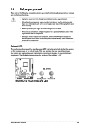
... OFF Standby Power Powered Off M4A78LT-M PLUS Onboard LED ASUS M4A78LT-M PLUS 1-5 Failure to do so may cause severe damage to indicate that the system is a reminder that lights up to the motherboard, peripherals, or components. Onboard ...
... OFF Standby Power Powered Off M4A78LT-M PLUS Onboard LED ASUS M4A78LT-M PLUS 1-5 Failure to do so may cause severe damage to indicate that the system is a reminder that lights up to the motherboard, peripherals, or components. Onboard ...
User Manual
Page 19
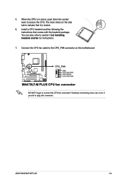
You can occur if you fail to section 1.6.2 Installing heatsink and fan for instructions. 7. ASUS M4A78LT-M PLUS 1-9 5. Install a CPU heatsink and fan following the instructions that it is in place, push down the socket lever to the CPU_FAN connector on the side... CPU fan connector! Hardware monitoring errors can also refer to plug this connector. The lever clicks on the motherboard. M4A78LT-M PLUS CPU_FAN GND CPU FAN PWR CPU FAN IN CPU FAN PWM M4A78LT-M PLUS CPU fan connector DO NOT forget to indicate that comes with the heatsink package. When the CPU is locked. 6....
You can occur if you fail to section 1.6.2 Installing heatsink and fan for instructions. 7. ASUS M4A78LT-M PLUS 1-9 5. Install a CPU heatsink and fan following the instructions that it is in place, push down the socket lever to the CPU_FAN connector on the side... CPU fan connector! Hardware monitoring errors can also refer to plug this connector. The lever clicks on the motherboard. M4A78LT-M PLUS CPU_FAN GND CPU FAN PWR CPU FAN IN CPU FAN PWM M4A78LT-M PLUS CPU fan connector DO NOT forget to indicate that comes with the heatsink package. When the CPU is locked. 6....

User Manual
Page 21
... the retention bracket in place. 4. Align the other end of the DDR3 DIMM sockets: DIMM_A1 DIMM_B1 Channel Channel A Channel B Sockets DIMM_A1 DIMM_B1 M4A78LT-M PLUS M4A78LT-M PLUS 240-pin DDR3 DIMM sockets ASUS M4A78LT-M PLUS 1-11 DO NOT forget to the retention module base. Push down the retention bracket lock on the motherboard labeled CPU_FAN. A clicking sound denotes...
... the retention bracket in place. 4. Align the other end of the DDR3 DIMM sockets: DIMM_A1 DIMM_B1 Channel Channel A Channel B Sockets DIMM_A1 DIMM_B1 M4A78LT-M PLUS M4A78LT-M PLUS 240-pin DDR3 DIMM sockets ASUS M4A78LT-M PLUS 1-11 DO NOT forget to the retention module base. Push down the retention bracket lock on the motherboard labeled CPU_FAN. A clicking sound denotes...
User Manual
Page 25
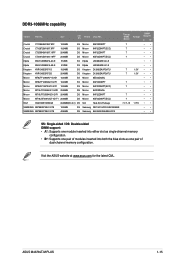
Size SS/ DS Brand Chip NO. Visit the ASUS website at www.asus.com for the latest QVL. ASUS M4A78LT-M PLUS 1-15 DDR3-1066MHz capability Vendor Part No. Crucial CT12864BA1067.8FF 1024MB SS Crucial CT12872BA1067.9FF 1024MB SS Crucial CT25664BA1067.16FF 2048MB DS Crucial CT25672BA1067.18FF ...
Size SS/ DS Brand Chip NO. Visit the ASUS website at www.asus.com for the latest QVL. ASUS M4A78LT-M PLUS 1-15 DDR3-1066MHz capability Vendor Part No. Crucial CT12864BA1067.8FF 1024MB SS Crucial CT12872BA1067.9FF 1024MB SS Crucial CT25664BA1067.16FF 2048MB DS Crucial CT25672BA1067.18FF ...

User Manual
Page 27
... the screw for the card. 2. Turn on the slot. 5. 1.8 Expansion slots In the future, you intend to use . 4. When using PCI cards on BIOS setup. 2. ASUS M4A78LT-M PLUS 1-17 The following sub‑sections describe the slots and the expansion cards that they support.
... the screw for the card. 2. Turn on the slot. 5. 1.8 Expansion slots In the future, you intend to use . 4. When using PCI cards on BIOS setup. 2. ASUS M4A78LT-M PLUS 1-17 The following sub‑sections describe the slots and the expansion cards that they support.

User Manual
Page 29
... low power mode) using the connected USB devices. USBPW1-4 12 23 +5V +5VSB (Default) USBPW5-10 M4A78LT-M PLUS 12 23 +5V +5VSB (Default) M4A78LT-M PLUS USB Device Wake Up 3. USB device wake-up (3-pin USBPW1-4, USBPW5-10) Set these jumpers to +5VSB... to wake up the computer from S3 and S4 sleep modes (no power to CPU, DRAM in slow refresh, power supply in the BIOS. KBPWR 12 23 +5V +5VSB (Default) M4A78LT-M PLUS M4A78LT-M PLUS Keyboard Power Setting ASUS M4A78LT-M PLUS...
... low power mode) using the connected USB devices. USBPW1-4 12 23 +5V +5VSB (Default) USBPW5-10 M4A78LT-M PLUS 12 23 +5V +5VSB (Default) M4A78LT-M PLUS USB Device Wake Up 3. USB device wake-up (3-pin USBPW1-4, USBPW5-10) Set these jumpers to +5VSB... to wake up the computer from S3 and S4 sleep modes (no power to CPU, DRAM in slow refresh, power supply in the BIOS. KBPWR 12 23 +5V +5VSB (Default) M4A78LT-M PLUS M4A78LT-M PLUS Keyboard Power Setting ASUS M4A78LT-M PLUS...
User Manual
Page 31
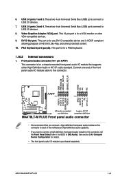
... AGND NC NC NC AAFP PIN 1 PIN 1 MIC2 MICPWR Line out_R NC Line out_L PORT1 L PORT1 R PORT2 R SENSE_SEND PORT2 L M4A78LT-M PLUS HD-audio-compliant Legacy AC'97 pin definition compliant definition M4A78LT-M PLUS Front panel audio connector • We recommend that supports either High Definition Audio or AC`97 audio standard. This 15... a VGA monitor or other protected content. 10. These two 4-pin Universal Serial Bus (USB) ports connect to USB 2.0 devices. 8. This port is purchased separately. ASUS M4A78LT-M PLUS 1-21 PS/2 Keyboard port (purple). 6. USB 2.0 ports 1 and 2.
... AGND NC NC NC AAFP PIN 1 PIN 1 MIC2 MICPWR Line out_R NC Line out_L PORT1 L PORT1 R PORT2 R SENSE_SEND PORT2 L M4A78LT-M PLUS HD-audio-compliant Legacy AC'97 pin definition compliant definition M4A78LT-M PLUS Front panel audio connector • We recommend that supports either High Definition Audio or AC`97 audio standard. This 15... a VGA monitor or other protected content. 10. These two 4-pin Universal Serial Bus (USB) ports connect to USB 2.0 devices. 8. This port is purchased separately. ASUS M4A78LT-M PLUS 1-21 PS/2 Keyboard port (purple). 6. USB 2.0 ports 1 and 2.

User Manual
Page 33
... select one of the following modes to PIN 1. If any device jumper is for Ultra DMA 133/100/66 IDE devices. M4A78LT-M PLUS IDE connector ASUS M4A78LT-M PLUS 1-23 This prevents incorrect insertion when you connect the IDE cable. • Use the 80-conductor IDE cable for Ultra DMA... 133/100/66 signal cable. PRI_IDE PIN1 M4A78LT-M PLUS NOTE:Orient the red markings on the Ultra DMA cable connector. 3. IDE connector (40-1...
... select one of the following modes to PIN 1. If any device jumper is for Ultra DMA 133/100/66 IDE devices. M4A78LT-M PLUS IDE connector ASUS M4A78LT-M PLUS 1-23 This prevents incorrect insertion when you connect the IDE cable. • Use the 80-conductor IDE cable for Ultra DMA... 133/100/66 signal cable. PRI_IDE PIN1 M4A78LT-M PLUS NOTE:Orient the red markings on the Ultra DMA cable connector. 3. IDE connector (40-1...
User Manual
Page 35
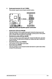
...disk drive activity LED (2-pin HDLED) This 2-pin connector is for the chassis-mounted reset button for the system power LED. ASUS M4A78LT-M PLUS 1-25 System panel connector (10-1 pin F_PANEL) This connector supports several chassis-mounted functions. Connect the chassis power LED cable to...this connector. Connect the HDD Activity LED cable to this connector. Ground Reset 5. PWR LED PWR BTN F_PANEL PIN 1 M4A78LT-M PLUS HD_LED RESET M4A78LT-M PLUS System panel connector • System power LED (2-pin PWRLED) This 2-pin connector is for system reboot without turning off ...
...disk drive activity LED (2-pin HDLED) This 2-pin connector is for the chassis-mounted reset button for the system power LED. ASUS M4A78LT-M PLUS 1-25 System panel connector (10-1 pin F_PANEL) This connector supports several chassis-mounted functions. Connect the chassis power LED cable to...this connector. Connect the HDD Activity LED cable to this connector. Ground Reset 5. PWR LED PWR BTN F_PANEL PIN 1 M4A78LT-M PLUS HD_LED RESET M4A78LT-M PLUS System panel connector • System power LED (2-pin PWRLED) This 2-pin connector is for system reboot without turning off ...

User Manual
Page 37
... purchased separately. 9. The S/PDIF module is VIA High Definition Audio (the name may be different based on the OS). 8. SPEAKER +5V GND GND Speaker Out M4A78LT-M PLUS PIN 1 M4A78LT-M PLUS Speaker Out Connector ASUS M4A78LT-M PLUS 1-27 Digital audio connector (4-1 pin SPDIF_OUT) This connector is for an additional Sony/Philips Digital Interface (S/PDIF) port.
... purchased separately. 9. The S/PDIF module is VIA High Definition Audio (the name may be different based on the OS). 8. SPEAKER +5V GND GND Speaker Out M4A78LT-M PLUS PIN 1 M4A78LT-M PLUS Speaker Out Connector ASUS M4A78LT-M PLUS 1-27 Digital audio connector (4-1 pin SPDIF_OUT) This connector is for an additional Sony/Philips Digital Interface (S/PDIF) port.

User Manual
Page 39
To run the DVD. ASUS M4A78LT-M PLUS 1-29 If Autorun is enabled in your computer, the DVD automatically...package contains the drivers, software applications, and utilities that you can install to maximize the features of ASUS motherboard. Click an icon to display Support DVD/ motherboard information Click an item to install If Autorun ... for updates. Double-click the ASSETUP.EXE to locate the file ASSETUP.EXE from the BIN folder. Visit the ASUS website at any time without notice. 1.11 Software support 1.11.1 Installing an operating system This motherboard supports Windows®...
To run the DVD. ASUS M4A78LT-M PLUS 1-29 If Autorun is enabled in your computer, the DVD automatically...package contains the drivers, software applications, and utilities that you can install to maximize the features of ASUS motherboard. Click an icon to display Support DVD/ motherboard information Click an item to install If Autorun ... for updates. Double-click the ASSETUP.EXE to locate the file ASSETUP.EXE from the BIN folder. Visit the ASUS website at any time without notice. 1.11 Software support 1.11.1 Installing an operating system This motherboard supports Windows®...

User Manual
Page 41
... in the future. From the dropdown list, select either through the Internet. b. The ASUS Update utility is a utility that comes with the motherboard package. ASUS M4A78LT-M PLUS 2-1 Copy the original motherboard BIOS using this utility. From the Windows® desktop, click Start > Programs > ASUS > ASUS Update > ASUS Update to restore the BIOS in Windows® environment. •...
... in the future. From the dropdown list, select either through the Internet. b. The ASUS Update utility is a utility that comes with the motherboard package. ASUS M4A78LT-M PLUS 2-1 Copy the original motherboard BIOS using this utility. From the Windows® desktop, click Start > Programs > ASUS > ASUS Update > ASUS Update to restore the BIOS in Windows® environment. •...

User Manual
Page 43
...The utility automatically checks the devices for details. For motherboards without a floppy connector, prepare a USB flash disk before using this utility. ASUS M4A78LT-M PLUS 2-3 Select the Load Setup Defaults item under the Exit menu. Doing so can restore a corrupted BIOS file using the motherboard support DVD.... Refer to ensure system compatibility and stability. Insert the support DVD to the optical drive or the removable device that ASUS CrashFree BIOS supports vary with motherboard models. Turn off the system after the utility completes the updating process and turn it...
...The utility automatically checks the devices for details. For motherboards without a floppy connector, prepare a USB flash disk before using this utility. ASUS M4A78LT-M PLUS 2-3 Select the Load Setup Defaults item under the Exit menu. Doing so can restore a corrupted BIOS file using the motherboard support DVD.... Refer to ensure system compatibility and stability. Insert the support DVD to the optical drive or the removable device that ASUS CrashFree BIOS supports vary with motherboard models. Turn off the system after the utility completes the updating process and turn it...
User Manual
Page 45
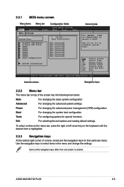
... a menu screen are the navigation keys for special functions Exit For selecting the exit options and loading default settings. Use the navigation keys to another. ASUS M4A78LT-M PLUS 2-5 To select an item on the menu bar, press the right or left arrow key on top of the navigation keys differ from one screen...
... a menu screen are the navigation keys for special functions Exit For selecting the exit options and loading default settings. Use the navigation keys to another. ASUS M4A78LT-M PLUS 2-5 To select an item on the menu bar, press the right or left arrow key on top of the navigation keys differ from one screen...

User Manual
Page 47
... a CD-ROM drive. Select [CDROM] if you an overview of IDE/SATA devices. Setting this item to [Auto] allows automatic selection of IDE/SATA drive. ASUS M4A78LT-M PLUS 2-7 The BIOS automatically detects the values opposite the dimmed items (Device, Vendor, Size, LBA Mode, Block Mode, PIO Mode, Async DMA, Ultra DMA, and SMART...
... a CD-ROM drive. Select [CDROM] if you an overview of IDE/SATA devices. Setting this item to [Auto] allows automatic selection of IDE/SATA drive. ASUS M4A78LT-M PLUS 2-7 The BIOS automatically detects the values opposite the dimmed items (Device, Vendor, Size, LBA Mode, Block Mode, PIO Mode, Async DMA, Ultra DMA, and SMART...
User Manual
Page 49
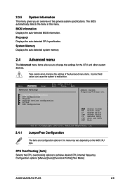
... depending on the AMD CPU type. Take caution when changing the settings of the general system specifications. Configuration options: [Manual] [Auto] [Overclock Profile] [Test Mode] ASUS M4A78LT-M PLUS 2-9 2.3.5 System Information This menu gives you to change the settings for the CPU and other system devices. BIOS Information Displays the auto-detected BIOS information...
... depending on the AMD CPU type. Take caution when changing the settings of the general system specifications. Configuration options: [Manual] [Auto] [Overclock Profile] [Test Mode] ASUS M4A78LT-M PLUS 2-9 2.3.5 System Information This menu gives you to change the settings for the CPU and other system devices. BIOS Information Displays the auto-detected BIOS information...
User Manual
Page 51
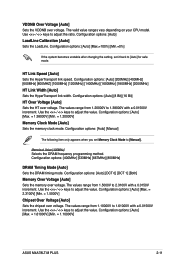
... values range from 1.10000V to 1.61000V with a 0.0150V increment. The values range from 1.5000V to adjust the ratio. Configuration options: [Auto] [Max. = 1.61000V] [Min. = 1.10000V] ASUS M4A78LT-M PLUS 2-11
... values range from 1.10000V to 1.61000V with a 0.0150V increment. The values range from 1.5000V to adjust the ratio. Configuration options: [Auto] [Max. = 1.61000V] [Min. = 1.10000V] ASUS M4A78LT-M PLUS 2-11

User Manual
Page 53
... only appears when you install an ATI graphics card into the PCIe x16 slot. Frame Buffer Location [Above 4G] Configuration options: [Below 4G] [Above 4G] ASUS M4A78LT-M PLUS 2-13 Configuration options: [Auto] [Always] Power Down Enable [Disabled] Allows you to set the ECC mode. Configuration options: [Disabled] [Enabled] ECC Configuration ECC Mode [Disabled...
... only appears when you install an ATI graphics card into the PCIe x16 slot. Frame Buffer Location [Above 4G] Configuration options: [Below 4G] [Above 4G] ASUS M4A78LT-M PLUS 2-13 Configuration options: [Auto] [Always] Power Down Enable [Disabled] Allows you to set the ECC mode. Configuration options: [Disabled] [Enabled] ECC Configuration ECC Mode [Disabled...

