User Manual
Page 11
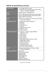
... (6 ports at mid-board, 6 ports at the back panel) 1 x PS/2 Keyboard / Mouse Combo port 1 x HDMI port 1 x DVI-D port 1 x LAN (RJ-45) port 1 x VGA port 1 x Optical S/PDIF_OUT port 6 x USB 2.0/1.1 ports 8-channel audio ports 3 x USB 2.0/1.1 connectors support additional 6 USB 2.0/1.1 ports 1 x IDE connector 1 x COM connector 1 x LPT connector 6 x SATA connectors 1 x High definition front panel audio connector 1 x System panel connector 1 x S/PDIF_OUT connector 1 x CPU fan connector 1 x Chassis fan connector 1 x 24-pin EATX power connector 1 x 4-pin ATX 12V power connector 8Mb Flash ROM, AMI BIOS...
... (6 ports at mid-board, 6 ports at the back panel) 1 x PS/2 Keyboard / Mouse Combo port 1 x HDMI port 1 x DVI-D port 1 x LAN (RJ-45) port 1 x VGA port 1 x Optical S/PDIF_OUT port 6 x USB 2.0/1.1 ports 8-channel audio ports 3 x USB 2.0/1.1 connectors support additional 6 USB 2.0/1.1 ports 1 x IDE connector 1 x COM connector 1 x LPT connector 6 x SATA connectors 1 x High definition front panel audio connector 1 x System panel connector 1 x S/PDIF_OUT connector 1 x CPU fan connector 1 x Chassis fan connector 1 x 24-pin EATX power connector 1 x 4-pin ATX 12V power connector 8Mb Flash ROM, AMI BIOS...

User Manual
Page 15
... configuration. • ASUS Express Gate supports file uploading from switching power supply. ASUS Turbo Key ASUS Turbo Key allows you quick access to USB drives only. • ASUS Express Gate complies with at least 1.2GB free disk space. Gigabit LAN solution The onboard LAN controller is enhanced with an ACPI management function to the motherboard USB port before turning on the computer. • The actual boot time depends on SATA HDDs, USB HDDs and flash drives with the OpenGL standard. When installing it on USB HDDs or flash drives, connect the drives...
... configuration. • ASUS Express Gate supports file uploading from switching power supply. ASUS Turbo Key ASUS Turbo Key allows you quick access to USB drives only. • ASUS Express Gate complies with at least 1.2GB free disk space. Gigabit LAN solution The onboard LAN controller is enhanced with an ACPI management function to the motherboard USB port before turning on the computer. • The actual boot time depends on SATA HDDs, USB HDDs and flash drives with the OpenGL standard. When installing it on USB HDDs or flash drives, connect the drives...
User Manual
Page 19
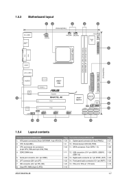
.... Front panel audio connector (10-1 pin AAFP) 1-25 15. CPU Socket AM2+ 3. LPT connector (26-1 pin LPT) 7. System panel connector (20-8 pin PANEL) 10. SATA connectors (7-pin SATA1 - 6) 1-11 12. Digital audio connector (4-1 pin SPDIF_OUT) 1-22 14. ATX power connectors (24-pin EATXPWR, 4-pin ATX12V) 2. Serial port connector (10-1 pin COM1) 6. CPU and chassis fan connectors (4-pin CPU_FAN and 3-pin CHA_FAN) 4. PCIe x16 / PCIe x1 / PCI slots 1-19 Page 1-27 1-5 1-26 1-28 1-29 1-23 1-18 ASUS M4A78L-M 1-7 Clear RTC RAM (3-pin CLRTC) Page 1-24 1-8 1-23 Connectors/Jumpers/Slots/LED...
.... Front panel audio connector (10-1 pin AAFP) 1-25 15. CPU Socket AM2+ 3. LPT connector (26-1 pin LPT) 7. System panel connector (20-8 pin PANEL) 10. SATA connectors (7-pin SATA1 - 6) 1-11 12. Digital audio connector (4-1 pin SPDIF_OUT) 1-22 14. ATX power connectors (24-pin EATXPWR, 4-pin ATX12V) 2. Serial port connector (10-1 pin COM1) 6. CPU and chassis fan connectors (4-pin CPU_FAN and 3-pin CHA_FAN) 4. PCIe x16 / PCIe x1 / PCI slots 1-19 Page 1-27 1-5 1-26 1-28 1-29 1-23 1-18 ASUS M4A78L-M 1-7 Clear RTC RAM (3-pin CLRTC) Page 1-24 1-8 1-23 Connectors/Jumpers/Slots/LED...
User Manual
Page 30
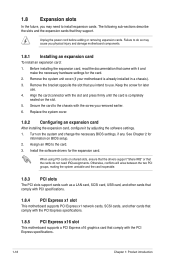
... motherboard supports PCI Express x1 network cards, SCSI cards, and other cards that comply with the PCI Express specifications. 1.8.5 PCI Express x16 slot This motherboard supports a PCI Express x16 graphics card that came with the slot and press firmly until the card is already installed in a chassis). 3. Unplug the power cord before adding or removing expansion cards. Secure the card to use . 4. Failure to do not need to the card. 3. Keep the screw for information on the system and change the necessary BIOS settings...
... motherboard supports PCI Express x1 network cards, SCSI cards, and other cards that comply with the PCI Express specifications. 1.8.5 PCI Express x16 slot This motherboard supports a PCI Express x16 graphics card that came with the slot and press firmly until the card is already installed in a chassis). 3. Unplug the power cord before adding or removing expansion cards. Secure the card to use . 4. Failure to do not need to the card. 3. Keep the screw for information on the system and change the necessary BIOS settings...

User Manual
Page 33
... 2-channel Line In Line Out Mic In - - - 4-channel Line In Front Speaker Out Mic In - USB 2.0 ports 1 and 2. USB 2.0 ports 3 and 4. ASUS M4A78L-M 1-21 DVI-D port. Dual display output support • This table indicates that whether the following dual display outputs are supported on the OS). Go to Start > Control Panel > Sounds and Audio Devices > Sound Playback to USB 2.0 devices. 12. These two 4-pin Universal Serial Bus (USB) ports connect to configure the settings. 11. These two 4-pin Universal Serial Bus (USB) ports connect to the D-Sub port has display. HDMI port.
... 2-channel Line In Line Out Mic In - - - 4-channel Line In Front Speaker Out Mic In - USB 2.0 ports 1 and 2. USB 2.0 ports 3 and 4. ASUS M4A78L-M 1-21 DVI-D port. Dual display output support • This table indicates that whether the following dual display outputs are supported on the OS). Go to Start > Control Panel > Sounds and Audio Devices > Sound Playback to USB 2.0 devices. 12. These two 4-pin Universal Serial Bus (USB) ports connect to configure the settings. 11. These two 4-pin Universal Serial Bus (USB) ports connect to the D-Sub port has display. HDMI port.
User Manual
Page 39
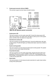
... speaker allows you turn on the BIOS settings. PWR Ground Reset Ground M4A78L-M IDE_LED PWRSW RESET * Requires an ATX power supply M4A78L-M System panel connector • System power LED This 2-pin connector is for the HDD Activity LED. Connect the HDD Activity LED cable to this connector. Pressing the power button turns the system ON or puts the system in SLEEP or SOFT-OFF mode depending on the system power, and blinks when the system is in sleep mode. • Hard disk drive activity LED This 2-pin connector...
... speaker allows you turn on the BIOS settings. PWR Ground Reset Ground M4A78L-M IDE_LED PWRSW RESET * Requires an ATX power supply M4A78L-M System panel connector • System power LED This 2-pin connector is for the HDD Activity LED. Connect the HDD Activity LED cable to this connector. Pressing the power button turns the system ON or puts the system in SLEEP or SOFT-OFF mode depending on the system power, and blinks when the system is in sleep mode. • Hard disk drive activity LED This 2-pin connector...

User Manual
Page 41
... system chassis. Serial port connector (10-1 pin COM1) The connector is purchased separately. 10. COM1 PIN 1 M4A78L-M M4A78L-M Serial port (COM1) connector ASUS M4A78L-M 1-29 9. The serial port bracket (COM1) is VIA High Definition Audio (the name may be different based on the OS). Go to Start > Control Panel > Sounds and Audio Devices > Sound Playback to a slot opening at the back of Sound playback is purchased separately. Connect the serial port module cable to the connector, then install the module to configure the setting. Digital audio connector (4-1 pin...
... system chassis. Serial port connector (10-1 pin COM1) The connector is purchased separately. 10. COM1 PIN 1 M4A78L-M M4A78L-M Serial port (COM1) connector ASUS M4A78L-M 1-29 9. The serial port bracket (COM1) is VIA High Definition Audio (the name may be different based on the OS). Go to Start > Control Panel > Sounds and Audio Devices > Sound Playback to a slot opening at the back of Sound playback is purchased separately. Connect the serial port module cable to the connector, then install the module to configure the setting. Digital audio connector (4-1 pin...
User Manual
Page 42
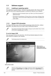
... display Support DVD/ motherboard information Click an item to change at www.asus.com for updates. The contents of the Support DVD are subject to install If Autorun is for better compatibility and system stability. 1.11.2 Support DVD information The Support DVD that comes with the motherboard package contains the drivers, software applications, and utilities that you install Windows® XP Service Pack 3 or later versions / Windows® Vista Service Pack 1 or later versions before installing the drivers...
... display Support DVD/ motherboard information Click an item to change at www.asus.com for updates. The contents of the Support DVD are subject to install If Autorun is for better compatibility and system stability. 1.11.2 Support DVD information The Support DVD that comes with the motherboard package contains the drivers, software applications, and utilities that you install Windows® XP Service Pack 3 or later versions / Windows® Vista Service Pack 1 or later versions before installing the drivers...
User Manual
Page 43
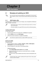
...click ASUS Update. 3. ASUS M4A78L-M 2-1 Updating the BIOS To update the BIOS: 1. Follow the onscreen instructions to launch the ASUS Update utility. 2. b. From the dropdown list, select either through the Internet. Always update the utility to avail all Windows® applications before you to avoid network traffic, or click Auto Select then click Next. From the Windows® desktop, click Start > Programs > ASUS > ASUS Update > ASUS Update to complete the installation. Copy the original motherboard BIOS using this utility. The Drivers menu appears...
...click ASUS Update. 3. ASUS M4A78L-M 2-1 Updating the BIOS To update the BIOS: 1. Follow the onscreen instructions to launch the ASUS Update utility. 2. b. From the dropdown list, select either through the Internet. Always update the utility to avail all Windows® applications before you to avoid network traffic, or click Auto Select then click Next. From the Windows® desktop, click Start > Programs > ASUS > ASUS Update > ASUS Update to complete the installation. Copy the original motherboard BIOS using this utility. The Drivers menu appears...
User Manual
Page 44
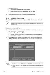
.... 2.1.2 ASUS EZ Flash 2 utility The ASUS EZ Flash 2 feature allows you start using this utility, download the latest BIOS file from a file, then click Next. ASUSTek EZ Flash 2 BIOS ROM Utility V3.36 FLASH TYPE: MXIC 25L8005 Current ROM BOARD: M4A78L-M VER: 0204 (H:00 B:02) DATE: 09/02/2009 Update ROM BOARD: Unknown VER: Unknown DATE: Unknown PATH: C:\ C: Note [Enter] Select or Load [Tab] Switch [Up/Down/Home/End] Move [B] Backup [V] Drive Info [ESC] Exit • This function supports USB flash disks...
.... 2.1.2 ASUS EZ Flash 2 utility The ASUS EZ Flash 2 feature allows you start using this utility, download the latest BIOS file from a file, then click Next. ASUSTek EZ Flash 2 BIOS ROM Utility V3.36 FLASH TYPE: MXIC 25L8005 Current ROM BOARD: M4A78L-M VER: 0204 (H:00 B:02) DATE: 09/02/2009 Update ROM BOARD: Unknown VER: Unknown DATE: Unknown PATH: C:\ C: Note [Enter] Select or Load [Tab] Switch [Up/Down/Home/End] Move [B] Backup [V] Drive Info [ESC] Exit • This function supports USB flash disks...
User Manual
Page 45
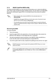
... BIOS default settings to section 2.8 Exit menu for the BIOS file. Refer to ensure system compatibility and stability. You can cause system boot failure! For motherboards without a floppy connector, prepare a USB flash disk before using this utility. Doing so can restore a corrupted BIOS file using the motherboard support DVD or a removable device that contains the BIOS file to the USB port or to the floppy disk drive, if supported. 3. ASUS M4A78L-M 2-3 The utility automatically checks the devices for details. When the BIOS file is an auto recovery tool that ASUS CrashFree BIOS...
... BIOS default settings to section 2.8 Exit menu for the BIOS file. Refer to ensure system compatibility and stability. You can cause system boot failure! For motherboards without a floppy connector, prepare a USB flash disk before using this utility. Doing so can restore a corrupted BIOS file using the motherboard support DVD or a removable device that contains the BIOS file to the USB port or to the floppy disk drive, if supported. 3. ASUS M4A78L-M 2-3 The utility automatically checks the devices for details. When the BIOS file is an auto recovery tool that ASUS CrashFree BIOS...
User Manual
Page 48
... Change Freq. : Yes uCode Patch Level : 0x1000086 This option should remain disabled for testing purpose. A configurable field is enclosed in brackets, and is not user-configurable. BIOS SETUP UTILITY Advanced CPU Configuration Module Version: 13.58 AGESA Version: 3.5.3.1 AMD Phenom(tm) II X4 945 Processor Revision: C2 Cache L1: 512KB Cache L2: 2048KB Cache L3: 6MB Options Speed : 3000MHz, NB Cl Disabled HT Frequency : 2000MHz Enabled Able to display a pop-up window...
... Change Freq. : Yes uCode Patch Level : 0x1000086 This option should remain disabled for testing purpose. A configurable field is enclosed in brackets, and is not user-configurable. BIOS SETUP UTILITY Advanced CPU Configuration Module Version: 13.58 AGESA Version: 3.5.3.1 AMD Phenom(tm) II X4 945 Processor Revision: C2 Cache L1: 512KB Cache L2: 2048KB Cache L3: 6MB Options Speed : 3000MHz, NB Cl Disabled HT Frequency : 2000MHz Enabled Able to display a pop-up window...
User Manual
Page 50
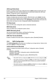
... [Enabled] 2.3.4 SATA Configuration The SATA Configuration menu allows you can be configured as [IDE]. • When SATA 1/2/3/4/5/6 are configured as [AHCI], only SATA 1/2/3/4 can access the devices on SATA 5/6 before entering OS. 2-8 Chapter 2: BIOS information Configuration options: [IDE] [RAID] [AHCI] SATA Port5 - Setting this item to [Auto] enables the LBA mode if the device supports this item is set to [Disabled], the data transfer from and to display the submenu. Configuration options: [Disabled] [Auto] PIO Mode [Auto] Selects the PIO mode. Port4 [IDE] Configures SATA...
... [Enabled] 2.3.4 SATA Configuration The SATA Configuration menu allows you can be configured as [IDE]. • When SATA 1/2/3/4/5/6 are configured as [AHCI], only SATA 1/2/3/4 can access the devices on SATA 5/6 before entering OS. 2-8 Chapter 2: BIOS information Configuration options: [IDE] [RAID] [AHCI] SATA Port5 - Setting this item to [Auto] enables the LBA mode if the device supports this item is set to [Disabled], the data transfer from and to display the submenu. Configuration options: [Disabled] [Auto] PIO Mode [Auto] Selects the PIO mode. Port4 [IDE] Configures SATA...

User Manual
Page 51
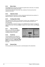
... BIOS SETUP UTILITY Boot Tools Exit JumperFree Configuration CPU Configuration Chipset Onboard Devices Configuration PCIPnP USB Configuration Adjust System Frequency/Voltage etc. Select Screen Select Item +- CPU OverClocking [Auto] Selects the CPU overclocking options to malfunction. Configuration options: [Auto] [Manual] [Overclock Profile] [Test Mode] ASUS M4A78L-M 2-9 Take caution when changing the settings of the general system specifications. 2.3.5 System Information This menu gives you to change the settings for the CPU and other system devices. System Memory Displays...
... BIOS SETUP UTILITY Boot Tools Exit JumperFree Configuration CPU Configuration Chipset Onboard Devices Configuration PCIPnP USB Configuration Adjust System Frequency/Voltage etc. Select Screen Select Item +- CPU OverClocking [Auto] Selects the CPU overclocking options to malfunction. Configuration options: [Auto] [Manual] [Overclock Profile] [Test Mode] ASUS M4A78L-M 2-9 Take caution when changing the settings of the general system specifications. 2.3.5 System Information This menu gives you to change the settings for the CPU and other system devices. System Memory Displays...
User Manual
Page 52
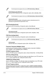
... GPU overclocking. Configuration options: [Min.=150] [Max.=1500] PCIE Overclocking [Auto] Configures the PCIE overclocking. The following item only appears when you set GPU Overclocking to [Manual]. GPU Engine Clock [500] Sets the GPU Engine Clock. Configuration options: [Auto] HT Link Frequency [Auto] Sets the HyperTransport link speed. Configuration options: [Min.=100] [Max.=150] Processor Frequency Multiplier [Auto] Sets the processor frequency multiplier. The valid value ranges vary depending on your CPU model. Configuration options: [Auto] VDDNB Over Voltage [Auto] Sets the...
... GPU overclocking. Configuration options: [Min.=150] [Max.=1500] PCIE Overclocking [Auto] Configures the PCIE overclocking. The following item only appears when you set GPU Overclocking to [Manual]. GPU Engine Clock [500] Sets the GPU Engine Clock. Configuration options: [Auto] HT Link Frequency [Auto] Sets the HyperTransport link speed. Configuration options: [Min.=100] [Max.=150] Processor Frequency Multiplier [Auto] Sets the processor frequency multiplier. The valid value ranges vary depending on your CPU model. Configuration options: [Auto] VDDNB Over Voltage [Auto] Sets the...

User Manual
Page 54
... Configuration Memory Configuration Bank Interleaving [Auto] Allows you to [Per Core], the processor's overclocking capability is set to decrease power consumption. Configuration options: [Disabled] [Enabled] 2-12 Chapter 2: BIOS information When this item is enabled, the CPU core frequency and voltage will be reduced during C3 and Alt VID. Configuration options: [Disabled] [Enabled] Memory Hole Remapping [Enabled] Enables or disables memory remapping around memory hole. Configuration options: [Disabled] [Enabled] DCT Unganged Mode [Always] Selects the unganged DRAM mode (64-bit...
... Configuration Memory Configuration Bank Interleaving [Auto] Allows you to [Per Core], the processor's overclocking capability is set to decrease power consumption. Configuration options: [Disabled] [Enabled] 2-12 Chapter 2: BIOS information When this item is enabled, the CPU core frequency and voltage will be reduced during C3 and Alt VID. Configuration options: [Disabled] [Enabled] Memory Hole Remapping [Enabled] Enables or disables memory remapping around memory hole. Configuration options: [Disabled] [Enabled] DCT Unganged Mode [Always] Selects the unganged DRAM mode (64-bit...

User Manual
Page 56
... options: [Enabled] [Disabled] Front Panel Select [HD Audio] Configuration options: [HD Audio] [AC97] OnBoard LAN Controller [Enabled] Configuration options: [Enabled] [Disabled] OnBoard LAN Boot ROM [Disabled] Configuration options: [Disabled] [Enabled] 2.4.5 PCIPnP The PCI PnP menu items allow you to malfunction. Take caution when changing the settings of the PCI PnP menu items. Incorrect field values can cause the system to select the Parallel Port mode. Configuration options: [Disabled] [378] [278] [3BC] Parallel Port Mode [Normal] Allows you to [No], BIOS configures all the devices...
... options: [Enabled] [Disabled] Front Panel Select [HD Audio] Configuration options: [HD Audio] [AC97] OnBoard LAN Controller [Enabled] Configuration options: [Enabled] [Disabled] OnBoard LAN Boot ROM [Disabled] Configuration options: [Disabled] [Enabled] 2.4.5 PCIPnP The PCI PnP menu items allow you to malfunction. Take caution when changing the settings of the PCI PnP menu items. Incorrect field values can cause the system to select the Parallel Port mode. Configuration options: [Disabled] [378] [278] [3BC] Parallel Port Mode [Normal] Allows you to [No], BIOS configures all the devices...

User Manual
Page 57
... storage devices, including USB flash drives and USB hard drives. Configuration options: [Disabled] [Enabled] Legacy USB Support [Auto] Allows you to change the USB-related features. If detected, the USB controller legacy mode is plugged in HiSpeed (480Mbps) or Full Speed (12Mbps). The Module Version and USB Devices Enabled items show the auto-detected values. Configuration options: [Disabled] [Enabled] [Auto] USB 2.0 Controller Mode [HiSpeed] Allows you to display the configuration options. Configuration options: [Auto] [Floppy] [Forced FDD] [Hard Disk] [CDROM] ASUS...
... storage devices, including USB flash drives and USB hard drives. Configuration options: [Disabled] [Enabled] Legacy USB Support [Auto] Allows you to change the USB-related features. If detected, the USB controller legacy mode is plugged in HiSpeed (480Mbps) or Full Speed (12Mbps). The Module Version and USB Devices Enabled items show the auto-detected values. Configuration options: [Disabled] [Enabled] [Auto] USB 2.0 Controller Mode [HiSpeed] Allows you to display the configuration options. Configuration options: [Auto] [Floppy] [Forced FDD] [Hard Disk] [CDROM] ASUS...

User Manual
Page 58
...Support [Enabled] Allows you to enable or disable the Advanced Configuration and Power Interface (ACPI) support in the RSDT pointer list. Configuration options: [Disabled] [Enabled] Power on From S5 By Ring [Disabled] Enables or disables ring to generate a wake event. Configuration options: [Power Off] [Power On] [Last State] Power on after an AC power loss. Main Advanced Power BIOS SETUP UTILITY Boot Tools Exit Power Settings Suspend Mode [Auto] ACPI 2.0 Support [Enabled] ACPI APIC Support [Enabled] APM Configuration HW Monitor Configuration Anti Surge Support [Enabled...
...Support [Enabled] Allows you to enable or disable the Advanced Configuration and Power Interface (ACPI) support in the RSDT pointer list. Configuration options: [Disabled] [Enabled] Power on From S5 By Ring [Disabled] Enables or disables ring to generate a wake event. Configuration options: [Power Off] [Power On] [Last State] Power on after an AC power loss. Main Advanced Power BIOS SETUP UTILITY Boot Tools Exit Power Settings Suspend Mode [Auto] ACPI 2.0 Support [Enabled] ACPI APIC Support [Enabled] APM Configuration HW Monitor Configuration Anti Surge Support [Enabled...

User Manual
Page 59
... to the motherboard, the field shows N/A. ASUS M4A78L-M 2-17 If the fan is not connected to be displayed. Main Advanced Power BIOS SETUP UTILITY Boot Tools Exit Boot Settings Boot Device Priority Boot Settings Configuration Security Specifies the Boot Device Priority sequence. Configuration options: [Disabled] [Enabled] Chassis Fan Speed [N/A], [xxxxRPM], or [Ignored] The onboard hardware monitor automatically detects and displays the Chassis fan speeds in rotations per minute (RPM). Select [gnored] if you do not wish to generate a wake event. Select Screen Select Item Enter Go...
... to the motherboard, the field shows N/A. ASUS M4A78L-M 2-17 If the fan is not connected to be displayed. Main Advanced Power BIOS SETUP UTILITY Boot Tools Exit Boot Settings Boot Device Priority Boot Settings Configuration Security Specifies the Boot Device Priority sequence. Configuration options: [Disabled] [Enabled] Chassis Fan Speed [N/A], [xxxxRPM], or [Ignored] The onboard hardware monitor automatically detects and displays the Chassis fan speeds in rotations per minute (RPM). Select [gnored] if you do not wish to generate a wake event. Select Screen Select Item Enter Go...


