
User Manual
Page 1
Motherboard
Motherboard

User Manual
Page 1
M4A78 PLUS Motherboard
M4A78 PLUS Motherboard
User Manual
Page 3
Contents Notices...vi Safety information vii About this guide vii M4A78 PLUS specifications summary ix Chapter 1 Product introduction 1.1 Welcome 1-1 1.2 Package contents 1-1 1.3 Special features 1-1 1.3.1 Product highlights 1-1 1.3.2 Innovative ASUS features 1-4 1.4 Before you proceed 1-6 Onboard LED 1-6 1.5 Motherboard overview 1-7 1.5.1 Placement direction 1-7 1.5.2 Screw holes 1-7 1.5.3 Motherboard layout 1-8 1.5.4 Layout contents 1-8 1.6 Central Processing Unit (CPU 1-9 1.6.1 Installing the CPU 1-9 1.6.2 Installing the heatsink and fan 1-11...
Contents Notices...vi Safety information vii About this guide vii M4A78 PLUS specifications summary ix Chapter 1 Product introduction 1.1 Welcome 1-1 1.2 Package contents 1-1 1.3 Special features 1-1 1.3.1 Product highlights 1-1 1.3.2 Innovative ASUS features 1-4 1.4 Before you proceed 1-6 Onboard LED 1-6 1.5 Motherboard overview 1-7 1.5.1 Placement direction 1-7 1.5.2 Screw holes 1-7 1.5.3 Motherboard layout 1-8 1.5.4 Layout contents 1-8 1.6 Central Processing Unit (CPU 1-9 1.6.1 Installing the CPU 1-9 1.6.2 Installing the heatsink and fan 1-11...
User Manual
Page 6
... that to an outlet on , the user is encouraged to try to correct the interference by the party responsible for help. DO NOT throw the motherboard in municipal waste. Changes or modifications to this unit not expressly approved by one or more of the following two conditions: • This device may...
... that to an outlet on , the user is encouraged to try to correct the interference by the party responsible for help. DO NOT throw the motherboard in municipal waste. Changes or modifications to this unit not expressly approved by one or more of the following two conditions: • This device may...

User Manual
Page 7
...• Avoid dust, humidity, and temperature extremes. If you add a device. • Before connecting or removing signal cables from the motherboard, ensure that all power cables are not damaged. About this guide is set to the correct voltage in any damage, contact your power... If you are using an adapter or extension cord. Contact a qualified service technician or your retailer. Operation safety • Before installing the motherboard and adding devices on it may become wet. • Place the product on a stable surface. • If you encounter technical problems ...
...• Avoid dust, humidity, and temperature extremes. If you add a device. • Before connecting or removing signal cables from the motherboard, ensure that all power cables are not damaged. About this guide is set to the correct voltage in any damage, contact your power... If you are using an adapter or extension cord. Contact a qualified service technician or your retailer. Operation safety • Before installing the motherboard and adding devices on it may become wet. • Place the product on a stable surface. • If you encounter technical problems ...

User Manual
Page 11
... up to 5200MT/s via HyperTransport™ 3.0 based system bus. The motherboard delivers a host of new features and latest technologies, making it , check the items in the new 45nm manufacturing process. Before you for the following items. Motherboard Cables Accessories Application DVD Documentations ASUS M4A78 PLUS motherboard 2 x Serial ATA cables 1 x 2in1 SATA power cable 1 x Ultra DMA 133...
... up to 5200MT/s via HyperTransport™ 3.0 based system bus. The motherboard delivers a host of new features and latest technologies, making it , check the items in the new 45nm manufacturing process. Before you for the following items. Motherboard Cables Accessories Application DVD Documentations ASUS M4A78 PLUS motherboard 2 x Serial ATA cables 1 x 2in1 SATA power cable 1 x Ultra DMA 133...

User Manual
Page 12
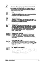
... performance in 3D graphics and other memory demanding applications. 1-2 ASUS M4A78 PLUS High Definition Audio Enjoy high-end sound quality on your CrossFireX system. AMD® Phenom™ X4 / Phenom™ X3 / Athlon™ X2 / Athlon™ / Sempron™ processors (socket AM2+/AM2) This motherboard supports AMD® Socket AM2+ multi-core processors. HyperTransportTM...
... performance in 3D graphics and other memory demanding applications. 1-2 ASUS M4A78 PLUS High Definition Audio Enjoy high-end sound quality on your CrossFireX system. AMD® Phenom™ X4 / Phenom™ X3 / Athlon™ X2 / Athlon™ / Sempron™ processors (socket AM2+/AM2) This motherboard supports AMD® Socket AM2+ multi-core processors. HyperTransportTM...
User Manual
Page 13
... supported by default for system stability. Backwards compatible with an ACPI management function to the ASUS website at 800MHz frequency by AM2+/AM3 CPU only. Easily back up to 40 times faster at the back I /O port This motherboard provides convenient connectivity to AM2+/AM3 CPU limitation, only one DDR2 1066 DIMM is...
... supported by default for system stability. Backwards compatible with an ACPI management function to the ASUS website at 800MHz frequency by AM2+/AM3 CPU only. Easily back up to 40 times faster at the back I /O port This motherboard provides convenient connectivity to AM2+/AM3 CPU limitation, only one DDR2 1066 DIMM is...

User Manual
Page 14
... your system. After the easy setup, Turbo Key boosts performances without entering Windows® or hard devices. ASUS EZ Flash 2 ASUS EZ Flash 2 is a utility that allows you to update the BIOS without using the bundled support DVD,...ASUS CrashFree BIOS 3 ASUS CrashFree BIOS 3 is built into the motherboard, so you to hardware configuration and product models. • For SSD version, Express Gate is an auto-recovery tool that contains the BIOS file. It automatically provides the most appropriate power usage to ensure quiet, cool, and efficient operation. 1-4 ASUS M4A78 PLUS...
... your system. After the easy setup, Turbo Key boosts performances without entering Windows® or hard devices. ASUS EZ Flash 2 ASUS EZ Flash 2 is a utility that allows you to update the BIOS without using the bundled support DVD,...ASUS CrashFree BIOS 3 ASUS CrashFree BIOS 3 is built into the motherboard, so you to hardware configuration and product models. • For SSD version, Express Gate is an auto-recovery tool that contains the BIOS file. It automatically provides the most appropriate power usage to ensure quiet, cool, and efficient operation. 1-4 ASUS M4A78 PLUS...
User Manual
Page 15
...at minimum power and noise when user is in line with the European Union's Restriction on the environment. Chapter 1: Product introduction 1-5 ASUS AI Nap Minimize noise and power consumption when temporarily away! It keeps downloading files or running applications in few seconds. C.P.R. eliminates ... wake up the system in quietest state while you can instantly snooze your PC without terminating the tasks. Green ASUS This motherboard and its packaging comply with the ASUS vision of creating environment-friendly and recyclable products/packaging to their default settings.
...at minimum power and noise when user is in line with the European Union's Restriction on the environment. Chapter 1: Product introduction 1-5 ASUS AI Nap Minimize noise and power consumption when temporarily away! It keeps downloading files or running applications in few seconds. C.P.R. eliminates ... wake up the system in quietest state while you can instantly snooze your PC without terminating the tasks. Green ASUS This motherboard and its packaging comply with the ASUS vision of creating environment-friendly and recyclable products/packaging to their default settings.
User Manual
Page 16
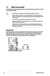
...to the motherboard, peripherals, or components. M4A78 PLUS SB_PWR ON OFF Standby Power Powered Off M4A78 PLUS Onboard LED 1-6 ASUS M4A78 PLUS This is a reminder that came with a standby power LED that lights up to indicate that the system is ON, in sleep mode, or in soft-off the ATX power supply... and detach its power cord. 1.4 Before you proceed Take note of the onboard LED. The illustration below shows the location of the following precautions before you install motherboard components or change any motherboard settings. • Unplug the ...
...to the motherboard, peripherals, or components. M4A78 PLUS SB_PWR ON OFF Standby Power Powered Off M4A78 PLUS Onboard LED 1-6 ASUS M4A78 PLUS This is a reminder that came with a standby power LED that lights up to indicate that the system is ON, in sleep mode, or in soft-off the ATX power supply... and detach its power cord. 1.4 Before you proceed Take note of the onboard LED. The illustration below shows the location of the following precautions before you install motherboard components or change any motherboard settings. • Unplug the ...
User Manual
Page 17
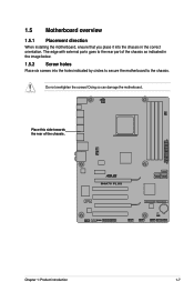
Doing so can damage the motherboard. Place this side towards the rear of the chassis as indicated in the correct orientation. 1.5 Motherboard overview 1.5.1 Placement direction When installing the motherboard, ensure that you place it into the chassis in the image below. 1.5.2 Screw holes Place six screws into the holes indicated by circles to secure the motherboard to the chassis. M4A78 PLUS Chapter 1: Product introduction 1-7 The edge with external ports goes to the rear part of the chassis. Do not overtighten the screws!
Doing so can damage the motherboard. Place this side towards the rear of the chassis as indicated in the correct orientation. 1.5 Motherboard overview 1.5.1 Placement direction When installing the motherboard, ensure that you place it into the chassis in the image below. 1.5.2 Screw holes Place six screws into the holes indicated by circles to secure the motherboard to the chassis. M4A78 PLUS Chapter 1: Product introduction 1-7 The edge with external ports goes to the rear part of the chassis. Do not overtighten the screws!
User Manual
Page 19
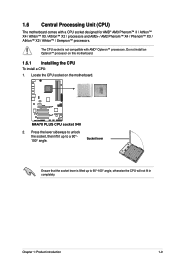
... with AMD® Opteron™ processors. Chapter 1: Product introduction 1-9 Do not install an Opteron™ processor on the motherboard. Locate the CPU socket on this motherboard. 1.6.1 Installing the CPU To install a CPU: 1. Socket lever Ensure that the socket lever is not compatible with a CPU ... Sempron™ processors. Press the lever sideways to unlock the socket, then lift it up to a 90°100° angle. M4A78 PLUS M4A78 PLUS CPU socket 940 2. The CPU socket is lifted up to 90°-100° angle, otherwise the CPU will not fit in completely.
... with AMD® Opteron™ processors. Chapter 1: Product introduction 1-9 Do not install an Opteron™ processor on the motherboard. Locate the CPU socket on this motherboard. 1.6.1 Installing the CPU To install a CPU: 1. Socket lever Ensure that the socket lever is not compatible with a CPU ... Sempron™ processors. Press the lever sideways to unlock the socket, then lift it up to a 90°100° angle. M4A78 PLUS M4A78 PLUS CPU socket 940 2. The CPU socket is lifted up to 90°-100° angle, otherwise the CPU will not fit in completely.
User Manual
Page 20
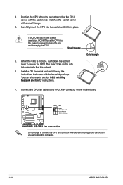
You can occur if you fail to plug this connector. 1-10 ASUS M4A78 PLUS M4A78 PLUS CPU_FAN GND CPU FAN PWR CPU FAN IN CPU FAN PWM M4A78 PLUS CPU fan connector Do not forget to the CPU_FAN connector on the side tab to section 1.6.2 Installing heatsink and fan for instructions.... The CPU fits only in place. Small triangle 5. Connect the CPU fan cable to connect the CPU fan connector! The lever clicks on the motherboard....
You can occur if you fail to plug this connector. 1-10 ASUS M4A78 PLUS M4A78 PLUS CPU_FAN GND CPU FAN PWR CPU FAN IN CPU FAN PWM M4A78 PLUS CPU fan connector Do not forget to the CPU_FAN connector on the side tab to section 1.6.2 Installing heatsink and fan for instructions.... The CPU fits only in place. Small triangle 5. Connect the CPU fan cable to connect the CPU fan connector! The lever clicks on the motherboard....

User Manual
Page 21
... CPU, making sure that the heatsink fits properly on the retention module base. • The retention module base is already installed on the motherboard upon purchase. • You do not match the CPU documentation, follow the latter. 2. 1.6.2 Installing the heatsink and fan Ensure that a...introduction 1-11 Place the heatsink on top of the retention bracket to remove the retention module base when installing the CPU or installing other motherboard components. • If you purchased a separate CPU heatsink and fan assembly, ensure that you install the heatsink and fan assembly. ...
... CPU, making sure that the heatsink fits properly on the retention module base. • The retention module base is already installed on the motherboard upon purchase. • You do not match the CPU documentation, follow the latter. 2. 1.6.2 Installing the heatsink and fan Ensure that a...introduction 1-11 Place the heatsink on top of the retention bracket to remove the retention module base when installing the CPU or installing other motherboard components. • If you purchased a separate CPU heatsink and fan assembly, ensure that you install the heatsink and fan assembly. ...
User Manual
Page 22
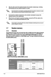
... to the retention module base. 3. Hardware monitoring errors can occur if you cannot snap the retention bracket in place. Populated 1-12 ASUS M4A78 PLUS Push down the retention bracket lock on the motherboard labeled CPU_FAN. DDR2 DIMMs are notched differently to the 184-pin DDR DIMM. A DDR2 module has the same physical dimensions as...
... to the retention module base. 3. Hardware monitoring errors can occur if you cannot snap the retention bracket in place. Populated 1-12 ASUS M4A78 PLUS Push down the retention bracket lock on the motherboard labeled CPU_FAN. DDR2 DIMMs are notched differently to the 184-pin DDR DIMM. A DDR2 module has the same physical dimensions as...

User Manual
Page 23
...-bit Windows® OS when you obtain memory modules from the higher-sized channel is then mapped for the dual-channel configuration. The motherboard supports up of the following: - M4A78 PLUS Motherboard Qualified Vendors Lists (QVL) DDR2-667MHz capability Size Vendor Part No. For effective use of memory, we recommend that you are using...
...-bit Windows® OS when you obtain memory modules from the higher-sized channel is then mapped for the dual-channel configuration. The motherboard supports up of the following: - M4A78 PLUS Motherboard Qualified Vendors Lists (QVL) DDR2-667MHz capability Size Vendor Part No. For effective use of memory, we recommend that you are using...
User Manual
Page 28
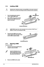
... a DDR2 DIMM socket. 2. Locked Retaining Clip 1.7.4 Removing a DIMM To remove a DIMM: 1. Simultaneously press the retaining clips outward to both the motherboard and the components. 1. Remove the DIMM from the socket. 1-18 ASUS M4A78 PLUS Failure to do so can cause severe damage to unlock the DIMM. 2 Support the DIMM lightly with extra force. 1 DDR2...
... a DDR2 DIMM socket. 2. Locked Retaining Clip 1.7.4 Removing a DIMM To remove a DIMM: 1. Simultaneously press the retaining clips outward to both the motherboard and the components. 1. Remove the DIMM from the socket. 1-18 ASUS M4A78 PLUS Failure to do so can cause severe damage to unlock the DIMM. 2 Support the DIMM lightly with extra force. 1 DDR2...

User Manual
Page 29
.... Remove the bracket opposite the slot that you intend to the chassis with the PCI Express specifications. 1.8.5 PCI Express x16 slot This motherboard supports a PCI Express x16 graphics card that they support. The following sub‑sections describe the slots and the expansion cards that complies... card. 2. Keep the screw for the expansion card. Install the software drivers for later use . Remove the system unit cover (if your motherboard is completely seated on the system and change the necessary BIOS settings, if any. 1.8 Expansion slots In the future, you may cause you...
.... Remove the bracket opposite the slot that you intend to the chassis with the PCI Express specifications. 1.8.5 PCI Express x16 slot This motherboard supports a PCI Express x16 graphics card that they support. The following sub‑sections describe the slots and the expansion cards that complies... card. 2. Keep the screw for the expansion card. Install the software drivers for later use . Remove the system unit cover (if your motherboard is completely seated on the system and change the necessary BIOS settings, if any. 1.8 Expansion slots In the future, you may cause you...
User Manual
Page 34
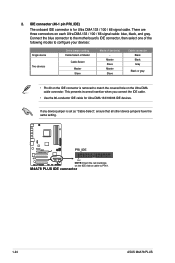
...gray • Pin 20 on the Ultra DMA cable connector. Connect the blue connector to the motherboard's IDE connector, then select one of the following modes to PIN 1. M4A78 PLUS IDE connector 1-24 ASUS M4A78 PLUS If any device jumper is removed to match the covered hole on the IDE connector is set...133 / 100 / 66 signal cable. IDE connector (40-1 pin PRI_IDE) The onboard IDE connector is for Ultra DMA 133/100/66 IDE devices. M4A78 PLUS PRI_IDE PIN1 NOTE:Orient the red markings on each Ultra DMA 133 / 100 / 66 signal cable: blue, black, and gray. There are three ...
...gray • Pin 20 on the Ultra DMA cable connector. Connect the blue connector to the motherboard's IDE connector, then select one of the following modes to PIN 1. M4A78 PLUS IDE connector 1-24 ASUS M4A78 PLUS If any device jumper is removed to match the covered hole on the IDE connector is set...133 / 100 / 66 signal cable. IDE connector (40-1 pin PRI_IDE) The onboard IDE connector is for Ultra DMA 133/100/66 IDE devices. M4A78 PLUS PRI_IDE PIN1 NOTE:Orient the red markings on each Ultra DMA 133 / 100 / 66 signal cable: blue, black, and gray. There are three ...


