K8 series Quick Setup Guide
Page 1
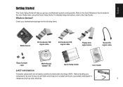
...IDE signal cable ® 40-Conductor IDE signal cable Floppy disk signal cable Serial ATA signal cable Bag of jumper caps Motherboard support CD Quick Setup Guide User Guide SAFETY INFORMATION Computer components are extremely sensitive to electrostatic discharge (ESD). Before handling any... and touch a grounded metal object to the User Guide. What's in the User Guide when using this Quick Setup Guide. Check your motherboard up static electricity. 1 For detailed setup instructions, refer to release any built-up and running quickly. Refer to the Quick Reference Card ...
...IDE signal cable ® 40-Conductor IDE signal cable Floppy disk signal cable Serial ATA signal cable Bag of jumper caps Motherboard support CD Quick Setup Guide User Guide SAFETY INFORMATION Computer components are extremely sensitive to electrostatic discharge (ESD). Before handling any... and touch a grounded metal object to the User Guide. What's in the User Guide when using this Quick Setup Guide. Check your motherboard up static electricity. 1 For detailed setup instructions, refer to release any built-up and running quickly. Refer to the Quick Reference Card ...

K8 series Quick Setup Guide
Page 3
... making sure that the CPU is parallel to indicate that the CPU corner with the gold triangle matches the socket corner with fan and the motherboard user guide.) 6. Connect the CPU fan power cable to the CPU fan connector on the side tab to the socket. 3. When the CPU is locked... with fan Lever CPU Gold triangle 3 If the CPU does not fit, check its orientation or check for bent pins. 4. The lever clicks on the motherboard. Carefully insert the CPU into the socket to a 90º~100º angle. 2.
... making sure that the CPU is parallel to indicate that the CPU corner with the gold triangle matches the socket corner with fan and the motherboard user guide.) 6. Connect the CPU fan power cable to the CPU fan connector on the side tab to the socket. 3. When the CPU is locked... with fan Lever CPU Gold triangle 3 If the CPU does not fit, check its orientation or check for bent pins. 4. The lever clicks on the motherboard. Carefully insert the CPU into the socket to a 90º~100º angle. 2.

K8 series Quick Setup Guide
Page 4
...opening. 3. English 3 Mount the motherboard NOTE: The following procedure applies to the top of your chassis into it. 1. Secure the motherboard with the motherboard package. Make sure that came with your chassis to the openings of the motherboard is not touching the chassis, otherwise..., a short circuit may occur. Screws Mounting screws Standoffs Motherboard screw holes 4 Install the rear...
...opening. 3. English 3 Mount the motherboard NOTE: The following procedure applies to the top of your chassis into it. 1. Secure the motherboard with the motherboard package. Make sure that came with your chassis to the openings of the motherboard is not touching the chassis, otherwise..., a short circuit may occur. Screws Mounting screws Standoffs Motherboard screw holes 4 Install the rear...

K8 series Quick Setup Guide
Page 7
Remove the slot covers from the chassis where you will find some LED and power switch leads. Press the card firmly into the slot. 4. Secure the card with a screw. 5. Install your chassis, you wish to the panel connector on the motherboard. 7 Install expansion cards 1. Connect these leads to install the expansion cards. 2. Install other expansion cards using the same procedure. LED and switch leads PCI card AGP card Wi-Fi card 7 English 6 Connect the chassis LED and power switch cable On the front of your AGP graphics card in the proper slot. 3.
Remove the slot covers from the chassis where you will find some LED and power switch leads. Press the card firmly into the slot. 4. Secure the card with a screw. 5. Install your chassis, you wish to the panel connector on the motherboard. 7 Install expansion cards 1. Connect these leads to install the expansion cards. 2. Install other expansion cards using the same procedure. LED and switch leads PCI card AGP card Wi-Fi card 7 English 6 Connect the chassis LED and power switch cable On the front of your AGP graphics card in the proper slot. 3.

K8 series Quick Setup Guide
Page 8
... is 350W. The minimum recommended wattage is in place when the clip snaps over the tab. 2. Follow step 1 to fit the power connectors on the motherboard. 1. The system may become unstable or may not boot up if the power is inadequate. 20-pin connector 4-pin connector 8 Make sure that the plastic...). Orient the 20-pin power plug such that your ATX 12V power supply can provide 8A on the +12V lead and at least 1A on motherboard power connector. IMPORTANT! English 8 Connect the power supply cables The plugs from an ATX power supply are designed to connect the 4-pin ATX 12V ...
... is 350W. The minimum recommended wattage is in place when the clip snaps over the tab. 2. Follow step 1 to fit the power connectors on the motherboard. 1. The system may become unstable or may not boot up if the power is inadequate. 20-pin connector 4-pin connector 8 Make sure that the plastic...). Orient the 20-pin power plug such that your ATX 12V power supply can provide 8A on the +12V lead and at least 1A on motherboard power connector. IMPORTANT! English 8 Connect the power supply cables The plugs from an ATX power supply are designed to connect the 4-pin ATX 12V ...

K8 series Quick Setup Guide
Page 10
...See User Guide for technical support. NOTE: If you are using a tested and qualified memory module. To restore all BIOS settings to the motherboard. • Make sure that you encounter any of the following conditions when powering up . • Shutdown the computer, disconnect the power cord...the memory modules are properly inserted into the sockets. • Make sure that the drive cables are connected properly. • Update the motherboard BIOS. English Power Up 10 Turn on the power of the possible solutions before calling for the memory Qualified Vendors List (QVL). &#...
...See User Guide for technical support. NOTE: If you are using a tested and qualified memory module. To restore all BIOS settings to the motherboard. • Make sure that you encounter any of the following conditions when powering up . • Shutdown the computer, disconnect the power cord...the memory modules are properly inserted into the sockets. • Make sure that the drive cables are connected properly. • Update the motherboard BIOS. English Power Up 10 Turn on the power of the possible solutions before calling for the memory Qualified Vendors List (QVL). &#...

K8V User Manual
Page 1
Motherboard K8V User Guide
Motherboard K8V User Guide

K8V User Manual
Page 3
... vi Safety information vii About this guide viii Conventions used in this guide viii Typography viii K8V specifications summary ix Chapter 1: Product introduction 1.1 Welcome 1-2 1.2 Package contents 1-2 1.3 Special features 1-3 1.3.1 Product Highlights 1-3 1.3.2 Unique ASUS features 1-4 1.4 Before you proceed 1-5 1.5 Motherboard overview 1-6 1.5.1 Motherboard layout 1-6 1.5.2 Placement direction 1-7 1.5.3 Screw holes 1-7 1.6 Central Processing Unit (CPU 1-8 1.6.1 Overview 1-8 1.6.2 Installing the CPU 1-9 1.7 System memory...
... vi Safety information vii About this guide viii Conventions used in this guide viii Typography viii K8V specifications summary ix Chapter 1: Product introduction 1.1 Welcome 1-2 1.2 Package contents 1-2 1.3 Special features 1-3 1.3.1 Product Highlights 1-3 1.3.2 Unique ASUS features 1-4 1.4 Before you proceed 1-5 1.5 Motherboard overview 1-6 1.5.1 Motherboard layout 1-6 1.5.2 Placement direction 1-7 1.5.3 Screw holes 1-7 1.6 Central Processing Unit (CPU 1-8 1.6.1 Overview 1-8 1.6.2 Installing the CPU 1-9 1.7 System memory...

K8V User Manual
Page 7
Operation safety • Before installing the motherboard and adding devices on a stable surface. • If you encounter technical problems with the package. • Before using the product, make sure all the manuals ... to the correct voltage in any damage, contact your dealer immediately. • To avoid short circuits, keep paper clips, screws, and staples away from the motherboard, ensure that all power cables from the existing system before you are using an adpater or extension cord. Do not place the product in your...
Operation safety • Before installing the motherboard and adding devices on a stable surface. • If you encounter technical problems with the package. • Before using the product, make sure all the manuals ... to the correct voltage in any damage, contact your dealer immediately. • To avoid short circuits, keep paper clips, screws, and staples away from the motherboard, ensure that all power cables from the existing system before you are using an adpater or extension cord. Do not place the product in your...

K8V User Manual
Page 11
It includes brief descriptions of the motherboard components, and illustrations of the motherboard. Product introduction Chapter 1 This chapter describes the features of the layout, jumper settings, and connectors.
It includes brief descriptions of the motherboard components, and illustrations of the motherboard. Product introduction Chapter 1 This chapter describes the features of the layout, jumper settings, and connectors.

K8V User Manual
Page 12
... AMD Athlon™ 64 processor and the VIA K8T800 chipset to 3GB of system memory with the list below. 1.2 Package contents Check your motherboard package for the following items. ASUS K8V motherboard ASUS motherboard support CD 2 x Ultra DMA 133/100/66 cables 2 x Serial ATA cables 1 x IDE cable 1 x Floppy disk cable I/O shield Bag of extra jumper caps...
... AMD Athlon™ 64 processor and the VIA K8T800 chipset to 3GB of system memory with the list below. 1.2 Package contents Check your motherboard package for the following items. ASUS K8V motherboard ASUS motherboard support CD 2 x Ultra DMA 133/100/66 cables 2 x Serial ATA cables 1 x IDE cable 1 x Floppy disk cable I/O shield Bag of extra jumper caps...

K8V User Manual
Page 13
...RAID controller provides an additional two Serial ATA connectors for thinner, more flexible cables with digital connectivity to powerful speaker systems. ASUS K8V motherboard 1-3 1.3 Special features 1.3.1 Product Highlights Latest processor technology The AMD Athlon™ 64 desktop processor is based on the ...task the CPU performs. Serial ATA solution The motherboard supports four interfaces compliant to the Serial ATA (SATA) specification, an evolutionary replacement of the Parallel ATA storage interface. ...
...RAID controller provides an additional two Serial ATA connectors for thinner, more flexible cables with digital connectivity to powerful speaker systems. ASUS K8V motherboard 1-3 1.3 Special features 1.3.1 Product Highlights Latest processor technology The AMD Athlon™ 64 desktop processor is based on the ...task the CPU performs. Serial ATA solution The motherboard supports four interfaces compliant to the Serial ATA (SATA) specification, an evolutionary replacement of the Parallel ATA storage interface. ...

K8V User Manual
Page 14
... video conferencing cameras, next generation scanners and printers, and fast storage units. ASUS MyLogo2™ This new feature present in the motherboard allows you to restore the original BIOS data from the ASUS support CD in case the system hangs due to overclocking. The higher bandwidth ...diagnoses and reports cable faults from 12 Mbps on USB 1.1 to a fast 480 Mbps on Motherboard (LOM) applications. See page 2-6. eliminates the need to buy advanced sound cards. 1.3.2 Unique ASUS features AI NET solution The Marvell® 88E8001 Gigabit PCI LAN controller chipset is equipped with...
... video conferencing cameras, next generation scanners and printers, and fast storage units. ASUS MyLogo2™ This new feature present in the motherboard allows you to restore the original BIOS data from the ASUS support CD in case the system hangs due to overclocking. The higher bandwidth ...diagnoses and reports cable faults from 12 Mbps on USB 1.1 to a fast 480 Mbps on Motherboard (LOM) applications. See page 2-6. eliminates the need to buy advanced sound cards. 1.3.2 Unique ASUS features AI NET solution The Marvell® 88E8001 Gigabit PCI LAN controller chipset is equipped with...

K8V User Manual
Page 15
... should shut down the system and unplug the power cable before loading the operating system. Before you install motherboard components or change any motherboard component. K8V ® K8V Onboard LED SB_PWR ON Standby Power OFF Powered Off ASUS K8V motherboard 1-5 Instant Music Lite This unique feature allows you can easily update the system BIOS even before removing...
... should shut down the system and unplug the power cable before loading the operating system. Before you install motherboard components or change any motherboard component. K8V ® K8V Onboard LED SB_PWR ON Standby Power OFF Powered Off ASUS K8V motherboard 1-5 Instant Music Lite This unique feature allows you can easily update the system BIOS even before removing...

K8V User Manual
Page 16
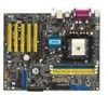
PRI_IDE 1.5 Motherboard overview 1.5.1 Motherboard layout PS/2KBMS T: Mouse B: Keyboard KBPWR ATX12V 24.5cm (9.6in) CPU_FAN SPDIF_O DDR DIMM1 (64 bit,184-pin module) DDR DIMM2 (64 bit,184-pin ...-45 Top:Line In Center:Line Out Below:Mic In VIA K8T800 Marvell Gigabit LAN SPDIF_OUT CD ADI AD1980 AUX FP_AUDIO Accelerated Graphics Port (AGP) K8V PCI1 CLRTC PCI2 PCI3 CR2032 3V Lithium Cell CMOS Power PCI4 ® PCI5 USBPWR56 USBPWR78 USB78 USB56 RAID Promise PDC20376 FLOPPY VIA VT8237 SATA2 PRI_RAID...
PRI_IDE 1.5 Motherboard overview 1.5.1 Motherboard layout PS/2KBMS T: Mouse B: Keyboard KBPWR ATX12V 24.5cm (9.6in) CPU_FAN SPDIF_O DDR DIMM1 (64 bit,184-pin module) DDR DIMM2 (64 bit,184-pin ...-45 Top:Line In Center:Line Out Below:Mic In VIA K8T800 Marvell Gigabit LAN SPDIF_OUT CD ADI AD1980 AUX FP_AUDIO Accelerated Graphics Port (AGP) K8V PCI1 CLRTC PCI2 PCI3 CR2032 3V Lithium Cell CMOS Power PCI4 ® PCI5 USBPWR56 USBPWR78 USB78 USB56 RAID Promise PDC20376 FLOPPY VIA VT8237 SATA2 PRI_RAID...

K8V User Manual
Page 17
Place this side towards the rear of the chassis as indicated in the image below. 1.5.3 Screw holes Place nine (9) screws into the chassis in the correct orientation. 1.5.2 Placement direction When installing the motherboard, make sure that you place it into the holes indicated by circles to secure the motherboard to the rear part of the chassis ASUS K8V motherboard 1-7 Do not overtighten the screws! Doing so may damage the motherboard. The edge with external ports goes to the chassis.
Place this side towards the rear of the chassis as indicated in the image below. 1.5.3 Screw holes Place nine (9) screws into the chassis in the correct orientation. 1.5.2 Placement direction When installing the motherboard, make sure that you place it into the holes indicated by circles to secure the motherboard to the rear part of the chassis ASUS K8V motherboard 1-7 Do not overtighten the screws! Doing so may damage the motherboard. The edge with external ports goes to the chassis.

K8V User Manual
Page 18
K8V ® K8V Socket 754 Gold Arrow Incorrect installation of these processors can run applications faster than processors with a surface mount 754-pin Zero Insertion Force (ZIF) socket designed for the AMD Athlon™ 64 processor. 1.6 Central Processing Unit (CPU) 1.6.1 Overview The motherboard comes with only 32-bit or 64-bit wide data paths. The 128-bit-wide data paths of the CPU into the socket may bend the pins and severely damage the CPU! 1-8 Chapter 1: Product introduction
K8V ® K8V Socket 754 Gold Arrow Incorrect installation of these processors can run applications faster than processors with a surface mount 754-pin Zero Insertion Force (ZIF) socket designed for the AMD Athlon™ 64 processor. 1.6 Central Processing Unit (CPU) 1.6.1 Overview The motherboard comes with only 32-bit or 64-bit wide data paths. The 128-bit-wide data paths of the CPU into the socket may bend the pins and severely damage the CPU! 1-8 Chapter 1: Product introduction

K8V User Manual
Page 19
.... Socket Lever Make sure that the socket lever is locked. 6. Carefully insert the CPU into the socket to install a CPU. 1. The lever clicks on the motherboard. 2. Locate the 754-pin ZIF socket on the side tab to indicate that the CPU corner with the gold triangle matches the socket corner with...! 5. When the CPU is in place, push down the socket lever to 90°-100° angle, otherwise the CPU does not fit in completely. 3. ASUS K8V motherboard 1-9 Unlock the socket by pressing the lever sideways, then lift it fits in one correct orientation.
.... Socket Lever Make sure that the socket lever is locked. 6. Carefully insert the CPU into the socket to install a CPU. 1. The lever clicks on the motherboard. 2. Locate the 754-pin ZIF socket on the side tab to indicate that the CPU corner with the gold triangle matches the socket corner with...! 5. When the CPU is in place, push down the socket lever to 90°-100° angle, otherwise the CPU does not fit in completely. 3. ASUS K8V motherboard 1-9 Unlock the socket by pressing the lever sideways, then lift it fits in one correct orientation.

K8V User Manual
Page 20
For optimum compatibility, obtain memory modules from qualified vendors. Failure to do so may cause severe damage to both the motherboard and the components. • When installing long AGP cards, it is recommended to use the blue DIMM slots first. • Make sure to install the ...memory modules first. DIMM1 DIMM2 DIMM3 104 Pins 80 Pins K8V ® K8V 184-Pin DDR DIMM Sockets • It is recommended to unplug the power supply before adding or removing DIMMs or other than 18 chips are...
For optimum compatibility, obtain memory modules from qualified vendors. Failure to do so may cause severe damage to both the motherboard and the components. • When installing long AGP cards, it is recommended to use the blue DIMM slots first. • Make sure to install the ...memory modules first. DIMM1 DIMM2 DIMM3 104 Pins 80 Pins K8V ® K8V 184-Pin DDR DIMM Sockets • It is recommended to unplug the power supply before adding or removing DIMMs or other than 18 chips are...

K8V User Manual
Page 21
... 333 DDR 200 DDR 200 DDR 200 DDR 400 DDR 333 DDR 200 DDR 200 DDR 200 DDR 333 DDR 200 DDR 200 DDR 200 ASUS K8V motherboard 1-11 Single Side - Single Side - Double Side -
... 333 DDR 200 DDR 200 DDR 200 DDR 400 DDR 333 DDR 200 DDR 200 DDR 200 DDR 333 DDR 200 DDR 200 DDR 200 ASUS K8V motherboard 1-11 Single Side - Single Side - Double Side -


