
Motherboard DIY Troubleshooting Guide
Page 1
K8N-VM Motherboard
K8N-VM Motherboard

Motherboard DIY Troubleshooting Guide
Page 3
Contents Notices vi Safety information vii k8N-VM specifications summary viii Chapter 1: Product introduction 1.1 Welcome 1-2 1.2 Package contents 1-2 1.3 Special features 1-2 1.3.1 Product highlights 1-2 1.3.2 Innovative ASUS features 1-4 1.4 Before you proceed 1-5 1.5 Motherboard overview 1-6 1.5.1 Motherboard layout 1-6 1.5.2 Placement direction 1-7 1.5.3 Screw holes 1-7 1.5.4 Layout contents 1-8 1.6 Central Processing Unit (CPU 1-9 1.7 System memory 1-11 1.7.1 Overview 1-11 1.7.2 Memory configurations 1-11 1.7.3 Installing a DIMM 1-14...
Contents Notices vi Safety information vii k8N-VM specifications summary viii Chapter 1: Product introduction 1.1 Welcome 1-2 1.2 Package contents 1-2 1.3 Special features 1-2 1.3.1 Product highlights 1-2 1.3.2 Innovative ASUS features 1-4 1.4 Before you proceed 1-5 1.5 Motherboard overview 1-6 1.5.1 Motherboard layout 1-6 1.5.2 Placement direction 1-7 1.5.3 Screw holes 1-7 1.5.4 Layout contents 1-8 1.6 Central Processing Unit (CPU 1-9 1.7 System memory 1-11 1.7.1 Overview 1-11 1.7.2 Memory configurations 1-11 1.7.3 Installing a DIMM 1-14...
Motherboard DIY Troubleshooting Guide
Page 12
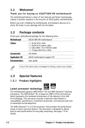
... hardware devices on AMDʼs 64-bit architecture, which represents the landmark introduction of ASUS quality motherboards! This processor is based on it another standout in -class performance for buying an ASUS® K8N-VM motherboard! See page 1-9 for the following items. Motherboard ASUS K8N-VM motherboard Cables 1 x Serial ATA cable 1 x Serial ATA power cable 1 x Ultra DMA 133/100/66 cable...
... hardware devices on AMDʼs 64-bit architecture, which represents the landmark introduction of ASUS quality motherboards! This processor is based on it another standout in -class performance for buying an ASUS® K8N-VM motherboard! See page 1-9 for the following items. Motherboard ASUS K8N-VM motherboard Cables 1 x Serial ATA cable 1 x Serial ATA power cable 1 x Ultra DMA 133/100/66 cable...
Motherboard DIY Troubleshooting Guide
Page 13
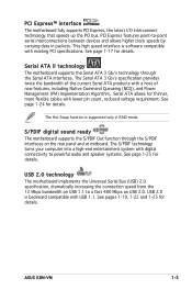
...cables with digital connectivity to -point serial interconnections between devices and allows higher clock speeds by carrying data in RAID mode. ASUS K8N-VM 1-3 The Serial ATA 3 Gb/s specification provides twice the bandwidth of the current Serial ATA products with existing ... with a host of new features, including Native Command Queueing (NCQ), and Power Management (PM) Implementation Algorithm. USB 2.0 technology The motherboard implements the Universal Serial Bus (USB) 2.0 specification, dramatically increasing the connection speed from the 12 Mbps bandwidth on USB 1.1...
...cables with digital connectivity to -point serial interconnections between devices and allows higher clock speeds by carrying data in RAID mode. ASUS K8N-VM 1-3 The Serial ATA 3 Gb/s specification provides twice the bandwidth of the current Serial ATA products with existing ... with a host of new features, including Native Command Queueing (NCQ), and Power Management (PM) Implementation Algorithm. USB 2.0 technology The motherboard implements the Universal Serial Bus (USB) 2.0 specification, dramatically increasing the connection speed from the 12 Mbps bandwidth on USB 1.1...
Motherboard DIY Troubleshooting Guide
Page 15
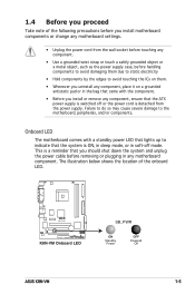
...the bag that you uninstall any component, place it on a grounded antistatic pad or in soft-off mode. R K8N-VM K8N-VM Onboard LED SB_PWR ON Standby Power OFF Powered Off ASUS K8N-VM 1-5 Failure to do so may cause severe damage to avoid touching the ICs on them. • Whenever you ...should shut down the system and unplug the power cable before handling components to avoid damaging them due to static electricity • Hold components by the edges to the motherboard...
...the bag that you uninstall any component, place it on a grounded antistatic pad or in soft-off mode. R K8N-VM K8N-VM Onboard LED SB_PWR ON Standby Power OFF Powered Off ASUS K8N-VM 1-5 Failure to do so may cause severe damage to avoid touching the ICs on them. • Whenever you ...should shut down the system and unplug the power cable before handling components to avoid damaging them due to static electricity • Hold components by the edges to the motherboard...

Motherboard DIY Troubleshooting Guide
Page 16
1.5 Motherboard overview 1.5.1 Motherboard layout 19.3cm (7.6in) PS/2 T: Mouse KBPWR B: Keyboard COM1 ATX12V CPU_FAN EATXPWR DDR DIMM1 (64 bit, 184-pin module) DDR DIMM2 (64 bit, 184-pin ... USBPW1234 Bottom: USB3 USB4 Top: RJ-45 Top:Line In Center:Line Out Below:Mic In Realtek 4Mb Flash ROM PCIEX1_1 Super I/O nVidia GeForce 6100 R K8N-VM PCIEX16 CD AAFP Audio SPDIF_OUT PCI1 SB_PWR PCI2 FLOPPY CR2032 3V Lithium Cell CMOS Powe nVidia nForce 410 SATA2 USBPW5678 USB56 USB78 SATA1 CLRTC PANEL...
1.5 Motherboard overview 1.5.1 Motherboard layout 19.3cm (7.6in) PS/2 T: Mouse KBPWR B: Keyboard COM1 ATX12V CPU_FAN EATXPWR DDR DIMM1 (64 bit, 184-pin module) DDR DIMM2 (64 bit, 184-pin ... USBPW1234 Bottom: USB3 USB4 Top: RJ-45 Top:Line In Center:Line Out Below:Mic In Realtek 4Mb Flash ROM PCIEX1_1 Super I/O nVidia GeForce 6100 R K8N-VM PCIEX16 CD AAFP Audio SPDIF_OUT PCI1 SB_PWR PCI2 FLOPPY CR2032 3V Lithium Cell CMOS Powe nVidia nForce 410 SATA2 USBPW5678 USB56 USB78 SATA1 CLRTC PANEL...

Motherboard DIY Troubleshooting Guide
Page 17
Doing so can damage the motherboard. Place this side towards the rear of the chassis as indicated in the image below. 1.5.3 Screw holes Place six (6) screws into the chassis in the correct orientation. The edge with external ports goes to the chassis. Do not overtighten the screws! 1.5.2 Placement direction When installing the motherboard, make sure that you place it into the holes indicated by circles to secure the motherboard to the rear part of the chassis R K8N-VM ASUS K8N-VM 1-7
Doing so can damage the motherboard. Place this side towards the rear of the chassis as indicated in the image below. 1.5.3 Screw holes Place six (6) screws into the chassis in the correct orientation. The edge with external ports goes to the chassis. Do not overtighten the screws! 1.5.2 Placement direction When installing the motherboard, make sure that you place it into the holes indicated by circles to secure the motherboard to the rear part of the chassis R K8N-VM ASUS K8N-VM 1-7
Motherboard DIY Troubleshooting Guide
Page 19
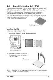
This mark should match a specific corner on the motherboard. ASUS K8N-VM 1-9 1.6 Central Processing Unit (CPU) The motherboard comes with only 32-bit or 64-bit wide data paths. The 128-bit-wide data paths of the marked corner (with gold triangle) on ... applications faster than processors with a surface mount 754-pin Zero Insertion Force (ZIF) socket designed for the AMD Athlon™ 64 and Sempron™ processor. R K8N-VM K8N-VM CPU Socket 754 2. Unlock the socket by pressing the lever sideways, then lift it up to install a CPU. 1.
This mark should match a specific corner on the motherboard. ASUS K8N-VM 1-9 1.6 Central Processing Unit (CPU) The motherboard comes with only 32-bit or 64-bit wide data paths. The 128-bit-wide data paths of the marked corner (with gold triangle) on ... applications faster than processors with a surface mount 754-pin Zero Insertion Force (ZIF) socket designed for the AMD Athlon™ 64 and Sempron™ processor. R K8N-VM K8N-VM CPU Socket 754 2. Unlock the socket by pressing the lever sideways, then lift it up to install a CPU. 1.

Motherboard DIY Troubleshooting Guide
Page 20
...small triangle. 4. Carefully insert the CPU into the socket to prevent bending the pins and damaging the CPU! 5. The lever clicks on the motherboard. Small triangle Gold triangle The CPU fits only in place. GND +12V Rotation 1-10 Chapter 1: Product introduction Hardware monitoring errors can... occur if you fail to connect the CPU fan connector! CPU_FAN R K8N-VM K8N-VM CPU Fan Connector Do not forget to plug this connector. DO NOT force the CPU into the socket until it is in place, ...
...small triangle. 4. Carefully insert the CPU into the socket to prevent bending the pins and damaging the CPU! 5. The lever clicks on the motherboard. Small triangle Gold triangle The CPU fits only in place. GND +12V Rotation 1-10 Chapter 1: Product introduction Hardware monitoring errors can... occur if you fail to connect the CPU fan connector! CPU_FAN R K8N-VM K8N-VM CPU Fan Connector Do not forget to plug this connector. DO NOT force the CPU into the socket until it is in place, ...
Motherboard DIY Troubleshooting Guide
Page 21
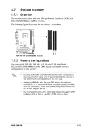
...to the DDR400 Qualified Vendors List on the next page. • Always install DIMMs with the same CAS latency. DIMM1 DIMM2 ASUS K8N-VM 1-11 For optimum compatibility, it is recommended that you obtain memory modules from the same vendor. The following figure illustrates the location ... to chipset limitation, this section. • Installing DDR DIMMs other than or equal to 128 Mb memory chips. 1.7 System memory 1.7.1 Overview The motherboard comes with less than the recommended configurations may install 128 MB, 256 MB, 512 MB, and 1 GB unbuffered ECC/non-ECC DDR ...
...to the DDR400 Qualified Vendors List on the next page. • Always install DIMMs with the same CAS latency. DIMM1 DIMM2 ASUS K8N-VM 1-11 For optimum compatibility, it is recommended that you obtain memory modules from the same vendor. The following figure illustrates the location ... to chipset limitation, this section. • Installing DDR DIMMs other than or equal to 128 Mb memory chips. 1.7 System memory 1.7.1 Overview The motherboard comes with less than the recommended configurations may install 128 MB, 256 MB, 512 MB, and 1 GB unbuffered ECC/non-ECC DDR ...

Motherboard DIY Troubleshooting Guide
Page 25
...The following sub-sections describe the slots and the expansion cards that you intend to use . 4. Remove the system unit cover (if your motherboard is completely seated on the next page. 3. Install the software drivers for later use . Replace the system cover. 1.8.2 Configuring an expansion... with the slot and press firmly until the card is already installed in a chassis). 3. See Chapter 2 for the card. 2. ASUS K8N-VM 1-15 Secure the card to unplug the power cord before adding or removing expansion cards. Assign an IRQ to install expansion cards. Before installing ...
...The following sub-sections describe the slots and the expansion cards that you intend to use . 4. Remove the system unit cover (if your motherboard is completely seated on the next page. 3. Install the software drivers for later use . Replace the system cover. 1.8.2 Configuring an expansion... with the slot and press firmly until the card is already installed in a chassis). 3. See Chapter 2 for the card. 2. ASUS K8N-VM 1-15 Secure the card to unplug the power cord before adding or removing expansion cards. Assign an IRQ to install expansion cards. Before installing ...
Motherboard DIY Troubleshooting Guide
Page 27
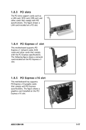
... with PCI Express specifications. The following figure shows a network card installed on a PCI slot. 1.8.4 PCI Express x1 slot This motherboard supports PCI Express x1 network cards, SCSI cards and other cards that comply with the PCI Express specifications. The figure shows a... graphics card installed on the PCI Express x16 slot. ASUS K8N-VM 1-17 1.8.3 PCI slots The PCI slots support cards such as a LAN card, SCSI card, USB card, and other cards that comply with ...
... with PCI Express specifications. The following figure shows a network card installed on a PCI slot. 1.8.4 PCI Express x1 slot This motherboard supports PCI Express x1 network cards, SCSI cards and other cards that comply with the PCI Express specifications. The figure shows a... graphics card installed on the PCI Express x16 slot. ASUS K8N-VM 1-17 1.8.3 PCI slots The PCI slots support cards such as a LAN card, SCSI card, USB card, and other cards that comply with ...
Motherboard DIY Troubleshooting Guide
Page 33
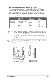
... • Use the 80-conductor IDE cable for Ultra DMA 133/100/66 signal cables. If any device jumper is removed to PIN 1. 2. ASUS K8N-VM 1-23 IDE connectors (40-1 pin PRI_IDE, SEC_IDE) The onboard IDE connectors are three connectors on the IDE ribbon cable to match the covered hole on...gure your devices. Single device Two devices Drive jumper setting Cable-Select or Master Cable-Select Master Slave Mode of the following modes to the motherboardʼs IDE connector, then select one of device(s) Master Slave Master Slave Cable connector Black Black Gray Black or gray • Pin ...
... • Use the 80-conductor IDE cable for Ultra DMA 133/100/66 signal cables. If any device jumper is removed to PIN 1. 2. ASUS K8N-VM 1-23 IDE connectors (40-1 pin PRI_IDE, SEC_IDE) The onboard IDE connectors are three connectors on the IDE ribbon cable to match the covered hole on...gure your devices. Single device Two devices Drive jumper setting Cable-Select or Master Cable-Select Master Slave Mode of the following modes to the motherboardʼs IDE connector, then select one of device(s) Master Slave Master Slave Cable connector Black Black Gray Black or gray • Pin ...
Motherboard DIY Troubleshooting Guide
Page 36
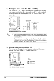
... definition Legacy AC'97-compliant pin definition AAFP AGND NC NC NC MIC2_L MIC2_R Line out_R NC Line out_L PORT1 L PORT1 R PORT2 R SENSE_SEND PORT2 L K8N-VM Analog Front Panel Connector • We recommend that you connect a high-definition front panel audio module to this connector to avail of the... is set to this connector, make sure that supports either High Definition Audio or AC `97 audio standard. Connect one end of the motherboard high-definition audio capability. • If you to receive stereo audio input from sound sources such as a CD-ROM, TV tuner, ...
... definition Legacy AC'97-compliant pin definition AAFP AGND NC NC NC MIC2_L MIC2_R Line out_R NC Line out_L PORT1 L PORT1 R PORT2 R SENSE_SEND PORT2 L K8N-VM Analog Front Panel Connector • We recommend that you connect a high-definition front panel audio module to this connector to avail of the... is set to this connector, make sure that supports either High Definition Audio or AC `97 audio standard. Connect one end of the motherboard high-definition audio capability. • If you to receive stereo audio input from sound sources such as a CD-ROM, TV tuner, ...

Motherboard DIY Troubleshooting Guide
Page 41
...64257;le to the floppy disk drive. Insert the floppy disk that you to update the BIOS without having to K8NVM.ROM. ASUS K8N-VM 2-3 Start erasing.......| Start programming...| Flashed successfully. Press + during the Power-On Self-Test (POST). When the correct BIOS file is ..., then restart the system. 3. A "K8NVM.ROM not found!" Copy the original or the latest motherboard BIOS file to the bootable floppy disk. 2.1.2 ASUS EZ Flash utility The ASUS EZ Flash feature allows you rename the BIOS file to go through the long process of booting...
...64257;le to the floppy disk drive. Insert the floppy disk that you to update the BIOS without having to K8NVM.ROM. ASUS K8N-VM 2-3 Start erasing.......| Start programming...| Flashed successfully. Press + during the Power-On Self-Test (POST). When the correct BIOS file is ..., then restart the system. 3. A "K8NVM.ROM not found!" Copy the original or the latest motherboard BIOS file to the bootable floppy disk. 2.1.2 ASUS EZ Flash utility The ASUS EZ Flash feature allows you rename the BIOS file to go through the long process of booting...

Motherboard DIY Troubleshooting Guide
Page 43
...of paper. All rights reserved. Write the BIOS filename on the bootable floppy disk. Reboot the system from the motherboard support CD to the bootable floppy disk you created earlier. 3. All rights reserved. done Writing flash .... 0x0008CC00 (9%)... Copyright (C) 2002 American Megatrends, Inc. Version 1.10 Copyright (C) 2002 American Megatrends, Inc. Visit the ASUS website (www.asus.com) and download the latest BIOS file for the motherboard. Reading file ..... A:\>afudos /iK8NVM.ROM 4. done Erasing flash .... The utility veri&#...
...of paper. All rights reserved. Write the BIOS filename on the bootable floppy disk. Reboot the system from the motherboard support CD to the bootable floppy disk you created earlier. 3. All rights reserved. done Writing flash .... 0x0008CC00 (9%)... Copyright (C) 2002 American Megatrends, Inc. Version 1.10 Copyright (C) 2002 American Megatrends, Inc. Visit the ASUS website (www.asus.com) and download the latest BIOS file for the motherboard. Reading file ..... A:\>afudos /iK8NVM.ROM 4. done Erasing flash .... The utility veri&#...

Motherboard DIY Troubleshooting Guide
Page 45
...BIOS! Bad BIOS checksum. Checking for CD-ROM... Visit the ASUS website (www.asus.com) to the optical drive. 3. When no floppy disk is found, the utility automatically checks the optical drive for this motherboard. Start flashing... Floppy not found ! Reading fi... the original or updated BIOS file. Restart the system after the utility completes the updating process. CD-ROM found ! ASUS K8N-VM 2-7 The utility displays the following message and automatically checks the floppy disk for floppy... Checking for the original or...
...BIOS! Bad BIOS checksum. Checking for CD-ROM... Visit the ASUS website (www.asus.com) to the optical drive. 3. When no floppy disk is found, the utility automatically checks the optical drive for this motherboard. Start flashing... Floppy not found ! Reading fi... the original or updated BIOS file. Restart the system after the utility completes the updating process. CD-ROM found ! ASUS K8N-VM 2-7 The utility displays the following message and automatically checks the floppy disk for floppy... Checking for the original or...

Motherboard DIY Troubleshooting Guide
Page 49
... purposes only, and may not exactly match what you can enable the security password feature or change the configuration of your BIOS." ASUS K8N-VM 2-11 The firmware hub on . Use the BIOS Setup program when you are not prompted to use as easy to run this ...the Setup program, you can change the power management settings. Select the Load Default Settings item under the Exit Menu. 2.2 BIOS setup program This motherboard supports a programmable firmware chip that the computer can recognize these changes and record them in the CMOS RAM or the firmware hub....
... purposes only, and may not exactly match what you can enable the security password feature or change the configuration of your BIOS." ASUS K8N-VM 2-11 The firmware hub on . Use the BIOS Setup program when you are not prompted to use as easy to run this ...the Setup program, you can change the power management settings. Select the Load Default Settings item under the Exit Menu. 2.2 BIOS setup program This motherboard supports a programmable firmware chip that the computer can recognize these changes and record them in the CMOS RAM or the firmware hub....

Motherboard DIY Troubleshooting Guide
Page 71
...] / [N/A] The onboard hardware monitor automatically detects and displays the CPU fan speed in rotations per minute (RPM). If the fan is not connected to the motherboard, the field shows N/A. ASUS K8N-VM 2-33 If the fan is not connected to the...
...] / [N/A] The onboard hardware monitor automatically detects and displays the CPU fan speed in rotations per minute (RPM). If the fan is not connected to the motherboard, the field shows N/A. ASUS K8N-VM 2-33 If the fan is not connected to the...

K8N-VM User's Manual for English Edition
Page 1
K8N-VM Motherboard
K8N-VM Motherboard


