
User Guide
Page 1
Motherboard J1800I-C/BR
Motherboard J1800I-C/BR
User Guide
Page 3
Contents Safety information...iv About this guide...iv Package contents...vi J1800I-C/BR specifications summary vi Chapter 1: Product introduction 1.1 Before you proceed 1-1 1.2 Motherboard overview 1-2 1.3 Central Processing Unit (CPU 1-4 1.4 System memory 1-4 1.5 Expansion slots 1-6 1.6 Jumpers...1-7 1.7 Connectors...1-9 1.8 Software support ... program 2-6 2.3 My Favorites 2-9 2.4 Main menu 2-10 2.5 Advanced menu 2-12 2.6 Monitor menu 2-19 2.7 Boot menu 2-22 2.8 Tools menu 2-27 2.9 Exit menu...2-28 Appendices Notices...A-1 ASUS contact information A-4 iii
Contents Safety information...iv About this guide...iv Package contents...vi J1800I-C/BR specifications summary vi Chapter 1: Product introduction 1.1 Before you proceed 1-1 1.2 Motherboard overview 1-2 1.3 Central Processing Unit (CPU 1-4 1.4 System memory 1-4 1.5 Expansion slots 1-6 1.6 Jumpers...1-7 1.7 Connectors...1-9 1.8 Software support ... program 2-6 2.3 My Favorites 2-9 2.4 Main menu 2-10 2.5 Advanced menu 2-12 2.6 Monitor menu 2-19 2.7 Boot menu 2-22 2.8 Tools menu 2-27 2.9 Exit menu...2-28 Appendices Notices...A-1 ASUS contact information A-4 iii
User Guide
Page 6
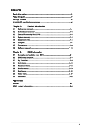
...) vi Supports Jack-Detection, and Front Panel Jack-Retasking • Use a chassis with HD audio module in the front panel to www.asus.com for the following items. Motherboard ASUS J1800I-C/BR motherboard Cables 2 x Serial ATA 3.0 Gb/s cables Accessories 1 x I/O Shields Application DVD Support DVD Documentation User Guide If any of the above items is...
...) vi Supports Jack-Detection, and Front Panel Jack-Retasking • Use a chassis with HD audio module in the front panel to www.asus.com for the following items. Motherboard ASUS J1800I-C/BR motherboard Cables 2 x Serial ATA 3.0 Gb/s cables Accessories 1 x I/O Shields Application DVD Support DVD Documentation User Guide If any of the above items is...

User Guide
Page 7
...BIOS, PnP, DMI2.0, WfM2.0,SM BIOS 2.7, ACPI 2.0a, Multi-language BIOS, ASUS EZ Flash 2, ASUS CrashFree BIOS 3, My Favorites, Quick Note, Last Modified log, F12 PrintScreen, F3 Shortcut functions and ASUS DRAM SPD (Serial Presence Detect) memory information Wfm 2.0, DMI 2.0, WOL by ...PME, PXE Drivers ASUS utilities EZ Update Anti-virus software (OEM version) Mini ITX Form Factor, 6.7" x 6.7" (17cm x 17cm) Specifications are subject to change without notice. vii ASUS MyLogo 2 - J1800I-C/BR specifications summary ASUS Unique Features Back Panel I/O Ports Internal I/O ...
...BIOS, PnP, DMI2.0, WfM2.0,SM BIOS 2.7, ACPI 2.0a, Multi-language BIOS, ASUS EZ Flash 2, ASUS CrashFree BIOS 3, My Favorites, Quick Note, Last Modified log, F12 PrintScreen, F3 Shortcut functions and ASUS DRAM SPD (Serial Presence Detect) memory information Wfm 2.0, DMI 2.0, WOL by ...PME, PXE Drivers ASUS utilities EZ Update Anti-virus software (OEM version) Mini ITX Form Factor, 6.7" x 6.7" (17cm x 17cm) Specifications are subject to change without notice. vii ASUS MyLogo 2 - J1800I-C/BR specifications summary ASUS Unique Features Back Panel I/O Ports Internal I/O ...

User Guide
Page 9
... you install or remove any component, ensure that the ATX power supply is switched off or the power cord is detached from the power supply. ASUS J1800I-C/BR 1-1
... you install or remove any component, ensure that the ATX power supply is switched off or the power cord is detached from the power supply. ASUS J1800I-C/BR 1-1

User Guide
Page 10
... fits into it into the holes indicated by circles to secure the motherboard to the chassis. Place this side towards the rear of the chassis J1800I-C/BR 1-2 Chapter 1: Product introduction Do not overtighten the screws! Ensure that you unplug the power cord before installing or removing the motherboard. Doing so can cause...
... fits into it into the holes indicated by circles to secure the motherboard to the chassis. Place this side towards the rear of the chassis J1800I-C/BR 1-2 Chapter 1: Product introduction Do not overtighten the screws! Ensure that you unplug the power cord before installing or removing the motherboard. Doing so can cause...

User Guide
Page 11
...pin TPM) 11. USB device wake-up (3-pin USBPWB) 5 7 Page 1-13 1-8 1-12 1-11 1-4 1-12 1-14 1-15 1-7 1-14 1-11 1-4 1-13 1-8 1-8 ASUS J1800I-C/BR 1-3 COM port connector (10-1 pin COM1) 5. USB device wake-up (3-pin USBPWF) 15. USB 2.0 connector (10-1 pin USB_23) 14. DDR3 SO-DIMM sockets 6. Front ...panel audio connector (10-1 pin AAFP) 12. VGA COM2 DDR3_DIMM_B1 (64bit, 204-pin module) SATA3G_1 SATA3G_2 J1800I-C/BR 17.0cm(6.7in) 1.2.3 Motherboard layout 12 3 45 6 17.0cm(6.7in) 15 14 13 6 12 KBMS_USB_E34 LAN_USB_E12 USB3_1 LPT COM1 KBPWR Super ...
...pin TPM) 11. USB device wake-up (3-pin USBPWB) 5 7 Page 1-13 1-8 1-12 1-11 1-4 1-12 1-14 1-15 1-7 1-14 1-11 1-4 1-13 1-8 1-8 ASUS J1800I-C/BR 1-3 COM port connector (10-1 pin COM1) 5. USB device wake-up (3-pin USBPWF) 15. USB 2.0 connector (10-1 pin USB_23) 14. DDR3 SO-DIMM sockets 6. Front ...panel audio connector (10-1 pin AAFP) 12. VGA COM2 DDR3_DIMM_B1 (64bit, 204-pin module) SATA3G_1 SATA3G_2 J1800I-C/BR 17.0cm(6.7in) 1.2.3 Motherboard layout 12 3 45 6 17.0cm(6.7in) 15 14 13 6 12 KBMS_USB_E34 LAN_USB_E12 USB3_1 LPT COM1 KBPWR Super ...
User Guide
Page 12
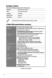
... model supports a maximum total memory of of memory. DDR3 1066Mhz memory modules are not supported. 1-4 Chapter 1: Product introduction APU J1800I-C/BR APU J1800I-C/BR 1.4 System memory 1.4.1 Overview This motherboard comes with an onboard Intel® Celeron™ Dual-core Processor J1800 and a specially ... same size and type of 8GB DDR3 1333 only. The figure illustrates the location of the DDR3 DIMM sockets: DIMM_A1 J1800I-C/BR DIMM_B1 J1800I-C/BR 204-pin DDR3 SO-DIMM sockets Channel Channel A Channel B Sockets DIMM_A1 DIMM_B1 • Using both memory channels is supported...
... model supports a maximum total memory of of memory. DDR3 1066Mhz memory modules are not supported. 1-4 Chapter 1: Product introduction APU J1800I-C/BR APU J1800I-C/BR 1.4 System memory 1.4.1 Overview This motherboard comes with an onboard Intel® Celeron™ Dual-core Processor J1800 and a specially ... same size and type of 8GB DDR3 1333 only. The figure illustrates the location of the DDR3 DIMM sockets: DIMM_A1 J1800I-C/BR DIMM_B1 J1800I-C/BR 204-pin DDR3 SO-DIMM sockets Channel Channel A Channel B Sockets DIMM_A1 DIMM_B1 • Using both memory channels is supported...

User Guide
Page 13
... TRANSCEND TS1GSK64W6H 8GB DS ADATA ADDS1600W4G11-B 4GB DS ADATA ADDS1600W8G11-B 8GB DS PQI MFCDR521UA0101 4GB DS PQI MFCDR621UA0103 8GB DS NANYA NT5CC512M8CN-DI - - PQI PQD312O8D12R - ASUS J1800I-C/BR 1-5 1.4.2 Memory configurations You may install 1GB, 2GB, 4GB and 8GB unbuffered non‑ECC DDR3 SO-DIMMs into both the slots. • Using both memory...
... TRANSCEND TS1GSK64W6H 8GB DS ADATA ADDS1600W4G11-B 4GB DS ADATA ADDS1600W8G11-B 8GB DS PQI MFCDR521UA0101 4GB DS PQI MFCDR621UA0103 8GB DS NANYA NT5CC512M8CN-DI - - PQI PQD312O8D12R - ASUS J1800I-C/BR 1-5 1.4.2 Memory configurations You may install 1GB, 2GB, 4GB and 8GB unbuffered non‑ECC DDR3 SO-DIMMs into both the slots. • Using both memory...
User Guide
Page 15
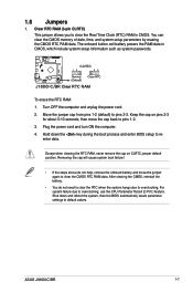
...; If the steps above do not need to clear the RTC when the system hangs due to overclocking, use the CPU Parameter Recall (C.P.R.) feature. ASUS J1800I-C/BR 1-7 Clear RTC RAM (3-pin CLRTC) This jumper allows you to clear the CMOS RTC RAM data. For system failure due to overclocking. 1.6 Jumpers... battery and move the cap back to default values. The onboard button cell battery powers the RAM data in CMOS. J1800I-C/BR CLRTC 12 23 Normal (Default) Clear RTC J1800I-C/BR Clear RTC RAM To erase the RTC RAM: 1. Move the jumper cap from pins 1-2 (default) to reenter data...
...; If the steps above do not need to clear the RTC when the system hangs due to overclocking, use the CPU Parameter Recall (C.P.R.) feature. ASUS J1800I-C/BR 1-7 Clear RTC RAM (3-pin CLRTC) This jumper allows you to clear the CMOS RTC RAM data. For system failure due to overclocking. 1.6 Jumpers... battery and move the cap back to default values. The onboard button cell battery powers the RAM data in CMOS. J1800I-C/BR CLRTC 12 23 Normal (Default) Clear RTC J1800I-C/BR Clear RTC RAM To erase the RTC RAM: 1. Move the jumper cap from pins 1-2 (default) to reenter data...

User Guide
Page 16
... up the computer from S3 and S4 sleep modes (no power to wake up feature. KBPWR 12 23 +5V (Default) +5VSB J1800I-C/BR J1800I-C/BR Keyboard power setting 3. USB device wake-up (3-pin USBPWF) Set this jumper to enable or disable the keyboard wake-up from S1 ...+5VSB to CPU, DRAM in slow refresh, power supply in the BIOS. J1800I-C/BR USBPWB 12 23 +5V +5VSB (Default) J1800I-C/BR USB device wake up 1-8 Chapter 1: Product introduction J1800I-C/BR USBPWF 12 23 +5V +5VSB (Default) J1800I-C/BR USB device wake up 4. When you can supply at least 1A on the...
... up the computer from S3 and S4 sleep modes (no power to wake up feature. KBPWR 12 23 +5V (Default) +5VSB J1800I-C/BR J1800I-C/BR Keyboard power setting 3. USB device wake-up (3-pin USBPWF) Set this jumper to enable or disable the keyboard wake-up from S1 ...+5VSB to CPU, DRAM in slow refresh, power supply in the BIOS. J1800I-C/BR USBPWB 12 23 +5V +5VSB (Default) J1800I-C/BR USB device wake up 1-8 Chapter 1: Product introduction J1800I-C/BR USBPWF 12 23 +5V +5VSB (Default) J1800I-C/BR USB device wake up 4. When you can supply at least 1A on the...
User Guide
Page 17
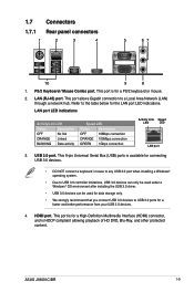
...) port. Refer to a Local Area Network (LAN) through a network hub. 1.7 Connectors 1.7.1 Rear panel connectors 1 2 3 4 5 67 10 9 8 1. This port is for the LAN port LED indications. ASUS J1800I-C/BR 1-9
...) port. Refer to a Local Area Network (LAN) through a network hub. 1.7 Connectors 1.7.1 Rear panel connectors 1 2 3 4 5 67 10 9 8 1. This port is for the LAN port LED indications. ASUS J1800I-C/BR 1-9
User Guide
Page 19
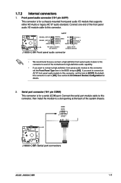
...'97 front panel audio module to this connector, set the Front Panel Type item in the BIOS setup to avail of the system chassis. AAFP J1800I-C/BR SENSE2_RETUR SENSE1_RETUR NC AGND PORT2 L NC SENSE_SEND PORT2 R NC PORT1 R NC PORT1 L AGND PIN 1 Line out_L NC Line out_R MICPWR MIC2... that supports either HD Audio or legacy AC`97 audio standard. COM1 PIN 1 RXD DTR DSR CTS DCD TXD GND RTS RI J1800I-C/BR J1800I-C/BR Serial port connectors ASUS J1800I-C/BR 1-11 Connect one end of the front panel audio I /O module that you want to connect a high-definition front panel audio ...
...'97 front panel audio module to this connector, set the Front Panel Type item in the BIOS setup to avail of the system chassis. AAFP J1800I-C/BR SENSE2_RETUR SENSE1_RETUR NC AGND PORT2 L NC SENSE_SEND PORT2 R NC PORT1 R NC PORT1 L AGND PIN 1 Line out_L NC Line out_R MICPWR MIC2... that supports either HD Audio or legacy AC`97 audio standard. COM1 PIN 1 RXD DTR DSR CTS DCD TXD GND RTS RI J1800I-C/BR J1800I-C/BR Serial port connectors ASUS J1800I-C/BR 1-11 Connect one end of the front panel audio I /O module that you want to connect a high-definition front panel audio ...

User Guide
Page 20
...GND GND +3 Volts +12 Volts +12 Volts +5V Standby Power OK GND +5 Volts GND +5 Volts GND +3 Volts +3 Volts PIN 1 J1800I-C/BR PIN 1 J1800I-C/BR ATX power connectors • For a fully configured system, we recommend that complies with more power-consuming devices. com/PowerSupplyCalculator/PSCalculator.aspx?SLanguage=en-...Recommended Power Supply Wattage Calculator at http://support.asus. LPT AFD ERR# INIT# SLIN# GND GND GND GND GND GND GND GND J1800I-C/BR PIN 1 STB# PD0 PD1 PD2 PD3 PD4 PD5 PD6 PD7 ACK# BUSY PE SLCT J1800I-C/BR Parallel port connector 1-12 Chapter 1: Product ...
...GND GND +3 Volts +12 Volts +12 Volts +5V Standby Power OK GND +5 Volts GND +5 Volts GND +3 Volts +3 Volts PIN 1 J1800I-C/BR PIN 1 J1800I-C/BR ATX power connectors • For a fully configured system, we recommend that complies with more power-consuming devices. com/PowerSupplyCalculator/PSCalculator.aspx?SLanguage=en-...Recommended Power Supply Wattage Calculator at http://support.asus. LPT AFD ERR# INIT# SLIN# GND GND GND GND GND GND GND GND J1800I-C/BR PIN 1 STB# PD0 PD1 PD2 PD3 PD4 PD5 PD6 PD7 ACK# BUSY PE SLCT J1800I-C/BR Parallel port connector 1-12 Chapter 1: Product ...

User Guide
Page 21
... USB 2.0 specification that the black wire of each cable matches the ground pin of the system chassis. ASUS J1800I-C/BR 1-13 J1800I-C/BR USB_23 PIN 1 +5V USB6USB6+ GND +5V USB5USB5+ GND (NC) J1800I-C/BR USB 2.0 connectors Never connect a 1394 cable to the fan connectors. USB 2.0 connector (10-1 pin ...USB_23) This connector is purchased separately. CHA_FAN CHA FAN PWM CHA FAN SENSE CHA FAN VCC GND CPU_FAN J1800I-C/BR Fan connectors Do not forget to connect the fan cables to the USB connector. CPU and chassis fan connectors (4-pin CPU_FAN, 4-...
... USB 2.0 specification that the black wire of each cable matches the ground pin of the system chassis. ASUS J1800I-C/BR 1-13 J1800I-C/BR USB_23 PIN 1 +5V USB6USB6+ GND +5V USB5USB5+ GND (NC) J1800I-C/BR USB 2.0 connectors Never connect a 1394 cable to the fan connectors. USB 2.0 connector (10-1 pin ...USB_23) This connector is purchased separately. CHA_FAN CHA FAN PWM CHA FAN SENSE CHA FAN VCC GND CPU_FAN J1800I-C/BR Fan connectors Do not forget to connect the fan cables to the USB connector. CPU and chassis fan connectors (4-pin CPU_FAN, 4-...

User Guide
Page 22
SATA3G_2 GND RSATA_TXP2 RSATA_TXN2 GND RSATA_RXN2 RSATA_RXP2 GND SATA3G_1 GND RSATA_TXP1 RSATA_TXN1 GND RSATA_RXN1 RSATA_RXP1 GND J1800I-C/BR SATA 3.0Gb/s connectors • You must install Windows® XP Service Pack 3 or later version before using Serial ATA hard disk drives. &#...Serial ATA 3.0 Gb/s hard disk drive or optical drive via Serial ATA 3.0 Gb/s signal cables. TPM PIN 1 J1800I-C/BR TPM connector S_PWRDWN GND +3VSB NC LAD0 +3V LAD3 PCIRST# FRAME PCICLK J1800I-C/BR NC CLK_RUN SERIRQ NC GND LAD1 LAD2 NC GND 1-14 Chapter 1: Product introduction TPM connector (20-1 pin TPM) ...
SATA3G_2 GND RSATA_TXP2 RSATA_TXN2 GND RSATA_RXN2 RSATA_RXP2 GND SATA3G_1 GND RSATA_TXP1 RSATA_TXN1 GND RSATA_RXN1 RSATA_RXP1 GND J1800I-C/BR SATA 3.0Gb/s connectors • You must install Windows® XP Service Pack 3 or later version before using Serial ATA hard disk drives. &#...Serial ATA 3.0 Gb/s hard disk drive or optical drive via Serial ATA 3.0 Gb/s signal cables. TPM PIN 1 J1800I-C/BR TPM connector S_PWRDWN GND +3VSB NC LAD0 +3V LAD3 PCIRST# FRAME PCICLK J1800I-C/BR NC CLK_RUN SERIRQ NC GND LAD1 LAD2 NC GND 1-14 Chapter 1: Product introduction TPM connector (20-1 pin TPM) ...

User Guide
Page 23
... +PWR LED PWR BTN PIN 1 +HDD_LED RESET J1800I-C/BR System panel connector • System power LED (2-pin PWRLED) This 2-pin connector is read from or written to this connector. The HD LED lights up ... data is for the HDD Activity LED. PWR_LED+ PWR_LEDPWR GND HDD_LED+ HDD_LED- System panel connector (10-1 pin F_PANEL) This connector supports several chassis-mounted functions. ASUS J1800I-C/BR 1-15
... +PWR LED PWR BTN PIN 1 +HDD_LED RESET J1800I-C/BR System panel connector • System power LED (2-pin PWRLED) This 2-pin connector is read from or written to this connector. The HD LED lights up ... data is for the HDD Activity LED. PWR_LED+ PWR_LEDPWR GND HDD_LED+ HDD_LED- System panel connector (10-1 pin F_PANEL) This connector supports several chassis-mounted functions. ASUS J1800I-C/BR 1-15
User Guide
Page 25
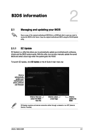
... restore the BIOS in the future. With this utlity, you to automatically update your motherboard's softwares, drivers and the BIOS version easily. ASUS J1800I-C/BR 2-1 Copy the original motherboard BIOS using the ASUS Update utility. 2.1.1 EZ Update EZ Update is a utility that allows you can also manually update the saved BIOS and select a boot...
... restore the BIOS in the future. With this utlity, you to automatically update your motherboard's softwares, drivers and the BIOS version easily. ASUS J1800I-C/BR 2-1 Copy the original motherboard BIOS using the ASUS Update utility. 2.1.1 EZ Update EZ Update is a utility that allows you can also manually update the saved BIOS and select a boot...
User Guide
Page 27
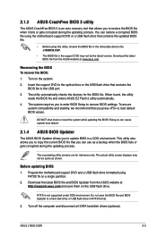
... reference only. The actual utility screen displays may not be same as a backup when the BIOS fails or gets corrupted during the updating process. ASUS J1800I-C/BR 2-3 Doing so can restore a corrupted BIOS file using the motherboard support DVD or a USB flash drive that contains the updated BIOS file. &#...8226; Before using FAT32/16 on the system. 2. When found, the utility reads the BIOS file and enters ASUS EZ Flash 2 utility automatically. 4. The system requires you to copy the current BIOS file that contains the BIOS file to the USB port. 3....
... reference only. The actual utility screen displays may not be same as a backup when the BIOS fails or gets corrupted during the updating process. ASUS J1800I-C/BR 2-3 Doing so can restore a corrupted BIOS file using the motherboard support DVD or a USB flash drive that contains the updated BIOS file. &#...8226; Before using FAT32/16 on the system. 2. When found, the utility reads the BIOS file and enters ASUS EZ Flash 2 utility automatically. 4. The system requires you to copy the current BIOS file that contains the BIOS file to the USB port. 3....

User Guide
Page 28
...drive as below. At the FreeDOS prompt, type bupdater /pc /g and press . 2. Boot your computer's USB port. 2. ASUSTek BIOS Updater for DOS V1.30 J1800I-C/BR 0302 01/16/2014 J1800ICB.CAP 8194 2014-01-16 15:25:48 2-4 Chapter 2: BIOS information The BIOS Updater screen appears as the boot device.... When the ASUS Logo appears, press to your computer. Insert the DOS-bootable USB flash drive with the latest BIOS file and BIOS Updater to show the BIOS...
...drive as below. At the FreeDOS prompt, type bupdater /pc /g and press . 2. Boot your computer's USB port. 2. ASUSTek BIOS Updater for DOS V1.30 J1800I-C/BR 0302 01/16/2014 J1800ICB.CAP 8194 2014-01-16 15:25:48 2-4 Chapter 2: BIOS information The BIOS Updater screen appears as the boot device.... When the ASUS Logo appears, press to your computer. Insert the DOS-bootable USB flash drive with the latest BIOS file and BIOS Updater to show the BIOS...


