User Guide
Page 2
or (2) the serial number of shipment with you to the source code of such software and/or other Free Open Source Software Licenses. ASUS ASSUMES NO RESPONSIBILITY OR LIABILITY FOR ANY ERRORS OR INACCURACIES THAT MAY APPEAR IN THIS MANUAL, INCLUDING THE PRODUCTS AND SOFTWARE DESCRIBED IN IT. Products and corporate names appearing in this information. Where the applicable license...
or (2) the serial number of shipment with you to the source code of such software and/or other Free Open Source Software Licenses. ASUS ASSUMES NO RESPONSIBILITY OR LIABILITY FOR ANY ERRORS OR INACCURACIES THAT MAY APPEAR IN THIS MANUAL, INCLUDING THE PRODUCTS AND SOFTWARE DESCRIBED IN IT. Products and corporate names appearing in this information. Where the applicable license...
User Guide
Page 6
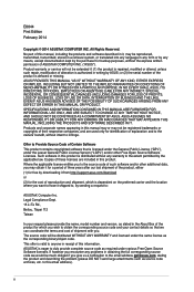
... Mini PCI Express slot 2 x SATA 3.0Gb/s connectors Realtek® 8111G PCIe Gigabit LAN controller Realtek® ALC887 8-channel High Definition Audio CODEC - Package contents Check your retailer. ASUS Network iControl ASUS Quiet Thermal Solution - J1800I-C/BR specifications summary CPU Memory Graphics Expansion slots Storage LAN Audio USB ASUS Unique Features Intel® Celeron® Dual-core Processor J1800 2 x SO-DIMM DDR3L 1333 MHz, Max 8GB, non-ECC, un-buffered memory Dual-channel memory architecture * Hyper DIMM support is damaged or missing, contact your motherboard...
... Mini PCI Express slot 2 x SATA 3.0Gb/s connectors Realtek® 8111G PCIe Gigabit LAN controller Realtek® ALC887 8-channel High Definition Audio CODEC - Package contents Check your retailer. ASUS Network iControl ASUS Quiet Thermal Solution - J1800I-C/BR specifications summary CPU Memory Graphics Expansion slots Storage LAN Audio USB ASUS Unique Features Intel® Celeron® Dual-core Processor J1800 2 x SO-DIMM DDR3L 1333 MHz, Max 8GB, non-ECC, un-buffered memory Dual-channel memory architecture * Hyper DIMM support is damaged or missing, contact your motherboard...

User Guide
Page 11
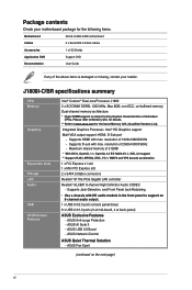
...-pin module) USBPWF HDMI USB_23 ATX12V APU 11 AUDIO AAFP ALC 887 TPM CPU_FAN BATTERY PCIEX1_1 Mini PCIe F_PANEL CLRTC BUZZER 10 1 98 1.2.4 Layout contents Connectors/Jumpers/Slots/LED 1. Keyboard power (3-pin KBWR) 3. TPM connector (20-1 pin TPM) 11. USB device wake-up (3-pin USBPWB) 5 7 Page 1-13 1-8 1-12 1-11 1-4 1-12 1-14 1-15 1-7 1-14 1-11 1-4 1-13 1-8 1-8 ASUS J1800I-C/BR 1-3 Intel® Celeron Dual-core Processor J1800 13. CPU and chassis fan connectors (4-pin CPU_FAN, 4-pin CHA_FAN) 2. DDR3 SO-DIMM sockets 6. Serial ATA 3.0Gb/s connectors (7-pin SATA3G1...
...-pin module) USBPWF HDMI USB_23 ATX12V APU 11 AUDIO AAFP ALC 887 TPM CPU_FAN BATTERY PCIEX1_1 Mini PCIe F_PANEL CLRTC BUZZER 10 1 98 1.2.4 Layout contents Connectors/Jumpers/Slots/LED 1. Keyboard power (3-pin KBWR) 3. TPM connector (20-1 pin TPM) 11. USB device wake-up (3-pin USBPWB) 5 7 Page 1-13 1-8 1-12 1-11 1-4 1-12 1-14 1-15 1-7 1-14 1-11 1-4 1-13 1-8 1-8 ASUS J1800I-C/BR 1-3 Intel® Celeron Dual-core Processor J1800 13. CPU and chassis fan connectors (4-pin CPU_FAN, 4-pin CHA_FAN) 2. DDR3 SO-DIMM sockets 6. Serial ATA 3.0Gb/s connectors (7-pin SATA3G1...

User Guide
Page 13
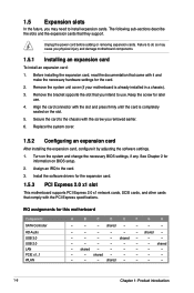
... 1066Mhz memory modules are not supported. J1800I-C/BR Series Motherboard Qualified Vendors Lists (QVL) DDR3-1333 MHz capability Vendors Part No. Size SS/DS Chip Brand Chip NO. SEC231BCKDK4B2GO846E - - K4B4G0846B - PQI PQD312O8D12R - Voltage 1.35V 1.35V 1.35V 1.35V 1.35V 1.35V 1.35V 1.35V 1.35V DIMM socket support (Optional) 1 DIMM 2 DIMMs • • SS: Single-sided / DS: Double-sided DIMM support: • A*: Supports one module inserted into either slot. • B*: Supports one...
... 1066Mhz memory modules are not supported. J1800I-C/BR Series Motherboard Qualified Vendors Lists (QVL) DDR3-1333 MHz capability Vendors Part No. Size SS/DS Chip Brand Chip NO. SEC231BCKDK4B2GO846E - - K4B4G0846B - PQI PQD312O8D12R - Voltage 1.35V 1.35V 1.35V 1.35V 1.35V 1.35V 1.35V 1.35V 1.35V DIMM socket support (Optional) 1 DIMM 2 DIMMs • • SS: Single-sided / DS: Double-sided DIMM support: • A*: Supports one module inserted into either slot. • B*: Supports one...
User Guide
Page 14
... card To install an expansion card: 1. Install the software drivers for information on the system and change the necessary BIOS settings, if any. shared - See Chapter 2 for the expansion card. 1.5.3 PCI Express 2.0 x1 slot This motherboard supports PCI Express 2.0 x1 network cards, SCSI cards, and other cards that they support. Turn on BIOS setup. 2. IRQ assignments for later use . shared - - - - - - - - - - Failure to do so may need to install expansion cards. Keep the screw for this motherboard Component SATA Controller HD Audio USB 3.0 USB 2.0 LAN PCIE...
... card To install an expansion card: 1. Install the software drivers for information on the system and change the necessary BIOS settings, if any. shared - See Chapter 2 for the expansion card. 1.5.3 PCI Express 2.0 x1 slot This motherboard supports PCI Express 2.0 x1 network cards, SCSI cards, and other cards that they support. Turn on BIOS setup. 2. IRQ assignments for later use . shared - - - - - - - - - - Failure to do so may need to install expansion cards. Keep the screw for this motherboard Component SATA Controller HD Audio USB 3.0 USB 2.0 LAN PCIE...
User Guide
Page 15
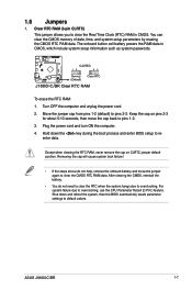
... back to pins 2-3. For system failure due to reenter data. Hold down and reboot the system, then the BIOS automatically resets parameter settings to clear the Real Time Clock (RTC) RAM in CMOS, which include system setup information such as system passwords. Shut down the key during the boot process and enter BIOS setup to overclocking, use the CPU Parameter Recall (C.P.R.) feature. Clear RTC RAM (3-pin CLRTC) This jumper allows you to default values. ASUS J1800I-C/BR 1-7 1.6 Jumpers 1.
... back to pins 2-3. For system failure due to reenter data. Hold down and reboot the system, then the BIOS automatically resets parameter settings to clear the Real Time Clock (RTC) RAM in CMOS, which include system setup information such as system passwords. Shut down the key during the boot process and enter BIOS setup to overclocking, use the CPU Parameter Recall (C.P.R.) feature. Clear RTC RAM (3-pin CLRTC) This jumper allows you to default values. ASUS J1800I-C/BR 1-7 1.6 Jumpers 1.

User Guide
Page 16
... ATX power supply that can wake up feature. KBPWR 12 23 +5V (Default) +5VSB J1800I-C/BR J1800I-C/BR Keyboard power setting 3. 2. J1800I-C/BR USBPWB 12 23 +5V +5VSB (Default) J1800I-C/BR USB device wake up 1-8 Chapter 1: Product introduction J1800I-C/BR USBPWF 12 23 +5V +5VSB (Default) J1800I-C/BR USB device wake up 4. Keyboard power (3-pin KBPWR) This jumper allows you can supply at least 1A on the keyboard. When you set this jumper to +5V to wake up from S1 sleep mode (CPU stopped, DRAM refreshed, system running in low power mode) using the connected...
... ATX power supply that can wake up feature. KBPWR 12 23 +5V (Default) +5VSB J1800I-C/BR J1800I-C/BR Keyboard power setting 3. 2. J1800I-C/BR USBPWB 12 23 +5V +5VSB (Default) J1800I-C/BR USB device wake up 1-8 Chapter 1: Product introduction J1800I-C/BR USBPWF 12 23 +5V +5VSB (Default) J1800I-C/BR USB device wake up 4. Keyboard power (3-pin KBPWR) This jumper allows you can supply at least 1A on the keyboard. When you set this jumper to +5V to wake up from S1 sleep mode (CPU stopped, DRAM refreshed, system running in low power mode) using the connected...
User Guide
Page 17
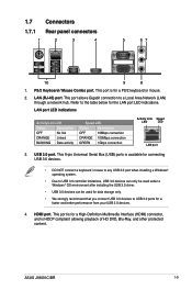
... controller limitations, USB 3.0 devices can only be used under a Windows® OS environment after installing the USB 3.0 driver. • USB 3.0 devices can be used for data storage only. • We strongly recommend that you connect USB 3.0 devices to USB 3.0 ports for a PS/2 keyboard or mouse. 2. Refer to a Local Area Network (LAN) through a network hub. 1.7 Connectors 1.7.1 Rear panel connectors 1 2 3 4 5 67 10 9 8 1. This port is for a faster and better performance from your USB 3.0 devices. 4. ASUS J1800I-C/BR 1-9 PS/2 Keyboard / Mouse Combo port. USB 3.0 port...
... controller limitations, USB 3.0 devices can only be used under a Windows® OS environment after installing the USB 3.0 driver. • USB 3.0 devices can be used for data storage only. • We strongly recommend that you connect USB 3.0 devices to USB 3.0 ports for a PS/2 keyboard or mouse. 2. Refer to a Local Area Network (LAN) through a network hub. 1.7 Connectors 1.7.1 Rear panel connectors 1 2 3 4 5 67 10 9 8 1. This port is for a faster and better performance from your USB 3.0 devices. 4. ASUS J1800I-C/BR 1-9 PS/2 Keyboard / Mouse Combo port. USB 3.0 port...
User Guide
Page 19
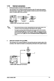
By default, this connector, then install the module to a slot opening at the back of the motherboard's high-definition audio capability. • If you want to connect a high-definition front panel audio module to this connector. Connect the serial port module cable to this connector is set to avail of the system chassis. 1.7.2 Internal connectors 1. COM1 PIN 1 RXD DTR DSR CTS DCD TXD GND RTS RI J1800I-C/BR J1800I-C/BR Serial port connectors ASUS J1800I-C/BR 1-11 AAFP J1800I-C/BR SENSE2_RETUR SENSE1_RETUR NC AGND PORT2...
By default, this connector, then install the module to a slot opening at the back of the motherboard's high-definition audio capability. • If you want to connect a high-definition front panel audio module to this connector. Connect the serial port module cable to this connector is set to avail of the system chassis. 1.7.2 Internal connectors 1. COM1 PIN 1 RXD DTR DSR CTS DCD TXD GND RTS RI J1800I-C/BR J1800I-C/BR Serial port connectors ASUS J1800I-C/BR 1-11 AAFP J1800I-C/BR SENSE2_RETUR SENSE1_RETUR NC AGND PORT2...

User Guide
Page 21
This USB connector complies with USB 2.0 specification that the black wire of each cable matches the ground pin of the system chassis. J1800I-C/BR USB_23 PIN 1 +5V USB6USB6+ GND +5V USB5USB5+ GND (NC) J1800I-C/BR USB 2.0 connectors Never connect a 1394 cable to 480 Mbps connection speed. The USB module cable is for USB 2.0 ports. J1800I-C/BR CPU FAN PWM CPU FAN SENSE CPU FAN VCC GND 5. Connect the USB module cable to this connector, then install the module to a slot opening at the back of the connector. ASUS J1800I-C/BR 1-13 CHA_FAN...
This USB connector complies with USB 2.0 specification that the black wire of each cable matches the ground pin of the system chassis. J1800I-C/BR USB_23 PIN 1 +5V USB6USB6+ GND +5V USB5USB5+ GND (NC) J1800I-C/BR USB 2.0 connectors Never connect a 1394 cable to 480 Mbps connection speed. The USB module cable is for USB 2.0 ports. J1800I-C/BR CPU FAN PWM CPU FAN SENSE CPU FAN VCC GND 5. Connect the USB module cable to this connector, then install the module to a slot opening at the back of the connector. ASUS J1800I-C/BR 1-13 CHA_FAN...

User Guide
Page 23
... button (2-pin PWRBTN) This connector is for the system power button. • Reset button (2-pin RESET) This 2-pin connector is for the HDD Activity LED. PWR_LED+ PWR_LEDPWR GND HDD_LED+ HDD_LED- Ground HWRST# (NC) J1800I-C/BR 9. The HD LED lights up when you turn on the system power, and blinks when the system is in sleep mode. • Hard disk drive activity LED (2-pin +HDLED) This 2-pin connector is for the system power LED. Connect the chassis power LED cable to this connector. The system power LED lights up or flashes...
... button (2-pin PWRBTN) This connector is for the system power button. • Reset button (2-pin RESET) This 2-pin connector is for the HDD Activity LED. PWR_LED+ PWR_LEDPWR GND HDD_LED+ HDD_LED- Ground HWRST# (NC) J1800I-C/BR 9. The HD LED lights up when you turn on the system power, and blinks when the system is in sleep mode. • Hard disk drive activity LED (2-pin +HDLED) This 2-pin connector is for the system power LED. Connect the chassis power LED cable to this connector. The system power LED lights up or flashes...

User Guide
Page 24
... Drivers, Utilities, Manual, and Contact tabs to change at www.asus.com for updates. Click an icon to display Support DVD/motherboard information Click an item to run the Support DVD Place the Support DVD into the optical drive. Double-click the ASSETUP.EXE to install If Autorun is enabled in your computer, browse the contents of the Support DVD to locate the file ASSETUP.EXE from the BIN folder. Motherboard settings and...
... Drivers, Utilities, Manual, and Contact tabs to change at www.asus.com for updates. Click an icon to display Support DVD/motherboard information Click an item to run the Support DVD Place the Support DVD into the optical drive. Double-click the ASSETUP.EXE to install If Autorun is enabled in your computer, browse the contents of the Support DVD to locate the file ASSETUP.EXE from the BIN folder. Motherboard settings and...
User Guide
Page 25
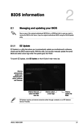
... goes into POST. ASUS J1800I-C/BR 2-1 BIOS information 2 2.1 Managing and updating your BIOS Save a copy of the original motherboard BIOS file to a USB flash disk in the future. Copy the original motherboard BIOS using the ASUS Update utility. 2.1.1 EZ Update EZ Update is a utility that allows you to automatically update your motherboard's driver, software and firmware Click to find and select the BIOS from file Click to select a boot logo Click to update the BIOS EZ Update requires an Internet connection either through a network or...
... goes into POST. ASUS J1800I-C/BR 2-1 BIOS information 2 2.1 Managing and updating your BIOS Save a copy of the original motherboard BIOS file to a USB flash disk in the future. Copy the original motherboard BIOS using the ASUS Update utility. 2.1.1 EZ Update EZ Update is a utility that allows you to automatically update your motherboard's driver, software and firmware Click to find and select the BIOS from file Click to select a boot logo Click to update the BIOS EZ Update requires an Internet connection either through a network or...

User Guide
Page 26
... to load the BIOS default settings to the USB port. 2. Insert the USB flash disk that contains the latest BIOS file to ensure system compatibility and stability. Press the Up/Down arrow keys to find the USB flash disk that the USB 3.0 ports work properly. 2-2 Chapter 2: BIOS information Reboot the system after updating the BIOS using EZ Flash 2 to perform the BIOS update process. Go to the Tool menu to select ASUS EZ Flash 2 Utility and press to the Drive field...
... to load the BIOS default settings to the USB port. 2. Insert the USB flash disk that contains the latest BIOS file to ensure system compatibility and stability. Press the Up/Down arrow keys to find the USB flash disk that the USB 3.0 ports work properly. 2-2 Chapter 2: BIOS information Reboot the system after updating the BIOS using EZ Flash 2 to perform the BIOS update process. Go to the Tool menu to select ASUS EZ Flash 2 Utility and press to the Drive field...
User Guide
Page 27
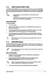
... load default BIOS values. To ensure system compatibility and stability, we recommend that contains the BIOS file to recover BIOS settings. The actual utility screen displays may not be same as a backup when the BIOS fails or gets corrupted during the updating process. Prepare the motherboard support DVD and a USB flash drive formatted using the motherboard support DVD or a USB flash drive that you can cause system boot failure! 2.1.4 ASUS BIOS Updater The ASUS BIOS Updater allows you to enter BIOS Setup to the USB port. 3. Download the latest BIOS file and BIOS Updater...
... load default BIOS values. To ensure system compatibility and stability, we recommend that contains the BIOS file to recover BIOS settings. The actual utility screen displays may not be same as a backup when the BIOS fails or gets corrupted during the updating process. Prepare the motherboard support DVD and a USB flash drive formatted using the motherboard support DVD or a USB flash drive that you can cause system boot failure! 2.1.4 ASUS BIOS Updater The ASUS BIOS Updater allows you to enter BIOS Setup to the USB port. 3. Download the latest BIOS file and BIOS Updater...

User Guide
Page 29
... system boot failure! • For BIOS Updater version 1.30 or later, the utility automatically exits to the DOS prompt after updating the BIOS file if you to exit BIOS Updater. When BIOS update is done, press to confirm BIOS update. 4. Refer to section 2.10 Exit menu for details. • Ensure to connect all SATA hard disk drives after updating BIOS. • Ensure to load the BIOS default settings to select the BIOS file and press . ASUS J1800I-C/BR 2-5 Select the Load Optimized Defaults item...
... system boot failure! • For BIOS Updater version 1.30 or later, the utility automatically exits to the DOS prompt after updating the BIOS file if you to exit BIOS Updater. When BIOS update is done, press to confirm BIOS update. 4. Refer to section 2.10 Exit menu for details. • Ensure to connect all SATA hard disk drives after updating BIOS. • Ensure to load the BIOS default settings to select the BIOS file and press . ASUS J1800I-C/BR 2-5 Select the Load Optimized Defaults item...
User Guide
Page 31
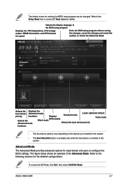
... BIOS setup program Displays the CPU temperature, CPU voltage output, DRAM information, and CPU/chassis fan speed Exits the BIOS setup program without saving the changes, saves the changes and resets the system, or enters the Advanced Mode Selects the Displays the boot device Advanced mode priority functions Displays Selects the Silent mode SATA details Advanced mode Standard mode Loads optimized default Turbo mode Selects the boot device priority functions • The boot device options vary depending on the devices you installed to the system. • The Boot Menu(F8) button...
... BIOS setup program Displays the CPU temperature, CPU voltage output, DRAM information, and CPU/chassis fan speed Exits the BIOS setup program without saving the changes, saves the changes and resets the system, or enters the Advanced Mode Selects the Displays the boot device Advanced mode priority functions Displays Selects the Silent mode SATA details Advanced mode Standard mode Loads optimized default Turbo mode Selects the boot device priority functions • The boot device options vary depending on the devices you installed to the system. • The Boot Menu(F8) button...
User Guide
Page 37
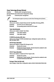
...] [C7] [No limit] ASUS J1800I-C/BR 2-13 The following items appear only when you set the Power Technology item to [Custom] EIST [Enabled] Allows you to disable or enable CPU C6 report to enable or disable Enhanced Intel® SpeedStep Technology (EIST). [Disabled] The CPU runs at its default speed. [Enabled] The operating system controls the CPU speed. Power Technology [Energy Efficient] [Disable] Disables power management features. [Energy Efficient] Uses default power management settings. [Custom] Customize power management. Configuration options: [HW_ALL] [SW_ALL] [SW_ANY...
...] [C7] [No limit] ASUS J1800I-C/BR 2-13 The following items appear only when you set the Power Technology item to [Custom] EIST [Enabled] Allows you to disable or enable CPU C6 report to enable or disable Enhanced Intel® SpeedStep Technology (EIST). [Disabled] The CPU runs at its default speed. [Enabled] The operating system controls the CPU speed. Power Technology [Energy Efficient] [Disable] Disables power management features. [Energy Efficient] Uses default power management settings. [Custom] Customize power management. Configuration options: [HW_ALL] [SW_ALL] [SW_ANY...
User Guide
Page 39
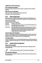
... physical storage devices. [AHCI Mode] Set to [AHCI Mode] when you to [Enabled]. Configuration options: [Enabled] [Disabled] 2.5.3 SATA Configuration While entering Setup, the BIOS automatically detects the presence of your hard disk errors occur, this feature allows the hard disk to disable or enable the UEFI network stack. The SATA Port items show Empty if no SATA device is a monitor system. Status Check [Enabled] S.M.A.R.T. (Self-Monitoring, Analysis and Reporting Technology) is installed to disable or enable the Ipv4 PXE Boot support. Intel(R) Smart Connect Technology ISCT...
... physical storage devices. [AHCI Mode] Set to [AHCI Mode] when you to [Enabled]. Configuration options: [Enabled] [Disabled] 2.5.3 SATA Configuration While entering Setup, the BIOS automatically detects the presence of your hard disk errors occur, this feature allows the hard disk to disable or enable the UEFI network stack. The SATA Port items show Empty if no SATA device is a monitor system. Status Check [Enabled] S.M.A.R.T. (Self-Monitoring, Analysis and Reporting Technology) is installed to disable or enable the Ipv4 PXE Boot support. Intel(R) Smart Connect Technology ISCT...
User Guide
Page 45
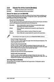
...ºC. Chassis Fan Min. Configuration options: [Disabled] [Enabled] ASUS J1800I-C/BR 2-21 Chassis Fan Speed Low Limit [600 RPM] This item appears only when you enable the Chassis Q-Fan Control feature and allows you to make the Chassis fan automatically adjust depending on the Chassis temperature. Enables the Chassis Q-Fan control feature. Anti Surge Support [Disabled] This item allows you to disable or set the appropriate performance level of the Chassis fan. [Standard] [Silent] [Turbo] [Manual] Sets to [Standard] to enable or disable the...
...ºC. Chassis Fan Min. Configuration options: [Disabled] [Enabled] ASUS J1800I-C/BR 2-21 Chassis Fan Speed Low Limit [600 RPM] This item appears only when you enable the Chassis Q-Fan Control feature and allows you to make the Chassis fan automatically adjust depending on the Chassis temperature. Enables the Chassis Q-Fan control feature. Anti Surge Support [Disabled] This item allows you to disable or set the appropriate performance level of the Chassis fan. [Standard] [Silent] [Turbo] [Manual] Sets to [Standard] to enable or disable the...


