
User Manual
Page 3
... 2-2 2.3 Removing the side cover and front panel assembly 2-3 2.4 Central Processing Unit (CPU 2-4 2.4.1 Overview 2-4 2.4.2 Installing CPU 2-4 2.4.3 Installing the CPU fan and heatsink assembly 2-6 2.5 Installing a DIMM 2-8 2.5.1 Overview 2-8 2.5.2 Memory configurations 2-9 2.5.3 Installing a DDR2 DIMM 2-15 2.5.4 Removing a DDR2 DIMM 2-15 2.6 Expansion slots 2-16 2.6.1 PCI slots 2-16 2.6.2 PCI Express x1 slot 2-16 2.6.3 PCI Express x16 slot 2-16...
... 2-2 2.3 Removing the side cover and front panel assembly 2-3 2.4 Central Processing Unit (CPU 2-4 2.4.1 Overview 2-4 2.4.2 Installing CPU 2-4 2.4.3 Installing the CPU fan and heatsink assembly 2-6 2.5 Installing a DIMM 2-8 2.5.1 Overview 2-8 2.5.2 Memory configurations 2-9 2.5.3 Installing a DDR2 DIMM 2-15 2.5.4 Removing a DDR2 DIMM 2-15 2.6 Expansion slots 2-16 2.6.1 PCI slots 2-16 2.6.2 PCI Express x1 slot 2-16 2.6.3 PCI Express x16 slot 2-16...
User Manual
Page 12
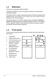
...™ card slot 8. USB 2.0 ports 1-2 Chapter 1: System introduction Thank you ahead in -one barebone system with a versatile home entertainment feature. The ASUS G1-P5G43 is an all-in the world of system memory using DDR2-1066/800/667 DIMMs. High-resolution graphics via integrated graphics controller or PCI Express x16 slot, Serial ATA, USB...
...™ card slot 8. USB 2.0 ports 1-2 Chapter 1: System introduction Thank you ahead in -one barebone system with a versatile home entertainment feature. The ASUS G1-P5G43 is an all-in the world of system memory using DDR2-1066/800/667 DIMMs. High-resolution graphics via integrated graphics controller or PCI Express x16 slot, Serial ATA, USB...

User Manual
Page 18
Basic components to indicate that the standby power LED is ON, in sleep mode or in the system. Hard disk drive 5. DDR2 Dual Inline Memory Module (DIMM) 3. 2.1 Preparation Before you proceed, make sure that the system is OFF before handling components to avoid damaging them due to static electricity. • ...
Basic components to indicate that the standby power LED is ON, in sleep mode or in the system. Hard disk drive 5. DDR2 Dual Inline Memory Module (DIMM) 3. 2.1 Preparation Before you proceed, make sure that the system is OFF before handling components to avoid damaging them due to static electricity. • ...

User Manual
Page 24
...;a�ll�in��g�a� �D�IM�M� 2.5.1 Overview The motherboard comes with four Double Data Rate 2 (DDR2) Dual Inline Memory Modules (DIMM) sockets. The figure illustrates the location of the DDR2 DIMM sockets: Channel Channel A Channel B Sockets DIMM_A1 and DIMM_A2 DIMM_B1 and DIMM_B2 2-8 Chapter 2: Basic...
...;a�ll�in��g�a� �D�IM�M� 2.5.1 Overview The motherboard comes with four Double Data Rate 2 (DDR2) Dual Inline Memory Modules (DIMM) sockets. The figure illustrates the location of the DDR2 DIMM sockets: Channel Channel A Channel B Sockets DIMM_A1 and DIMM_A2 DIMM_B1 and DIMM_B2 2-8 Chapter 2: Basic...
User Manual
Page 25
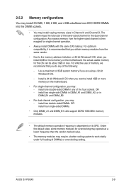
...-bit Windows® OS when you want to install 4GB or more memory on the motherboard, the actual usable memory for single-channel operation. • Always install DIMMs with the same CAS latency. ASUS G1-P5G43 2-9 install two single-side DIMMs in DIMM_A1 and DIMM_A2, or in ...DIMM_B1 and DIMM_B2. • For dual-channel configuration, you may : - Under the default state, some memory modules for the dual-channel configuration. 2.5.2 Memory configurations You may install 512 MB...
...-bit Windows® OS when you want to install 4GB or more memory on the motherboard, the actual usable memory for single-channel operation. • Always install DIMMs with the same CAS latency. ASUS G1-P5G43 2-9 install two single-side DIMMs in DIMM_A1 and DIMM_A2, or in ...DIMM_B1 and DIMM_B2. • For dual-channel configuration, you may : - Under the default state, some memory modules for the dual-channel configuration. 2.5.2 Memory configurations You may install 512 MB...

User Manual
Page 30
.... • C*: Supports four modules inserted into both the yellow and black slots as two pairs of Dual-channel memory configuration. DS MDT 18D51201D-30726E DS MDT 18D51280D-30646E SS takeMS MS18T51280-3S0627D SS takeMS MS18T51280-3 DS takeMS MS18T51280-3SEA07100 DS takeMS MS18T51280-3SP0717A DS ... TMS1GB264C081-665QI TVDD1.02M667C4 D46701GP3-63BJU D46702GP0-73BCU Size 512MB 1024MB 512MB 512MB 1024MB 1024MB 1024MB 1024MB 1024MB 2048MB SS/ DS Brand ChipNO. Visit the ASUS website at http://support.asus.com for the latest QVL. 2-14 Chapter 2: Basic installation
.... • C*: Supports four modules inserted into both the yellow and black slots as two pairs of Dual-channel memory configuration. DS MDT 18D51201D-30726E DS MDT 18D51280D-30646E SS takeMS MS18T51280-3S0627D SS takeMS MS18T51280-3 DS takeMS MS18T51280-3SEA07100 DS takeMS MS18T51280-3SP0717A DS ... TMS1GB264C081-665QI TVDD1.02M667C4 D46701GP3-63BJU D46702GP0-73BCU Size 512MB 1024MB 512MB 512MB 1024MB 1024MB 1024MB 1024MB 1024MB 2048MB SS/ DS Brand ChipNO. Visit the ASUS website at http://support.asus.com for the latest QVL. 2-14 Chapter 2: Basic installation
User Manual
Page 45
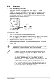
..., then the BIOS automatically resets parameter settings to default values. • Due to the chipset limitation, AC power off and on CLRTC jumper default position. ASUS G1-P5G43 4-3 Removing the cap will cause system boot failure! • If the steps above do not need to clear the RTC when the system hangs due... to overclocking, use the C.P.R. function. Clear RTC RAM (3-pin CLRTC) This jumper allows you use the CPU Parameter Recall (C.P.R.) feature. You can clear the CMOS memory of date, time, and system setup parameters by erasing the CMOS RTC RAM data.
..., then the BIOS automatically resets parameter settings to default values. • Due to the chipset limitation, AC power off and on CLRTC jumper default position. ASUS G1-P5G43 4-3 Removing the cap will cause system boot failure! • If the steps above do not need to clear the RTC when the system hangs due... to overclocking, use the C.P.R. function. Clear RTC RAM (3-pin CLRTC) This jumper allows you use the CPU Parameter Recall (C.P.R.) feature. You can clear the CMOS memory of date, time, and system setup parameters by erasing the CMOS RTC RAM data.

User Manual
Page 64
... an overview of the general system specifications. Bios Information Displays the auto-detected BIOS information. Processor Displays the auto-detected CPU specification. System Memory Displays the auto-detected system memory. 5-10 Chapter 5: BIOS setup Due to Intel chipset driver support regulation, the AHCI mode is not supported in this menu. This will...
... an overview of the general system specifications. Bios Information Displays the auto-detected BIOS information. Processor Displays the auto-detected CPU specification. System Memory Displays the auto-detected system memory. 5-10 Chapter 5: BIOS setup Due to Intel chipset driver support regulation, the AHCI mode is not supported in this menu. This will...
User Manual
Page 66
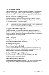
...] [Disabled] 5.4.2 Chipset The Chipset menu allows you to change the advanced chipset settings. North Bridge Configuration Memory Remap Feature [Enabled] Allows you to enabled or disable the remapping of the overlapped PCI memory above the total physical memory. Configuration options: [Disabled] [Enabled] The following item appears only when you install 64-bit operating...
...] [Disabled] 5.4.2 Chipset The Chipset menu allows you to change the advanced chipset settings. North Bridge Configuration Memory Remap Feature [Enabled] Allows you to enabled or disable the remapping of the overlapped PCI memory above the total physical memory. Configuration options: [Disabled] [Enabled] The following item appears only when you install 64-bit operating...
User Manual
Page 67
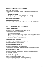
Configuration options: [Disabled] [Enabled, 32MB] [Enabled, 64MB] [Enabled, 128MB] DVMT Memory [256MB] Configuration options: [128MB] [256MB] [Maximum DVMT] South Bridge Configuration Audio Controller [Disabled] Allows you to set to Enabled. Configuration options: [... base address. This item appears only when the Onboard LAN item is set the audio controller. Configuration options: [Normal] [Bi-Directional] [EPP] [ECP] ASUS G1-P5G43 5-13 Configuration options: [Disabled] [378] [278] [3BC] Parallel Port Mode [ECP] Allows you to select the Parallel Port mode. IGD Graphics Mode...
Configuration options: [Disabled] [Enabled, 32MB] [Enabled, 64MB] [Enabled, 128MB] DVMT Memory [256MB] Configuration options: [128MB] [256MB] [Maximum DVMT] South Bridge Configuration Audio Controller [Disabled] Allows you to set to Enabled. Configuration options: [... base address. This item appears only when the Onboard LAN item is set the audio controller. Configuration options: [Normal] [Bi-Directional] [EPP] [ECP] ASUS G1-P5G43 5-13 Configuration options: [Disabled] [378] [278] [3BC] Parallel Port Mode [ECP] Allows you to select the Parallel Port mode. IGD Graphics Mode...
User Manual
Page 69
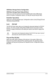
.... The menu includes setting IRQ and DMA channel resources for either PCI/PnP or legacy ISA devices, and setting the memory size block for PCI/PnP devices. Configuration options: [No] [Yes] ASUS G1-P5G43 5-15 USB Mass Storage Device Configuration USB Mass Storage Reset Delay [20 Sec] Allows you to set the maximum time...
.... The menu includes setting IRQ and DMA channel resources for either PCI/PnP or legacy ISA devices, and setting the memory size block for PCI/PnP devices. Configuration options: [No] [Yes] ASUS G1-P5G43 5-15 USB Mass Storage Device Configuration USB Mass Storage Reset Delay [20 Sec] Allows you to set the maximum time...

