Asus G1-P7P55E Support and Manuals
Get Help and Manuals for this Asus item

View All Support Options Below
Free Asus G1-P7P55E manuals!
Problems with Asus G1-P7P55E?
Ask a Question
Free Asus G1-P7P55E manuals!
Problems with Asus G1-P7P55E?
Ask a Question
Popular Asus G1-P7P55E Manual Pages
User Manual - Page 7

... 1 LASER PRODUCT
DO NOT throw the desktop PC's components in municipal waste.
How this guide
Audience
This guide provides general information and installation instructions about the ASUS G1-P7P55E barebone system. VORSICHT: Explosionsgetahr bei unsachgemäßen Austausch der Batterie. This symbol of the crossed out wheeled bin indicates that the product (electrical and electronic...
User Manual - Page 9

Support DVD
4. Installation guide
ix
ASUS G1-P7P55E barebone system with
• ASUS motherboard
• Power supply unit
• ASUS chassis
2.
System package contents
Check your G1-P7P55E system package for the following items. If any of the items is damaged or missing, contact your retailer immediately. Cables
• AC power cable • ...
User Manual - Page 12
...
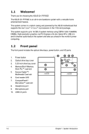
3. 5.25-inch drive bay cover
2
4. Card reader LED
7. The ASUS G1-P7P55E is an all-in the 1156-land package. The system comes in a stylish casing and powered by the ASUS motherboard that supports the Intel® Core™ i7/ Core™ i5 processors in -one barebone system with a versatile home entertainment feature.
Microphone port
10.
User Manual - Page 13
...
16
13
17
14
15
18
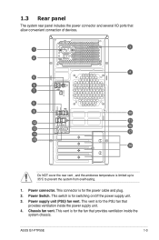
Do NOT cover the rear vent , and the ambience temperature is for the power cable and plug. 2. Power Switch. ASUS G1-P7P55E
1-3 Chassis fan vent.
User Manual - Page 15

...Black Gray
Headset. 2-channel Line In Line Out Mic In - - -
4-channel
Line In Front Speaker Out Mic In - Rear Speaker Out -
6-channel
Line In Front Speaker Out Mic In Center/Subwoofer Rear Speaker Out -
8-channel
Line In Front Speaker Out Mic In Center/Subwoofer Rear Speaker Out Side Speaker Out
18.
ASUS G1-P7P55E...
1-5
Remove these covers when installing expansion...
User Manual - Page 27

... 1.65-1.85V
1.60V 1.5V
1.8V
1.8V 1.8V
1.5~1.6V 1.5~1.6V
1.5-1.6V 1.5~1.6V 1.5V~1.6V 1.5V 1.5V
1.5V ± 0.075V
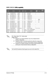
DIMM Support A* B* C
ASUS G1-P7P55E
2-11 Size
SS/ DS
Brand
Chip NO. DDR3-1333MHz capability
Vendor
Part No. Under the default state, some memory modules for overclocking may operate at a lower frequency than the vendor-marked value...
User Manual - Page 29
...;•
OCZ
OCZ3SOE10662GK
2048MB(Kit of Dual-channel memory configuration. Single-sided / DS -
ASUS G1-P7P55E
2-13
Visit the ASUS website at http://support.asus.com for the latest QVL. DDR3 1067(O.C.)�M�H��z�c�a�p��a�b�i�li�ty�
Vendor
Part No. Size
SS/ DS
Brand
Chip NO.
User Manual - Page 31

... that comply with the PCI Express specifications. ASUS G1-P7P55E
2-15 The figure shows a network card installed on the PCI Express x16 slot. The figure shows a graphics card installed on the PCI Express x1 slot.
2.6.3 PCI Express x16 slots
This motherboard supports PCI Express x16 graphic cards that they support. Make sure to install expansion cards. 2.6 Expansion slots
In...
User Manual - Page 33

....
3
3. 2.7 Installing storage drives
2.7.1 Installing an optical drive
1.
SATA
4
For IDE HDD: Connect the IDE signal and power plugs to the connectors at the back of the drive.
2.7.2 Installing a hard disk drive
1. SATA
4
For IDE ODD: Connect the IDE signal and power plugs to the connectors at the back of the drive.
2 3
IDE
3 IDE
ASUS G1-P7P55E...
User Manual - Page 37

... display support DVD/motherboard information
Click an item to install
If Autorun is enabled in your system from the BIN folder. Intel Chipset Driver Installs the Intel® chipset driver.
ASUS G1-P7P55E
3-3
ASUS InstAll Launches the ASUS InstAll driver installation wizard. Realtek Audio Driver Installs the Realtek audio driver and application. ASUS EPU-4 Engine Installs the ASUS...
User Manual - Page 39

ASUS G1-P7P55E
3-5 3.3.3 Make disk menu
The Make Disk menu allows you to make a AHCI/RAID driver disk.
3.3.4 ASUS Contact information
Click the Contact tab to display the ASUS contact information.
You can also find this information on the inside front cover of this user guide.
User Manual - Page 41

Filelist
Displays the contents of the support DVD and a brief description of each in text format. ASUS G1-P7P55E
3-7
User Manual - Page 44

... in CMOS. ASUS G1-P7P55E
4-3 Keep the cap on CLRTC jumper default position. function. Except when clearing the RTC RAM, never remove the cap on pins 2-3 for about 5-10 seconds, then move the jumper again to clear the Real Time Clock (RTC) RAM in CMOS, which include system setup information such as system passwords.
4.3 Jumpers...
User Manual - Page 46

...you use a PSU with a higher power output when configuring a system with ATX 12 V Specification 2.0 (or later version) and provides a minimum power of the system chassis.
+5V ...system, we recommend that you use a power supply unit (PSU) that you intend to install additional devices.
ASUS G1-P7P55E
4-5 ATX power connectors (24-pin EATXPWR, 4-pin ATX12V)
These connectors are designed to...
User Manual - Page 48

These USB connectors comply with USB 2.0 specification that supports up to the USB connectors. Doing so will damage the motherboard!...the system chassis. P7P55-M_DP
TPA1GND TPB1+12V GND
IE1394_1
1
TPA1+ GND
TPB1+ +12V
P7P55-M_DP IEEE 1394a connector
ASUS G1-P7P55E
4-7 6. USB connectors (10-1 pin USB78, USB910, USB1112, USB1314)
These connectors are for an IEEE1394a port.
The USB...
Asus G1-P7P55E Reviews
We have not received any reviews for Asus yet.