User Manual
Page 7
... has been designed to the manufacturer's instructions. How this guide Audience This guide provides general information and installation instructions about the ASUS G1-P5G43 barebone system. Lithium-Ion Battery Warning CAUTION: Danger of explosion if battery is organized This guide contains the following parts: ... NOT throw the mercury-containing button cell battery in municipal waste. This guide is intended for disposal of the ASUS G1-P5G43. About this guide is incorrectly replaced. The chapter lists the system features, including introduction on the front and rear panel,...
... has been designed to the manufacturer's instructions. How this guide Audience This guide provides general information and installation instructions about the ASUS G1-P5G43 barebone system. Lithium-Ion Battery Warning CAUTION: Danger of explosion if battery is organized This guide contains the following parts: ... NOT throw the mercury-containing button cell battery in municipal waste. This guide is intended for disposal of the ASUS G1-P5G43. About this guide is incorrectly replaced. The chapter lists the system features, including introduction on the front and rear panel,...
User Manual
Page 9
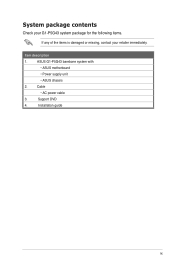
Cable • AC power cable 3. Support DVD 4. Installation guide ix ASUS G1-P5G43 barebone system with • ASUS motherboard • Power supply unit • ASUS chassis 2. System package contents Check your G1-P5G43 system package for the following items. If any of the items is damaged or missing, contact your retailer immediately. Item description 1.
Cable • AC power cable 3. Support DVD 4. Installation guide ix ASUS G1-P5G43 barebone system with • ASUS motherboard • Power supply unit • ASUS chassis 2. System package contents Check your G1-P5G43 system package for the following items. If any of the items is damaged or missing, contact your retailer immediately. Item description 1.
User Manual
Page 11
System introduction Chapter 1 This chapter gives a general description of the ASUS G1-P5G43. The chapter lists the system features including introduction on the front and rear panel, and internal components.
System introduction Chapter 1 This chapter gives a general description of the ASUS G1-P5G43. The chapter lists the system features including introduction on the front and rear panel, and internal components.
User Manual
Page 12
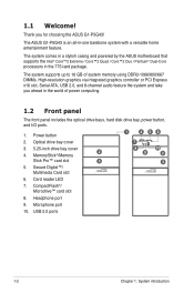
... controller or PCI Express x16 slot, Serial ATA, USB 2.0, and 8-channel audio feature the system and take you for choosing the ASUS G1-P5G43! MemoryStick®/Memory Stick Pro™ card slot 3 5. The system supports up to 16 GB of power computing. 1.2 Front ...; card slot 8. Headphone port 9. Card reader LED 7. Optical drive bay cover 7 3. 5.25-inch drive bay cover 2 4. 1.1 Welcome! The ASUS G1-P5G43 is an all-in-one barebone system with a versatile home entertainment feature. Power button 1 4 56 2. Secure Digital™/ Multimedia Card slot 8 9 10 2 3 6.
... controller or PCI Express x16 slot, Serial ATA, USB 2.0, and 8-channel audio feature the system and take you for choosing the ASUS G1-P5G43! MemoryStick®/Memory Stick Pro™ card slot 3 5. The system supports up to 16 GB of power computing. 1.2 Front ...; card slot 8. Headphone port 9. Card reader LED 7. Optical drive bay cover 7 3. 5.25-inch drive bay cover 2 4. 1.1 Welcome! The ASUS G1-P5G43 is an all-in-one barebone system with a versatile home entertainment feature. Power button 1 4 56 2. Secure Digital™/ Multimedia Card slot 8 9 10 2 3 6.
User Manual
Page 13
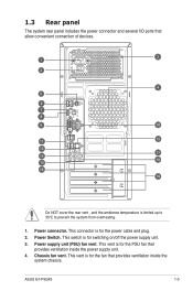
... ventilation inside the system chassis. Chassis fan vent. Power Switch. Power supply unit (PSU) fan vent. This vent is for the power cable and plug. 2. ASUS G1-P5G43 1-3 Power connector. 1.3 Rear panel The system rear panel includes the power connector and several I/O ports that provides ventilation inside the power supply unit. 4. This vent...
... ventilation inside the system chassis. Chassis fan vent. Power Switch. Power supply unit (PSU) fan vent. This vent is for the power cable and plug. 2. ASUS G1-P5G43 1-3 Power connector. 1.3 Rear panel The system rear panel includes the power connector and several I/O ports that provides ventilation inside the power supply unit. 4. This vent...
User Manual
Page 15
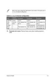
Remove these covers when installing expansion cards. ASUS G1-P5G43 1-5 Audio 2, 4, 6, or 8-channel configuration Port Light Blue Lime Pink Orange Black Gray Headset. 2-channel Line In Line Out Mic In - - - 4-channel Line In Front Speaker ...
Remove these covers when installing expansion cards. ASUS G1-P5G43 1-5 Audio 2, 4, 6, or 8-channel configuration Port Light Blue Lime Pink Orange Black Gray Headset. 2-channel Line In Line Out Mic In - - - 4-channel Line In Front Speaker ...
User Manual
Page 19
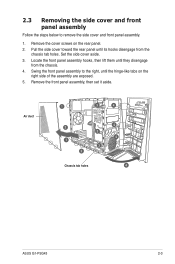
... the side cover aside. 3. Pull the side cover toward the rear panel until they disengage from the chassis tab holes. Air duct 1 3 4 2 3 1 3 2 Chassis tab holes 4 4 4 ASUS G1-P5G43 2-3 Swing the front panel assembly to remove the side cover and front panel assembly. 1. 2.3 Removing the side cover and front panel assembly Follow the steps...
... the side cover aside. 3. Pull the side cover toward the rear panel until they disengage from the chassis tab holes. Air duct 1 3 4 2 3 1 3 2 Chassis tab holes 4 4 4 ASUS G1-P5G43 2-3 Swing the front panel assembly to remove the side cover and front panel assembly. 1. 2.3 Removing the side cover and front panel assembly Follow the steps...
User Manual
Page 21
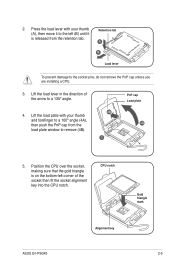
... plate with your thumb and forefinger to a 100º angle (4A), then push the PnP cap from the retention tab. CPU notch Gold triangle mark ASUS G1-P5G43 Alignment key 2-5 Lift the load lever in the direction of the socket then fit the socket alignment key into the CPU notch. Position the CPU...
... plate with your thumb and forefinger to a 100º angle (4A), then push the PnP cap from the retention tab. CPU notch Gold triangle mark ASUS G1-P5G43 Alignment key 2-5 Lift the load lever in the direction of the socket then fit the socket alignment key into the CPU notch. Position the CPU...
User Manual
Page 23
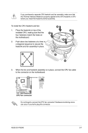
... not forget to plug this connector. Place the heatsink on top of the installed CPU, making sure that the Thermal Interface Material is in place. ASUS G1-P5G43 2-7 Push down two fasteners at a time in a diagonal sequence to secure the heatsink and fan assembly in place, connect the CPU fan cable to the...
... not forget to plug this connector. Place the heatsink on top of the installed CPU, making sure that the Thermal Interface Material is in place. ASUS G1-P5G43 2-7 Push down two fasteners at a time in a diagonal sequence to secure the heatsink and fan assembly in place, connect the CPU fan cable to the...
User Manual
Page 25
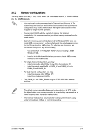
...-sized channel for the OS can be about 3GB or less. install two single-side DIMMs in DIMM_A1 and DIMM_A2, or in Channel A and Channel B. ASUS G1-P5G43 2-9 For optimum compatibility, it is then mapped for overclocking may operate at a lower frequency than the vendor-marked value. • The memory modules may : - The...
...-sized channel for the OS can be about 3GB or less. install two single-side DIMMs in DIMM_A1 and DIMM_A2, or in Channel A and Channel B. ASUS G1-P5G43 2-9 For optimum compatibility, it is then mapped for overclocking may operate at a lower frequency than the vendor-marked value. • The memory modules may : - The...
User Manual
Page 29
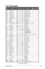
...; KINGBOX DDRII1G667MHz 1024MB DS KINGBOX EPD264082200-4 • •• Leadmax LRMP512U64A8-Y5 1024MB DS Hynix HY5PS12821CFP-Y5C702AA 5 • •• (continued on the next page) ASUS G1-P5G43 2-13 Size SS/ DS Brand ChipNO. DDR2 667�M�H��z�c�a�p��a�b�i�li�ty� Vendor...
...; KINGBOX DDRII1G667MHz 1024MB DS KINGBOX EPD264082200-4 • •• Leadmax LRMP512U64A8-Y5 1024MB DS Hynix HY5PS12821CFP-Y5C702AA 5 • •• (continued on the next page) ASUS G1-P5G43 2-13 Size SS/ DS Brand ChipNO. DDR2 667�M�H��z�c�a�p��a�b�i�li�ty� Vendor...
User Manual
Page 31
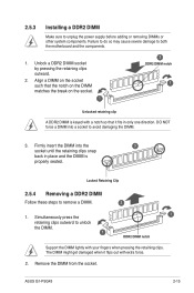
... steps to avoid damaging the DIMM. 3. Remove the DIMM from the socket. Align a DIMM on the socket such that it flips out with extra force. 2. ASUS G1-P5G43 2-15 Firmly insert the DIMM into a socket to remove a DIMM. 2 1. Simultaneously press the 1 retaining clips outward to unlock the DIMM. 1 DDR2 DIMM notch Support the...
... steps to avoid damaging the DIMM. 3. Remove the DIMM from the socket. Align a DIMM on the socket such that it flips out with extra force. 2. ASUS G1-P5G43 2-15 Firmly insert the DIMM into a socket to remove a DIMM. 2 1. Simultaneously press the 1 retaining clips outward to unlock the DIMM. 1 DDR2 DIMM notch Support the...
User Manual
Page 33
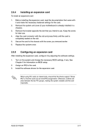
... the card. 3. Turn on the slot. 5. See Chapter 5 for the card. 2. Install the software drivers for later use . When using PCI cards on BIOS setup. 2. ASUS G1-P5G43 2-17
... the card. 3. Turn on the slot. 5. See Chapter 5 for the card. 2. Install the software drivers for later use . When using PCI cards on BIOS setup. 2. ASUS G1-P5G43 2-17
User Manual
Page 35
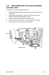
... chassis tab holes . 4. 2.8 Reinstalling the front panel assembly and side cover To reinstall the front panel assembly and side cover: 1. Air duct 5 2 4 2 5 2 3 Chassis tab holes 1 1 1 2 ASUS G1-P5G43 2-19 Push the side cover to the direction of the chassis. 2. Swing the front panel assembly to the left, then insert the hooks to the...
... chassis tab holes . 4. 2.8 Reinstalling the front panel assembly and side cover To reinstall the front panel assembly and side cover: 1. Air duct 5 2 4 2 5 2 3 Chassis tab holes 1 1 1 2 ASUS G1-P5G43 2-19 Push the side cover to the direction of the chassis. 2. Swing the front panel assembly to the left, then insert the hooks to the...
User Manual
Page 39
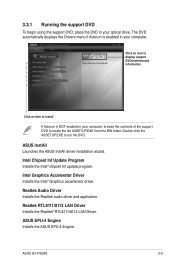
...support DVD to run the DVD. ASUS InstAll Launches the ASUS InstAll driver installation wizard. Click an icon to display support DVD/motherboard information Click an item to install If Autorun is enabled in your optical drive. ASUS G1-P5G43 3-3 Realtek RTL8111/8112 LAN Driver ...Installs the Realtek® RTL8111/8112 LAN Driver. Realtek Audio Driver Installs the Realtek audio driver and application. ASUS EPU-4 Engine Installs the ASUS EPU-4 Engine. 3.3.1 Running the support DVD...
...support DVD to run the DVD. ASUS InstAll Launches the ASUS InstAll driver installation wizard. Click an icon to display support DVD/motherboard information Click an item to install If Autorun is enabled in your optical drive. ASUS G1-P5G43 3-3 Realtek RTL8111/8112 LAN Driver ...Installs the Realtek® RTL8111/8112 LAN Driver. Realtek Audio Driver Installs the Realtek audio driver and application. ASUS EPU-4 Engine Installs the ASUS EPU-4 Engine. 3.3.1 Running the support DVD...
User Manual
Page 41
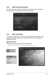
3.3.3 ASUS Contact information Click the Contact tab to display the specified information. Click an icon to display the ASUS contact information. ASUSTeK Computer INC. Motherboard Info Displays the general specifications of the support DVD. G1-P5G43 Rev X.0x American Megatrends Inc. 0205 08/13/2009 1024 KBytes ASUS G1-P5G43 3-5 You can also find this information on the inside front cover of this user guide. 3.3.4 Other information The icons on the top right corner of the screen give additional information on the motherboard and the contents of the motherboard.
3.3.3 ASUS Contact information Click the Contact tab to display the specified information. Click an icon to display the ASUS contact information. ASUSTeK Computer INC. Motherboard Info Displays the general specifications of the support DVD. G1-P5G43 Rev X.0x American Megatrends Inc. 0205 08/13/2009 1024 KBytes ASUS G1-P5G43 3-5 You can also find this information on the inside front cover of this user guide. 3.3.4 Other information The icons on the top right corner of the screen give additional information on the motherboard and the contents of the motherboard.
User Manual
Page 45
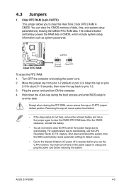
... the computer and unplug the power cord. 2. Plug the power cord and turn off is required before rebooting the system. To erase the RTC RAM: 1. ASUS G1-P5G43 4-3 4.3 Jumpers 1. You can clear the CMOS memory of date, time, and system setup parameters by erasing the CMOS RTC RAM data. Shut down the key...
... the computer and unplug the power cord. 2. Plug the power cord and turn off is required before rebooting the system. To erase the RTC RAM: 1. ASUS G1-P5G43 4-3 4.3 Jumpers 1. You can clear the CMOS memory of date, time, and system setup parameters by erasing the CMOS RTC RAM data. Shut down the key...
User Manual
Page 47
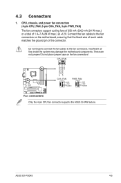
.... Do not place jumper caps on the motherboard, ensuring that the black wire of each cable matches the ground pin of 1 A~7 A (84 W max.) at +12V. ASUS G1-P5G43 4-5 CPU, chassis, and power fan connectors. (4-pin CPU_FAN, 3-pin CHA_FAN, 3-pin PWR_FAN) The fan connectors support cooling fans of 350 mA~2000 mA (24 W max....) or a total of the connector. These are not jumpers! Connect the fan cables to the fan connectors. Only the 4-pin CPU fan connector supports the ASUS Q-FAN feature. Do not forget to connect the fan cables to the fan connectors on the fan connectors!
.... Do not place jumper caps on the motherboard, ensuring that the black wire of each cable matches the ground pin of 1 A~7 A (84 W max.) at +12V. ASUS G1-P5G43 4-5 CPU, chassis, and power fan connectors. (4-pin CPU_FAN, 3-pin CHA_FAN, 3-pin PWR_FAN) The fan connectors support cooling fans of 350 mA~2000 mA (24 W max....) or a total of the connector. These are not jumpers! Connect the fan cables to the fan connectors. Only the 4-pin CPU fan connector supports the ASUS Q-FAN feature. Do not forget to connect the fan cables to the fan connectors on the fan connectors!
User Manual
Page 49
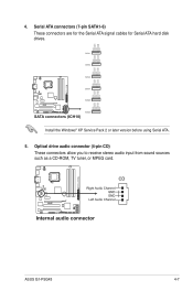
Install the Windows® XP Service Pack 2 or later version before using Serial ATA. 5. Serial ATA connectors (7-pin SATA1-6) These connectors are for the Serial ATA signal cables for Serial ATA hard disk drives. 4. ASUS G1-P5G43 4-7 Optical drive audio connector (4-pin CD) These connectors allow you to receive stereo audio input from sound sources such as a CD-ROM, TV tuner, or MPEG card.
Install the Windows® XP Service Pack 2 or later version before using Serial ATA. 5. Serial ATA connectors (7-pin SATA1-6) These connectors are for the Serial ATA signal cables for Serial ATA hard disk drives. 4. ASUS G1-P5G43 4-7 Optical drive audio connector (4-pin CD) These connectors allow you to receive stereo audio input from sound sources such as a CD-ROM, TV tuner, or MPEG card.

User Manual
Page 51
... for the system power button. Pressing the power button turns the system on the BIOS settings. Connect the chassis power LED cable to this connector. ASUS G1-P5G43 4-9
... for the system power button. Pressing the power button turns the system on the BIOS settings. Connect the chassis power LED cable to this connector. ASUS G1-P5G43 4-9


