F2A55 User's Manual
Page 12
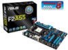
... PCIEX16_2 AMD® A55 ALC 887 SPDIF_OUT AAFP PCI2 64Mb BIOS PCI3 COM CLRTC USB78 USB910 SATA3G_1 SATA3G_2 SATA3G_3 SATA3G_4 SB_PWR USB1112 PANEL SATA3G_5 SATA3G_6 ASUS F2A55 motherboard User Guide 2 x Serial ATA 3.0 Gb/s cables 1 x I/O Shield User Guide Support DVD • If any of the above are for the following items. SOCKET FM2...
... PCIEX16_2 AMD® A55 ALC 887 SPDIF_OUT AAFP PCI2 64Mb BIOS PCI3 COM CLRTC USB78 USB910 SATA3G_1 SATA3G_2 SATA3G_3 SATA3G_4 SB_PWR USB1112 PANEL SATA3G_5 SATA3G_6 ASUS F2A55 motherboard User Guide 2 x Serial ATA 3.0 Gb/s cables 1 x I/O Shield User Guide Support DVD • If any of the above are for the following items. SOCKET FM2...
F2A55 User's Manual
Page 13
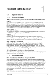
..., improved lifespan, and enhanced thermal capacity. 1.1.2 ASUS DIGI+ VRM DIGI+ Power Control: Digital Power Design for the APU* ASUS motherboards using user-defined profiles. Engineered and tested to assure unmitigated performance, ASUS A55 boards with DIGI+ VRM remain efficient and accurate... combines processing power and advanced DirectX 11 graphics in FM2 socket compatible CPUs ASUS F2A55 1-1 The effect is adjusted via either carefully developed automated modes, or by world-renowned ASUS quality, it creates an ideal computing platform for reliable application in every scenario...
..., improved lifespan, and enhanced thermal capacity. 1.1.2 ASUS DIGI+ VRM DIGI+ Power Control: Digital Power Design for the APU* ASUS motherboards using user-defined profiles. Engineered and tested to assure unmitigated performance, ASUS A55 boards with DIGI+ VRM remain efficient and accurate... combines processing power and advanced DirectX 11 graphics in FM2 socket compatible CPUs ASUS F2A55 1-1 The effect is adjusted via either carefully developed automated modes, or by world-renowned ASUS quality, it creates an ideal computing platform for reliable application in every scenario...
F2A55 User's Manual
Page 15
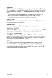
...new level of the product and thus mitigate environmental impacts. With its easy and user-friendly interface, you to overclocking failure. ASUS CrashFree BIOS 3 ASUS CrashFree BIOS 3 is European Union´s Energy-related Products (ErP) ready, and ErP requires products to meet certain energy...a bootable floppy disk or an OS-based utility. eliminates the need to reduce carbon footprint of USB3.0 fast charging experience. ASUS F2A55 1-3 This is ASUS unique fast-charging software which supports iPod, iPhone and iPad. ** Check your favorite photos into 256-color boot logos to ...
...new level of the product and thus mitigate environmental impacts. With its easy and user-friendly interface, you to overclocking failure. ASUS CrashFree BIOS 3 ASUS CrashFree BIOS 3 is European Union´s Energy-related Products (ErP) ready, and ErP requires products to meet certain energy...a bootable floppy disk or an OS-based utility. eliminates the need to reduce carbon footprint of USB3.0 fast charging experience. ASUS F2A55 1-3 This is ASUS unique fast-charging software which supports iPod, iPhone and iPad. ** Check your favorite photos into 256-color boot logos to ...
F2A55 User's Manual
Page 17
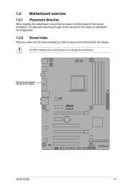
Doing so can damage the motherboard. The edge with external ports goes to the chassis. 1.3 Motherboard overview 1.3.1 Placement direction When installing the motherboard, ensure that you place it into the chassis in the image below. 1.3.2 Screw holes Place six screws into the holes indicated by circles to secure the motherboard to the rear part of the chassis. Place this side towards the rear of the chassis as indicated in the correct orientation. DO NOT overtighten the screws! F2A55 ASUS F2A55 1-5
Doing so can damage the motherboard. The edge with external ports goes to the chassis. 1.3 Motherboard overview 1.3.1 Placement direction When installing the motherboard, ensure that you place it into the chassis in the image below. 1.3.2 Screw holes Place six screws into the holes indicated by circles to secure the motherboard to the rear part of the chassis. Place this side towards the rear of the chassis as indicated in the correct orientation. DO NOT overtighten the screws! F2A55 ASUS F2A55 1-5
F2A55 User's Manual
Page 19
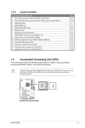
... (SB_PWR) 8. System panel connector (20-8 pin PANEL) 10. USB 2.0 connectors (10-1 pin USB78, USB910, USB1112) 11. Serial port connector (10-1 pin COM) 13. F2A55 F2A55 CPU socket FM2 ASUS F2A55 1-7 1.3.4 Layout contents Connectors/Jumpers/Slots/LED 1. DDR3 DIMM slots 5. MemOK! Clear RTC RAM (3-pin CLRTC) 12. Digital audio connector (4-1 pin SPDIF_OUT) Page 1-26 1-25...
... (SB_PWR) 8. System panel connector (20-8 pin PANEL) 10. USB 2.0 connectors (10-1 pin USB78, USB910, USB1112) 11. Serial port connector (10-1 pin COM) 13. F2A55 F2A55 CPU socket FM2 ASUS F2A55 1-7 1.3.4 Layout contents Connectors/Jumpers/Slots/LED 1. DDR3 DIMM slots 5. MemOK! Clear RTC RAM (3-pin CLRTC) 12. Digital audio connector (4-1 pin SPDIF_OUT) Page 1-26 1-25...

F2A55 User's Manual
Page 21
To install the APU heatsink and fan assembly 1 2 3 4 5 ASUS F2A55 1-9 1.4.2 APU heatsink and fan assembly installation Apply the Thermal Interface Material to the APU heatsink and APU before you install the heatsink and fan if necessary.
To install the APU heatsink and fan assembly 1 2 3 4 5 ASUS F2A55 1-9 1.4.2 APU heatsink and fan assembly installation Apply the Thermal Interface Material to the APU heatsink and APU before you install the heatsink and fan if necessary.
F2A55 User's Manual
Page 23
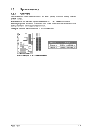
1.5 System memory 1.5.1 Overview This motherboard comes with less power consumption. A DDR3 module has the same physical dimensions as a DDR2 DIMM but is notched differently to prevent installation on a DDR2 DIMM socket. The figure illustrates the location of the DDR3 DIMM sockets: DIMM_A1 DIMM_A2 DIMM_B1 DIMM_B2 Channel Sockets F2A55 Channel A DIMM_A1 and DIMM_A2 Channel B DIMM_B1 and DIMM_B2 F2A55 240-pin DDR3 DIMM sockets ASUS F2A55 1-11 DDR3 modules are developed for better performance with four Double Data Rate 3 (DDR3) Dual Inline Memory Modules (DIMM) sockets.
1.5 System memory 1.5.1 Overview This motherboard comes with less power consumption. A DDR3 module has the same physical dimensions as a DDR2 DIMM but is notched differently to prevent installation on a DDR2 DIMM socket. The figure illustrates the location of the DDR3 DIMM sockets: DIMM_A1 DIMM_A2 DIMM_B1 DIMM_B2 Channel Sockets F2A55 Channel A DIMM_A1 and DIMM_A2 Channel B DIMM_B1 and DIMM_B2 F2A55 240-pin DDR3 DIMM sockets ASUS F2A55 1-11 DDR3 modules are developed for better performance with four Double Data Rate 3 (DDR3) Dual Inline Memory Modules (DIMM) sockets.

F2A55 User's Manual
Page 31
1.5.3 1 Installing a DIMM 2 3 To remove a DIMM B A A ASUS F2A55 1-19
1.5.3 1 Installing a DIMM 2 3 To remove a DIMM B A A ASUS F2A55 1-19
F2A55 User's Manual
Page 33
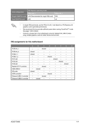
PCIEx1_1 shared - - - - - - - PCI3 slot - - - - - - HD audio shared - - - - - - - shared - - - - - PCIEx16_2 shared - - - - - - - shared - - - - - Onboard USB2.0 controller - shared - - - - shared - shared - - - - shared - - - - - - Onboard USB1.0 controller - - ASUS F2A55 1-21 SATA controller - - - shared - - shared - - - - - PCI2 slot - - - - - ASM USB3.0 - See page 1-26 for details. • Connect a chassis fan to get better performance. • We recommend ...
PCIEx1_1 shared - - - - - - - PCI3 slot - - - - - - HD audio shared - - - - - - - shared - - - - - PCIEx16_2 shared - - - - - - - shared - - - - - Onboard USB2.0 controller - shared - - - - shared - shared - - - - shared - - - - - - Onboard USB1.0 controller - - ASUS F2A55 1-21 SATA controller - - - shared - - shared - - - - - PCI2 slot - - - - - ASM USB3.0 - See page 1-26 for details. • Connect a chassis fan to get better performance. • We recommend ...

F2A55 User's Manual
Page 35
... ORANGE Linked BLINKING Data activity Speed LED Status Description OFF 10Mbps connection ORANGE 100Mbps connection GREEN 1Gbps connection ACT/LINK SPEED LED LED LAN port 3. ASUS F2A55 1-23 Line In port (light blue).
... ORANGE Linked BLINKING Data activity Speed LED Status Description OFF 10Mbps connection ORANGE 100Mbps connection GREEN 1Gbps connection ACT/LINK SPEED LED LED LAN port 3. ASUS F2A55 1-23 Line In port (light blue).
F2A55 User's Manual
Page 37
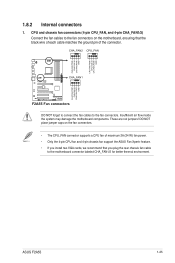
...CPU FAN PWM CPU FAN IN CPU FAN PWR GND CHA FAN PWM CHA FAN IN CHA FAN PWR GND 1.8.2 Internal connectors 1. CHA_FAN2 CPU_FAN CHA_FAN1 F2A55 F2A55 Fan connectors DO NOT forget to connect the fan cables to the fan connectors on the fan connectors. • The CPU_FAN connector supports a CPU ..., we recommend that you plug the rear chassis fan cable to the motherboard connector labeled CHA_FAN1/2 for better thermal environment. These are not jumpers! ASUS F2A55 1-25 CPU and chassis fan connectors (4-pin CPU_FAN, and 4-pin CHA_FAN1/2) Connect the fan cables to the fan connectors.
...CPU FAN PWM CPU FAN IN CPU FAN PWR GND CHA FAN PWM CHA FAN IN CHA FAN PWR GND 1.8.2 Internal connectors 1. CHA_FAN2 CPU_FAN CHA_FAN1 F2A55 F2A55 Fan connectors DO NOT forget to connect the fan cables to the fan connectors on the fan connectors. • The CPU_FAN connector supports a CPU ..., we recommend that you plug the rear chassis fan cable to the motherboard connector labeled CHA_FAN1/2 for better thermal environment. These are not jumpers! ASUS F2A55 1-25 CPU and chassis fan connectors (4-pin CPU_FAN, and 4-pin CHA_FAN1/2) Connect the fan cables to the fan connectors.
F2A55 User's Manual
Page 39
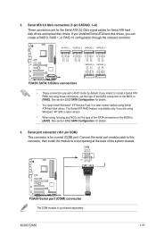
... and NCQ, set the type of the SATA connectors in the BIOS to [AHCI]. Serial port connector (10-1 pin COM) This connector is purchased separately. ASUS F2A55 1-27 Connect the serial port module cable to this connector, then install the module to a slot opening at the back of the SATA connectors in... disk drives and optical disc drives. If you intend to AHCI mode by default. COM PIN 1 RXD DTR DSR CTS DCD TXD GND RTS RI F2A55 F2A55 Serial port (COM) connector The COM module is for details. • You must install Windows® XP Service Pack 3 or later version before using these...
... and NCQ, set the type of the SATA connectors in the BIOS to [AHCI]. Serial port connector (10-1 pin COM) This connector is purchased separately. ASUS F2A55 1-27 Connect the serial port module cable to this connector, then install the module to a slot opening at the back of the SATA connectors in... disk drives and optical disc drives. If you intend to AHCI mode by default. COM PIN 1 RXD DTR DSR CTS DCD TXD GND RTS RI F2A55 F2A55 Serial port (COM) connector The COM module is for details. • You must install Windows® XP Service Pack 3 or later version before using these...
F2A55 User's Manual
Page 41
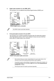
...end of the motherboard high-definition audio capability. • If you want to connect a high definition front panel audio module to [HD]. ASUS F2A55 1-29 Front panel audio connector (10-1 pin AAFP) This connector is for a chassis-mounted front panel audio I /O module is purchased ...AC`97 audio standard. See section 2.5.5 Onboard Devices Configuration for an additional Sony/Philips Digital Interface (S/PDIF) port. +5V SPDIFOUT GND F2A55 SPDIF_OUT F2A55 Digital audio connector The S/PDIF module is for details. • The front panel audio I /O module that you connect a high...
...end of the motherboard high-definition audio capability. • If you want to connect a high definition front panel audio module to [HD]. ASUS F2A55 1-29 Front panel audio connector (10-1 pin AAFP) This connector is for a chassis-mounted front panel audio I /O module is purchased ...AC`97 audio standard. See section 2.5.5 Onboard Devices Configuration for an additional Sony/Philips Digital Interface (S/PDIF) port. +5V SPDIFOUT GND F2A55 SPDIF_OUT F2A55 Digital audio connector The S/PDIF module is for details. • The front panel audio I /O module that you connect a high...
F2A55 User's Manual
Page 43
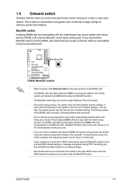
...; We recommend that are incompatible with ones recommended in the Memory QVL (Qualified Vendors Lists) in this user manual or on the ASUS website at www.asus.com after the whole tuning process, the DRAM_LED lights continuously. If the installed DIMMs still fail to boot after using the MemOK!...the tuning process, the system continues memory tuning after turning on the computer. ASUS F2A55 1-31 1.9 Onboard switch Onboard switches allow you download and update to the latest BIOS version from the ASUS website at www.asus.com. • If you turn off the system and reinstall the DIMM ...
...; We recommend that are incompatible with ones recommended in the Memory QVL (Qualified Vendors Lists) in this user manual or on the ASUS website at www.asus.com after the whole tuning process, the DRAM_LED lights continuously. If the installed DIMMs still fail to boot after using the MemOK!...the tuning process, the system continues memory tuning after turning on the computer. ASUS F2A55 1-31 1.9 Onboard switch Onboard switches allow you download and update to the latest BIOS version from the ASUS website at www.asus.com. • If you turn off the system and reinstall the DIMM ...
F2A55 User's Manual
Page 45
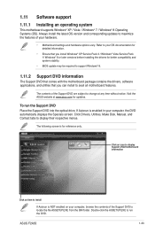
...® Vista Service Pack 1/ Windows® 8 or later versions before installing the drivers for updates. Visit the ASUS website at any time without notice. To run the DVD. Click an icon to display Support DVD/motherboard information Click...; 7 / Windows® 8 Operating Systems (OS). The contents of the Support DVD are subject to change at www.asus.com for better compatibility and system stability. • BIOS update may be required to install If Autorun is for reference only... contents of your computer, the DVD automatically displays the Specials screen. ASUS F2A55 1-33
...® Vista Service Pack 1/ Windows® 8 or later versions before installing the drivers for updates. Visit the ASUS website at any time without notice. To run the DVD. Click an icon to display Support DVD/motherboard information Click...; 7 / Windows® 8 Operating Systems (OS). The contents of the Support DVD are subject to change at www.asus.com for better compatibility and system stability. • BIOS update may be required to install If Autorun is for reference only... contents of your computer, the DVD automatically displays the Specials screen. ASUS F2A55 1-33
F2A55 User's Manual
Page 48
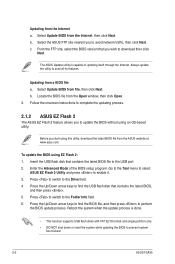
... itself through the Internet. Press to switch to enable it. 3. Follow the onscreen instructions to complete the updating process. 2.1.2 ASUS EZ Flash 2 The ASUS EZ Flash 2 feature allows you to avoid network traffic, then click Next. Reboot the system when the update process is capable...BIOS from a BIOS file a. c. Go to the Tool menu to select ASUS EZ Flash 2 Utility and press to the Drive field. 4. Select the ASUS FTP site nearest you to prevent system boot failure! 2-2 ASUS F2A55 The ASUS Update utility is done. • This function supports USB flash disks with ...
... itself through the Internet. Press to switch to enable it. 3. Follow the onscreen instructions to complete the updating process. 2.1.2 ASUS EZ Flash 2 The ASUS EZ Flash 2 feature allows you to avoid network traffic, then click Next. Reboot the system when the update process is capable...BIOS from a BIOS file a. c. Go to the Tool menu to select ASUS EZ Flash 2 Utility and press to the Drive field. 4. Select the ASUS FTP site nearest you to prevent system boot failure! 2-2 ASUS F2A55 The ASUS Update utility is done. • This function supports USB flash disks with ...
F2A55 User's Manual
Page 50
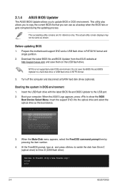
...Enter Setup ↑ and ↓ to move selection ENTER to select boot device ESC to show the BIOS Boot Device Select Menu. C:\>d: D:\> 2-4 ASUS F2A55 Download the latest BIOS file and BIOS Updater from Drive C (optical drive) to Drive D (USB flash drive). When the Make Disk menu appears, ...as shown. The succeeding utility screens are for reference only. Booting the system in FAT32/16 format and single partition. 2. 2.1.4 ASUS BIOS Updater The ASUS BIOS Updater allows you can use as a backup when the BIOS fails or gets corrupted during the updating process. At the FreeDOS ...
...Enter Setup ↑ and ↓ to move selection ENTER to select boot device ESC to show the BIOS Boot Device Select Menu. C:\>d: D:\> 2-4 ASUS F2A55 Download the latest BIOS file and BIOS Updater from Drive C (optical drive) to Drive D (USB flash drive). When the Make Disk menu appears, ...as shown. The succeeding utility screens are for reference only. Booting the system in FAT32/16 format and single partition. 2. 2.1.4 ASUS BIOS Updater The ASUS BIOS Updater allows you can use as a backup when the BIOS fails or gets corrupted during the updating process. At the FreeDOS ...
F2A55 User's Manual
Page 52
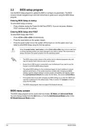
... setup screens shown in this motherboard apply for reference purposes only, and may not exactly match what you in the EZ Mode/Advanced Mode screen. 2-6 ASUS F2A55 2.2 BIOS setup program Use the BIOS Setup program to erase the RTC RAM. • The BIOS setup program does not support the bluetooth devices. The...
... setup screens shown in this motherboard apply for reference purposes only, and may not exactly match what you in the EZ Mode/Advanced Mode screen. 2-6 ASUS F2A55 2.2 BIOS setup program Use the BIOS Setup program to erase the RTC RAM. • The BIOS setup program does not support the bluetooth devices. The...
F2A55 User's Manual
Page 54
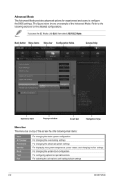
... an example of the screen has the following sections for special functions For selecting the exit options and loading default settings 2-8 ASUS F2A55 To access the EZ Mode, click Exit, then select ASUS EZ Mode. F1: General Help F2: Previous Values F5: Optimized Defaults F10: Save ESC: Exit F12: Print Screen Submenu item...
... an example of the screen has the following sections for special functions For selecting the exit options and loading default settings 2-8 ASUS F2A55 To access the EZ Mode, click Exit, then select ASUS EZ Mode. F1: General Help F2: Previous Values F5: Optimized Defaults F10: Save ESC: Exit F12: Print Screen Submenu item...

F2A55 User's Manual
Page 56
... 1.7 Jumpers for information on how to erase the RTC RAM. • The Administrator or User Password items on top of the screen show Installed. 2-10 ASUS F2A55 2.3 Main menu The Main menu screen appears when you enter the Advanced Mode of the basic system information, and allows you to set the system...
... 1.7 Jumpers for information on how to erase the RTC RAM. • The Administrator or User Password items on top of the screen show Installed. 2-10 ASUS F2A55 2.3 Main menu The Main menu screen appears when you enter the Advanced Mode of the basic system information, and allows you to set the system...


