User Guide
Page 10
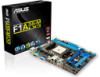
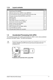
... R2.0 PCIEX16 PCIEX1_1 Lithium Cell CMOS Power AAFP PCI1 USBPW5-8 CLRTC USB78 SB_PWR USB56 64Mb BIOS AMD® A55 SATA3G_2 SPEAKER F_PANEL SATA3G_1 ASUS F1A55-M LX3 R2.0 Series motherboard User Manual 2 x Serial ATA 3.0 Gb/s cables 1 x I/O Shield User Guide Support DVD • If any of the above items is damaged or missing, ...
... R2.0 PCIEX16 PCIEX1_1 Lithium Cell CMOS Power AAFP PCI1 USBPW5-8 CLRTC USB78 SB_PWR USB56 64Mb BIOS AMD® A55 SATA3G_2 SPEAKER F_PANEL SATA3G_1 ASUS F1A55-M LX3 R2.0 Series motherboard User Manual 2 x Serial ATA 3.0 Gb/s cables 1 x I/O Shield User Guide Support DVD • If any of the above items is damaged or missing, ...
User Guide
Page 11
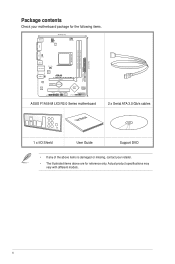
...Maximizing System Potential ASUS brings the exclusive Hybrid DIGI+ VRM design to great value motherboards to better serve a wider range of adjustable power options to 5GT/s interface and PCI Express 2.0 x 16 (at x4 speed) graphics. 100% All High-quality Conductive Polymer Capacitors (F1A55-M LX3 PLUS R2.0 only...This motherboard uses all with AMD® Radeon™ HD 6000 series graphics This motherboard supports AMD® A- & E2- ASUS F1A55-M LX3 R2.0 Series 1-1 series accelerated processor with the AMD A55 chipset allows APU voltage and VRM frequency adjustments via smart preset modes ...
...Maximizing System Potential ASUS brings the exclusive Hybrid DIGI+ VRM design to great value motherboards to better serve a wider range of adjustable power options to 5GT/s interface and PCI Express 2.0 x 16 (at x4 speed) graphics. 100% All High-quality Conductive Polymer Capacitors (F1A55-M LX3 PLUS R2.0 only...This motherboard uses all with AMD® Radeon™ HD 6000 series graphics This motherboard supports AMD® A- & E2- ASUS F1A55-M LX3 R2.0 Series 1-1 series accelerated processor with the AMD A55 chipset allows APU voltage and VRM frequency adjustments via smart preset modes ...

User Guide
Page 13
... the RTC data. Simply shut down and reboot the system, and the BIOS automatically restores the CPU parameters to overclocking failure. ASUS F1A55-M LX3 R2.0 Series 1-3 C.P.R. This is European Union´s Energy-related Products (ErP) ready, and ErP requires products to meet ...certain energy efficiency requirements in line with ASUS vision of creating environment-friendly and energyefficient products through product design and innovation to reduce carbon footprint of the product and thus ...
... the RTC data. Simply shut down and reboot the system, and the BIOS automatically restores the CPU parameters to overclocking failure. ASUS F1A55-M LX3 R2.0 Series 1-3 C.P.R. This is European Union´s Energy-related Products (ErP) ready, and ErP requires products to meet ...certain energy efficiency requirements in line with ASUS vision of creating environment-friendly and energyefficient products through product design and innovation to reduce carbon footprint of the product and thus ...
User Guide
Page 15
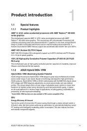
Doing so can damage the motherboard. 1.3 Motherboard overview 1.3.1 Placement direction When installing the motherboard, ensure that you place it into the holes indicated by circles to secure the motherboard to the rear part of the chassis. Place this side towards the rear of the chassis as indicated in the image below. 1.3.2 Screw holes Place six screws into the chassis in the correct orientation. DO NOT overtighten the screws! F1A55-M LX3 PLUS R2.0 ASUS F1A55-M LX3 R2.0 Series 1-5 The edge with external ports goes to the chassis.
Doing so can damage the motherboard. 1.3 Motherboard overview 1.3.1 Placement direction When installing the motherboard, ensure that you place it into the holes indicated by circles to secure the motherboard to the rear part of the chassis. Place this side towards the rear of the chassis as indicated in the image below. 1.3.2 Screw holes Place six screws into the chassis in the correct orientation. DO NOT overtighten the screws! F1A55-M LX3 PLUS R2.0 ASUS F1A55-M LX3 R2.0 Series 1-5 The edge with external ports goes to the chassis.
User Guide
Page 17
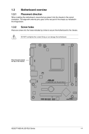
... comes with AMD® Radeon™ HD 6000 series graphics. series accelerated processors with an FM1 socket designed for the FM1 socket. F1A55-M LX3 PLUS R2.0 F1A55-M LX3 PLUS R2.0 CPU socket FM1 ASUS F1A55-M LX3 R2.0 Series 1-7 System panel connector (10-1 pin F_PANEL) 9. The APU fits in only one correct orientation. Ensure that you use a APU...
... comes with AMD® Radeon™ HD 6000 series graphics. series accelerated processors with an FM1 socket designed for the FM1 socket. F1A55-M LX3 PLUS R2.0 F1A55-M LX3 PLUS R2.0 CPU socket FM1 ASUS F1A55-M LX3 R2.0 Series 1-7 System panel connector (10-1 pin F_PANEL) 9. The APU fits in only one correct orientation. Ensure that you use a APU...
User Guide
Page 19
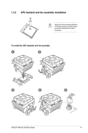
To install the APU heatsink and fan assembly 1 2 3 4 5 ASUS F1A55-M LX3 R2.0 Series 1-9 1.4.2 APU heatsink and fan assembly installation Apply the Thermal Interface Material to the APU heatsink and APU before you install the heatsink and fan if necessary.
To install the APU heatsink and fan assembly 1 2 3 4 5 ASUS F1A55-M LX3 R2.0 Series 1-9 1.4.2 APU heatsink and fan assembly installation Apply the Thermal Interface Material to the APU heatsink and APU before you install the heatsink and fan if necessary.
User Guide
Page 21
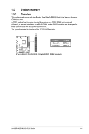
The figure illustrates the location of the DDR3 DIMM sockets: DIMM_A1 DIMM_B1 F1A55-M LX3 PLUS R2.0 Channel Channel A Channel B Sockets DIMM_A1 DIMM_B1 F1A55-M LX3 PLUS R2.0 240-pin DDR3 DIMM sockets ASUS F1A55-M LX3 R2.0 Series 1-11 A DDR3 module has the same physical dimensions as a DDR2 DIMM but is notched differently to prevent installation on a DDR2 DIMM socket. 1.5 System memory 1.5.1 Overview This motherboard comes with less power consumption. DDR3 modules are developed for better performance with two Double Data Rate 3 (DDR3) Dual Inline Memory Modules (DIMM) sockets.
The figure illustrates the location of the DDR3 DIMM sockets: DIMM_A1 DIMM_B1 F1A55-M LX3 PLUS R2.0 Channel Channel A Channel B Sockets DIMM_A1 DIMM_B1 F1A55-M LX3 PLUS R2.0 240-pin DDR3 DIMM sockets ASUS F1A55-M LX3 R2.0 Series 1-11 A DDR3 module has the same physical dimensions as a DDR2 DIMM but is notched differently to prevent installation on a DDR2 DIMM socket. 1.5 System memory 1.5.1 Overview This motherboard comes with less power consumption. DDR3 modules are developed for better performance with two Double Data Rate 3 (DDR3) Dual Inline Memory Modules (DIMM) sockets.

User Guide
Page 25
...; • 1.65V • • XMP 1.35V • • 1.65V • • 1.65V 1.65V 1.65V 1.65V - • • • • • • • • • • ASUS F1A55-M LX3 R2.0 Series 1-15 Size SS/ DS Chip Brand Chip No. Timing A-Data AX3U1600XB2G79-2X(XMP) 4GB(2 x 2GB) DS - - 7-9-7-21 A-Data AX3U1600GC4G9-2G(XMP) 8GB(2 x 4GB...
...; • 1.65V • • XMP 1.35V • • 1.65V • • 1.65V 1.65V 1.65V 1.65V - • • • • • • • • • • ASUS F1A55-M LX3 R2.0 Series 1-15 Size SS/ DS Chip Brand Chip No. Timing A-Data AX3U1600XB2G79-2X(XMP) 4GB(2 x 2GB) DS - - 7-9-7-21 A-Data AX3U1600GC4G9-2G(XMP) 8GB(2 x 4GB...

User Guide
Page 27
1.5.3 1 Installing a DIMM 2 3 To remove a DIMM B A ASUS F1A55-M LX3 R2.0 Series 1-17
1.5.3 1 Installing a DIMM 2 3 To remove a DIMM B A ASUS F1A55-M LX3 R2.0 Series 1-17
User Guide
Page 29
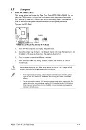
... need to clear the RTC when the system hangs due to default values. To erase the RTC RAM: F1A55-M LX3 PLUS R2.0 CLRTC 12 23 Normal (Default) Clear RTC F1A55-M LX3 PLUS R2.0 Clear RTC RAM 1. ASUS F1A55-M LX3 R2.0 Series 1-19 Hold down and reboot the system so the BIOS can clear the CMOS memory of...
... need to clear the RTC when the system hangs due to default values. To erase the RTC RAM: F1A55-M LX3 PLUS R2.0 CLRTC 12 23 Normal (Default) Clear RTC F1A55-M LX3 PLUS R2.0 Clear RTC RAM 1. ASUS F1A55-M LX3 R2.0 Series 1-19 Hold down and reboot the system so the BIOS can clear the CMOS memory of...

User Guide
Page 31
... port connects to a Local Area Network (LAN) through a network hub. Microphone port (pink). Refer to support an 8-channel audio output. Line In port (light blue). ASUS F1A55-M LX3 R2.0 Series 1-21 In 4-channel, 6-channel, and 8-channel configurations, the function of the audio ports in the front panel to the audio configuration table below...
... port connects to a Local Area Network (LAN) through a network hub. Microphone port (pink). Refer to support an 8-channel audio output. Line In port (light blue). ASUS F1A55-M LX3 R2.0 Series 1-21 In 4-channel, 6-channel, and 8-channel configurations, the function of the audio ports in the front panel to the audio configuration table below...
User Guide
Page 33
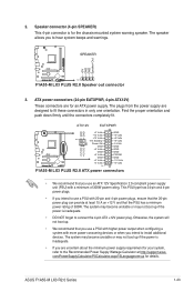
...GND GND +12V DC +12V DC +5 Volts GND GND GND +5 Volts PSON# GND GND +3 Volts -12 Volts +3 Volts +3 Volts PIN 1 F1A55-M LX3 PLUS R2.0 ATX power connectors • We recommend that you use a PSU with higher power output when configuring a system with more power-consuming devices or...plugs, ensure that the 20-pin power plug can provide at http://support.asus. Otherwise, the system will not boot up. • We recommend that you intend to install additional devices. ASUS F1A55-M LX3 R2.0 Series 1-23 com/PowerSupplyCalculator/PSCalculator.aspx?SLanguage=en-us for an ATX...
...GND GND +12V DC +12V DC +5 Volts GND GND GND +5 Volts PSON# GND GND +3 Volts -12 Volts +3 Volts +3 Volts PIN 1 F1A55-M LX3 PLUS R2.0 ATX power connectors • We recommend that you use a PSU with higher power output when configuring a system with more power-consuming devices or...plugs, ensure that the 20-pin power plug can provide at http://support.asus. Otherwise, the system will not boot up. • We recommend that you intend to install additional devices. ASUS F1A55-M LX3 R2.0 Series 1-23 com/PowerSupplyCalculator/PSCalculator.aspx?SLanguage=en-us for an ATX...
User Guide
Page 35
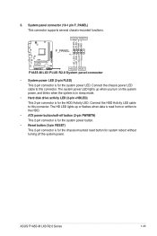
... R2.0 F_PANEL PIN 1 HD_LED+ HD_LED- Connect the chassis power LED cable to this connector. Connect the HDD Activity LED cable to this connector. ASUS F1A55-M LX3 R2.0 Series 1-25 The HD LED lights up when you turn on the system power, and blinks when the system is in sleep mode. • ...Hard disk drive activity LED (2-pin +HDLED) This 2-pin connector is for the HDD Activity LED. Ground Reset +HDLED RESET F1A55-M LX3 PLUS R2.0 System panel connector • System power LED (2-pin PLED) This 2-pin connector is for the system power LED.
... R2.0 F_PANEL PIN 1 HD_LED+ HD_LED- Connect the chassis power LED cable to this connector. Connect the HDD Activity LED cable to this connector. ASUS F1A55-M LX3 R2.0 Series 1-25 The HD LED lights up when you turn on the system power, and blinks when the system is in sleep mode. • ...Hard disk drive activity LED (2-pin +HDLED) This 2-pin connector is for the HDD Activity LED. Ground Reset +HDLED RESET F1A55-M LX3 PLUS R2.0 System panel connector • System power LED (2-pin PLED) This 2-pin connector is for the system power LED.
User Guide
Page 37
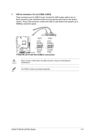
... specification that supports up to a slot opening at the back of the system chassis. The USB 2.0 module is purchased separately. ASUS F1A55-M LX3 R2.0 Series 1-27 Connect the USB module cable to any of these connectors, then install the module to 480Mbps connection speed. Doing... so will damage the motherboard! USB78 USB56 USB+5V USB_P6USB_P6+ GND NC USB+5V USB_P8USB_P8+ GND NC F1A55-M LX3 PLUS R2.0 PIN 1 PIN 1 USB+5V USB_P5USB_P5+ GND USB+5V USB_P7USB_P7+ GND F1A55-M LX3 PLUS R2.0 USB2.0 connectors Never connect a 1394 cable to the USB connectors. 7. USB 2.0 connectors ...
... specification that supports up to a slot opening at the back of the system chassis. The USB 2.0 module is purchased separately. ASUS F1A55-M LX3 R2.0 Series 1-27 Connect the USB module cable to any of these connectors, then install the module to 480Mbps connection speed. Doing... so will damage the motherboard! USB78 USB56 USB+5V USB_P6USB_P6+ GND NC USB+5V USB_P8USB_P8+ GND NC F1A55-M LX3 PLUS R2.0 PIN 1 PIN 1 USB+5V USB_P5USB_P5+ GND USB+5V USB_P7USB_P7+ GND F1A55-M LX3 PLUS R2.0 USB2.0 connectors Never connect a 1394 cable to the USB connectors. 7. USB 2.0 connectors ...
User Guide
Page 40
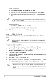
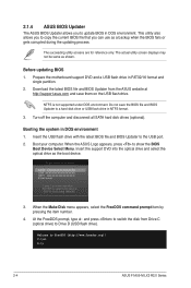
...the Open window, then click Open. 3. Locate the BIOS file from a BIOS file a. Follow the onscreen instructions to complete the updating process. 2.1.2 ASUS EZ Flash 2 The ASUS EZ Flash 2 feature allows you to the USB port. 2. Insert the USB flash disk that you start using EZ Flash 2: 1. Press to ... process. Enter the Advanced Mode of updating itself through the Internet. Select Update BIOS from the Internet a. b. c. Select Update BIOS from the ASUS website at www.asus.com. Before you wish to prevent system boot failure! 2-2 ASUS F1A55-M LX3 R2.0 Series
...the Open window, then click Open. 3. Locate the BIOS file from a BIOS file a. Follow the onscreen instructions to complete the updating process. 2.1.2 ASUS EZ Flash 2 The ASUS EZ Flash 2 feature allows you to the USB port. 2. Insert the USB flash disk that you start using EZ Flash 2: 1. Press to ... process. Enter the Advanced Mode of updating itself through the Internet. Select Update BIOS from the Internet a. b. c. Select Update BIOS from the ASUS website at www.asus.com. Before you wish to prevent system boot failure! 2-2 ASUS F1A55-M LX3 R2.0 Series
User Guide
Page 42
... the motherboard support DVD and a USB flash drive in DOS environment 1. Booting the system in FAT32/16 format and single partition. 2. When the ASUS Logo appears, press to the USB port. 2. Insert the support DVD into the optical drive and select the optical drive as a backup when the... with the latest BIOS file and BIOS Updater to show the BIOS Boot Device Select Menu. Welcome to boot using defaults 3. C:\>d: D:\> 2-4 ASUS F1A55-M LX3 R2.0 Series Do not save them on the USB flash drive. Turn off the computer and disconnect all SATA hard disk drives (optional...
... the motherboard support DVD and a USB flash drive in DOS environment 1. Booting the system in FAT32/16 format and single partition. 2. When the ASUS Logo appears, press to the USB port. 2. Insert the support DVD into the optical drive and select the optical drive as a backup when the... with the latest BIOS file and BIOS Updater to show the BIOS Boot Device Select Menu. Welcome to boot using defaults 3. C:\>d: D:\> 2-4 ASUS F1A55-M LX3 R2.0 Series Do not save them on the USB flash drive. Turn off the computer and disconnect all SATA hard disk drives (optional...
User Guide
Page 44
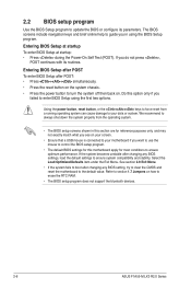
... to turn the system off then back on how to erase the RTC RAM. • The BIOS setup program does not support the bluetooth devices. 2-6 ASUS F1A55-M LX3 R2.0 Series Do this option only if you do not press , POST continues with its parameters. See section 2.9 Exit Menu. • If the system fails...
... to turn the system off then back on how to erase the RTC RAM. • The BIOS setup program does not support the bluetooth devices. 2-6 ASUS F1A55-M LX3 R2.0 Series Do this option only if you do not press , POST continues with its parameters. See section 2.9 Exit Menu. • If the system fails...
User Guide
Page 46
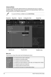
Refer to configure the BIOS settings. To access the EZ Mode, click Exit, then select ASUS EZ Mode. Back button Menu items Menu bar Configuration fields General help Submenu item Pop-up window Navigation keys Menu bar The menu bar on .... The figure below shows an example of the screen has the following sections for special functions For selecting the exit options and loading default settings 2-8 ASUS F1A55-M LX3 R2.0 Series
Refer to configure the BIOS settings. To access the EZ Mode, click Exit, then select ASUS EZ Mode. Back button Menu items Menu bar Configuration fields General help Submenu item Pop-up window Navigation keys Menu bar The menu bar on .... The figure below shows an example of the screen has the following sections for special functions For selecting the exit options and loading default settings 2-8 ASUS F1A55-M LX3 R2.0 Series

User Guide
Page 48
... Administrator or User Password items on how to clear the BIOS password. See section 1.7 Jumpers for information on top of the screen show Installed. 2-10 ASUS F1A55-M LX3 R2.0 Series Advanced Mode Exit Main Ai Tweaker Advanced Monitor BIOS Information BIOS Version Build Date 0401 x64 05/02/2012 CPU Information AMD A8...
... Administrator or User Password items on how to clear the BIOS password. See section 1.7 Jumpers for information on top of the screen show Installed. 2-10 ASUS F1A55-M LX3 R2.0 Series Advanced Mode Exit Main Ai Tweaker Advanced Monitor BIOS Information BIOS Version Build Date 0401 x64 05/02/2012 CPU Information AMD A8...

User Guide
Page 50
2.4 Ai Tweaker menu The Ai Tweaker menu items allow you installed on the motherboard. The configuration options for this section vary depending on the CPU and DIMM model you to configure overclocking-related items. Be cautious when changing the settings of the Ai Tweaker menu items. Incorrect field values can cause the system to display the following items: Target CPU Speed : xxxxMHz Displays the current CPU speed. Scroll down to malfunction. Target DRAM Speed : xxxxMHz Displays the current DRAM speed. 2-12 ASUS F1A55-M LX3 R2.0 Series
2.4 Ai Tweaker menu The Ai Tweaker menu items allow you installed on the motherboard. The configuration options for this section vary depending on the CPU and DIMM model you to configure overclocking-related items. Be cautious when changing the settings of the Ai Tweaker menu items. Incorrect field values can cause the system to display the following items: Target CPU Speed : xxxxMHz Displays the current CPU speed. Scroll down to malfunction. Target DRAM Speed : xxxxMHz Displays the current DRAM speed. 2-12 ASUS F1A55-M LX3 R2.0 Series


