User Manual
Page 2
... obtaining the full corresponding source code we would be distributed WITHOUT ANY WARRANTY and licensed under various Free Open Source Software licenses. SPECIFICATIONS AND INFORMATION CONTAINED IN THIS MANUAL ARE FURNISHED FOR INFORMATIONAL USE ONLY, AND ARE SUBJECT TO CHANGE AT ANY TIME WITHOUT NOTICE, AND SHOULD NOT BE CONSTRUED AS A COMMITMENT BY ASUS. Products and corporate names...
... obtaining the full corresponding source code we would be distributed WITHOUT ANY WARRANTY and licensed under various Free Open Source Software licenses. SPECIFICATIONS AND INFORMATION CONTAINED IN THIS MANUAL ARE FURNISHED FOR INFORMATIONAL USE ONLY, AND ARE SUBJECT TO CHANGE AT ANY TIME WITHOUT NOTICE, AND SHOULD NOT BE CONSTRUED AS A COMMITMENT BY ASUS. Products and corporate names...
User Manual
Page 4
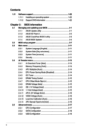
... 2.1.1 ASUS Update utility 2-1 2.1.2 ASUS EZ Flash 2 2-2 2.1.3 ASUS CrashFree BIOS 3 utility 2-3 2.1.4 ASUS BIOS Updater 2-4 2.2 BIOS setup program 2-7 2.3 Main menu 2-11 2.3.1 System Language [English 2-11 2.3.2 System Date [Day xx/xx/xxxx 2-11 2.3.3 System Time [xx:xx:xx 2-11 2.3.4 Security 2-11 2.4 Ai Tweaker menu 2-13 2.4.1 Ai Overclock Tuner [Auto 2-14 2.4.2 Memory Frequency [Auto 2-14 2.4.3 APU Multiplier [Auto 2-14 2.4.4 EPU Power Saving Mode [Disabled 2-14 2.4.5 OC Tuner 2-14 2.4.6 DRAM Timing Control 2-15 2.4.7 CPU Offset Mode Sign 2-15 2.4.8 DRAM Voltage [Auto 2-15...
... 2.1.1 ASUS Update utility 2-1 2.1.2 ASUS EZ Flash 2 2-2 2.1.3 ASUS CrashFree BIOS 3 utility 2-3 2.1.4 ASUS BIOS Updater 2-4 2.2 BIOS setup program 2-7 2.3 Main menu 2-11 2.3.1 System Language [English 2-11 2.3.2 System Date [Day xx/xx/xxxx 2-11 2.3.3 System Time [xx:xx:xx 2-11 2.3.4 Security 2-11 2.4 Ai Tweaker menu 2-13 2.4.1 Ai Overclock Tuner [Auto 2-14 2.4.2 Memory Frequency [Auto 2-14 2.4.3 APU Multiplier [Auto 2-14 2.4.4 EPU Power Saving Mode [Disabled 2-14 2.4.5 OC Tuner 2-14 2.4.6 DRAM Timing Control 2-15 2.4.7 CPU Offset Mode Sign 2-15 2.4.8 DRAM Voltage [Auto 2-15...
User Manual
Page 14
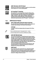
... EZ Mode displays frequently-accessed setup info, while the Advanced Mode is an Unified Extensible Firmware Interface that offers a user-friendly interface that goes beyond traditional keyboardonly BIOS controls to overclock without exiting or rebooting the OS; This easy OC tool allows you to enable more intricate system settings. CrossFireX™ allows higher antialiasing, anisotropic filtering, shading, and texture settings. Adjust your USB device's conditions. AMD...
... EZ Mode displays frequently-accessed setup info, while the Advanced Mode is an Unified Extensible Firmware Interface that offers a user-friendly interface that goes beyond traditional keyboardonly BIOS controls to overclock without exiting or rebooting the OS; This easy OC tool allows you to enable more intricate system settings. CrossFireX™ allows higher antialiasing, anisotropic filtering, shading, and texture settings. Adjust your USB device's conditions. AMD...
User Manual
Page 15
... ambient temperatures caused by power surges from switching power supply unit (PSU). This all the exclusive ASUS features into 256-color boot logos to supervise overclocking, energy management, fan speed control, and voltage and sensor readings. The built-in different geographic regions and your favorite photos into one software offers diverse and ease to switch back and forth between different utilities. C.P.R. feature automatically restores the CPU default settings...
... ambient temperatures caused by power surges from switching power supply unit (PSU). This all the exclusive ASUS features into 256-color boot logos to supervise overclocking, energy management, fan speed control, and voltage and sensor readings. The built-in different geographic regions and your favorite photos into one software offers diverse and ease to switch back and forth between different utilities. C.P.R. feature automatically restores the CPU default settings...
User Manual
Page 23
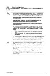
... frequency, refer to section 2.4 Ai Tweaker menu for manual memory frequency adjustment. • For system stability, use of memory, we recommend that you install the memory modules from the blue slots for overclocking may operate at www.asus.com for the dual-channel configuration. The system maps the total size of the lower-sized channel for the latest memory modules' Qualified Vendors List (QVL). Under the default state, some AMD CPU models may not support...
... frequency, refer to section 2.4 Ai Tweaker menu for manual memory frequency adjustment. • For system stability, use of memory, we recommend that you install the memory modules from the blue slots for overclocking may operate at www.asus.com for the dual-channel configuration. The system maps the total size of the lower-sized channel for the latest memory modules' Qualified Vendors List (QVL). Under the default state, some AMD CPU models may not support...
User Manual
Page 25
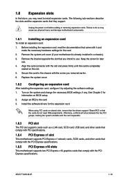
... PCI Express x16 graphics cards that came with the PCI Express specifications. Before installing the expansion card, read the documentation that comply with it by adjusting the software settings. 1. Remove the system unit cover (if your motherboard is completely seated on shared slots, ensure that the drivers support "Share IRQ" or that the cards do so may cause you may need IRQ assignments. Turn on BIOS setup. 2. Install the software drivers for later use . ASUS F1A55-M LE...
... PCI Express x16 graphics cards that came with the PCI Express specifications. Before installing the expansion card, read the documentation that comply with it by adjusting the software settings. 1. Remove the system unit cover (if your motherboard is completely seated on shared slots, ensure that the drivers support "Share IRQ" or that the cards do so may cause you may need IRQ assignments. Turn on BIOS setup. 2. Install the software drivers for later use . ASUS F1A55-M LE...
User Manual
Page 26
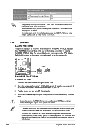
... power cord and turn ON the computer. 4. Move the jumper cap from pins 1-2 (default) to overclocking. Shut down the key during the boot process and enter BIOS setup to clear the CMOS RTC RAM data. VGA configuration Single VGA/PCIe card Dual VGA/PCIe card PCI Express operating mode PCIe x16_1 x16 (Recommended for single VGA card) x16 PCIe x16_2 N/A x4 • In single VGA card mode, use the CPU Parameter Recall (C.P.R) feature. See page 1-18 for details. • Connect a chassis fan to the motherboard connector labeled CHA_FAN when using multiple graphics cards...
... power cord and turn ON the computer. 4. Move the jumper cap from pins 1-2 (default) to overclocking. Shut down the key during the boot process and enter BIOS setup to clear the CMOS RTC RAM data. VGA configuration Single VGA/PCIe card Dual VGA/PCIe card PCI Express operating mode PCIe x16_1 x16 (Recommended for single VGA card) x16 PCIe x16_2 N/A x4 • In single VGA card mode, use the CPU Parameter Recall (C.P.R) feature. See page 1-18 for details. • Connect a chassis fan to the motherboard connector labeled CHA_FAN when using multiple graphics cards...
User Manual
Page 28
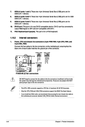
...-D compatible device. These two 4-pin Universal Serial Bus (USB) ports are not jumpers! DO NOT place jumper caps on the motherboard, ensuring that the black wire of each cable matches the ground pin of maximum 2A (24 W) fan power. • Only the CPU_FAN and CHA_FAN connectors support the ASUS Fan Xpert feature. • If you install two VGA cards, we recommend that you plug the rear chassis fan cable to the fan connectors on the fan connectors. • The CPU_FAN connector supports a CPU fan...
...-D compatible device. These two 4-pin Universal Serial Bus (USB) ports are not jumpers! DO NOT place jumper caps on the motherboard, ensuring that the black wire of each cable matches the ground pin of maximum 2A (24 W) fan power. • Only the CPU_FAN and CHA_FAN connectors support the ASUS Fan Xpert feature. • If you install two VGA cards, we recommend that you plug the rear chassis fan cable to the fan connectors on the fan connectors. • The CPU_FAN connector supports a CPU fan...
User Manual
Page 30
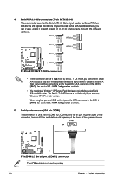
... connector, then install the module to [RAID]. See section 2.5.2 SATA Configuration for Serial ATA hard disk drives and optical disc drives. See section 2.5.2 SATA Configuration for a serial (COM) port. If you can connect Serial ATA boot/data hard disk drives to these connectors, set to [AHCI]. If you installed Serial ATA hard disk drives, you intend to create a Serial ATA RAID set the type of the SATA connectors in the BIOS to a slot opening at the back of the SATA connectors in the BIOS to IDE mode by default. In IDE mode, you are using Windows...
... connector, then install the module to [RAID]. See section 2.5.2 SATA Configuration for Serial ATA hard disk drives and optical disc drives. See section 2.5.2 SATA Configuration for a serial (COM) port. If you can connect Serial ATA boot/data hard disk drives to these connectors, set to [AHCI]. If you installed Serial ATA hard disk drives, you intend to create a Serial ATA RAID set the type of the SATA connectors in the BIOS to a slot opening at the back of the SATA connectors in the BIOS to IDE mode by default. In IDE mode, you are using Windows...

User Manual
Page 34
... NOT enabled on your hardware. • Motherboard settings and hardware options vary. The contents of the Support DVD to locate the file ASSETUP.EXE from the BIN folder. To run the DVD. 1-22 Chapter 1: Product introduction 1.11 Software support 1.11.1 Installing an operating system This motherboard supports Windows® XP / Vista / 7 Operating Systems (OS). Click an icon to display Support DVD/ motherboard information Click an item to change at www.asus...
... NOT enabled on your hardware. • Motherboard settings and hardware options vary. The contents of the Support DVD to locate the file ASSETUP.EXE from the BIN folder. To run the DVD. 1-22 Chapter 1: Product introduction 1.11 Software support 1.11.1 Installing an operating system This motherboard supports Windows® XP / Vista / 7 Operating Systems (OS). Click an icon to display Support DVD/ motherboard information Click an item to change at www.asus...
User Manual
Page 35
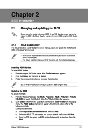
.... The Drivers menu appears. 2. Copy the original motherboard BIOS using this utility. Installing ASUS Update To install ASUS Update: 1. Quit all Windows® applications before you to manage, save, and update the motherboard BIOS in Windows® environment. • ASUS Update requires an Internet connection either of the original motherboard BIOS file to a USB flash disk in case you to avoid network traffic, then click Next. Updating the BIOS To update the BIOS: 1. Click Update button from the Quick Bar, and then click ASUS Update from...
.... The Drivers menu appears. 2. Copy the original motherboard BIOS using this utility. Installing ASUS Update To install ASUS Update: 1. Quit all Windows® applications before you to manage, save, and update the motherboard BIOS in Windows® environment. • ASUS Update requires an Internet connection either of the original motherboard BIOS file to a USB flash disk in case you to avoid network traffic, then click Next. Updating the BIOS To update the BIOS: 1. Click Update button from the Quick Bar, and then click ASUS Update from...

User Manual
Page 37
... you to enter BIOS Setup to the Folder Info field. 6. DO NOT shut down or reset the system while updating the BIOS to load default BIOS values. When found, the utility reads the BIOS file and enters ASUS EZ Flash 2 utility automatically. 4. Doing so can restore a corrupted BIOS file using the motherboard support DVD or a USB flash drive that allows you press to prevent system boot failure! 2.1.3 ASUS CrashFree BIOS 3 utility The ASUS CrashFree BIOS 3 is done. • This function supports USB flash disks with FAT...
... you to enter BIOS Setup to the Folder Info field. 6. DO NOT shut down or reset the system while updating the BIOS to load default BIOS values. When found, the utility reads the BIOS file and enters ASUS EZ Flash 2 utility automatically. 4. Doing so can restore a corrupted BIOS file using the motherboard support DVD or a USB flash drive that allows you press to prevent system boot failure! 2.1.3 ASUS CrashFree BIOS 3 utility The ASUS CrashFree BIOS 3 is done. • This function supports USB flash disks with FAT...
User Manual
Page 38
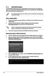
... USB port. 2. C:\>d: D:\> 2-4 ASUS F1A55-M LE Before updating BIOS 1. Download the latest BIOS file and BIOS Updater from Drive C (optical drive) to a hard disk drive or USB flash drive in NTFS format. 3. Boot your computer. When the Make Disk menu appears, select the FreeDOS command prompt item by pressing the item number. 4. Prepare the motherboard support DVD and a USB flash drive in DOS environment 1. Do not save them on the USB flash drive. Turn off the computer and disconnect all SATA hard disk drives (optional). At the FreeDOS prompt, type...
... USB port. 2. C:\>d: D:\> 2-4 ASUS F1A55-M LE Before updating BIOS 1. Download the latest BIOS file and BIOS Updater from Drive C (optical drive) to a hard disk drive or USB flash drive in NTFS format. 3. Boot your computer. When the Make Disk menu appears, select the FreeDOS command prompt item by pressing the item number. 4. Prepare the motherboard support DVD and a USB flash drive in DOS environment 1. Do not save them on the USB flash drive. Turn off the computer and disconnect all SATA hard disk drives (optional). At the FreeDOS prompt, type...

User Manual
Page 40
... press . Are you have disconnected them. 2-6 ASUS F1A55-M LE ASUSTek BIOS Updater for details. • Ensure to connect all SATA hard disk drives after updating BIOS. • Ensure to load the BIOS default settings to the DOS prompt after updating the BIOS file if you sure to select the BIOS file and press . Updating the BIOS file To update the BIOS file using BIOS Updater 1. Press to switch between screen fields and use the keys to update BIOS? At the FreeDOS prompt, type bupdater /pc /g and press .
... press . Are you have disconnected them. 2-6 ASUS F1A55-M LE ASUSTek BIOS Updater for details. • Ensure to connect all SATA hard disk drives after updating BIOS. • Ensure to load the BIOS default settings to the DOS prompt after updating the BIOS file if you sure to select the BIOS file and press . Updating the BIOS file To update the BIOS file using BIOS Updater 1. Press to switch between screen fields and use the keys to update BIOS? At the FreeDOS prompt, type bupdater /pc /g and press .
User Manual
Page 48
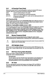
... also key in the desired value using the numeric keypad. The values range from 90.0MHz to start automatic overclocking. 2-14 ASUS F1A55-M LE Configuration options: [Auto] [Light Power Saving Mode] [Medium Power Saving Mode] [Max Power Saving Mode] 2.4.5 OC Tuner OC Tuner automatically overclocks the frequency and voltage of these preset overclocking configuration options: [Auto] Loads the optimal settings for enhancing the system performance. 2.4.1 Ai Overclock Tuner [Auto] Allows you to select the CPU overclocking options to enable or disable the EPU power saving...
... also key in the desired value using the numeric keypad. The values range from 90.0MHz to start automatic overclocking. 2-14 ASUS F1A55-M LE Configuration options: [Auto] [Light Power Saving Mode] [Medium Power Saving Mode] [Max Power Saving Mode] 2.4.5 OC Tuner OC Tuner automatically overclocks the frequency and voltage of these preset overclocking configuration options: [Auto] Loads the optimal settings for enhancing the system performance. 2.4.1 Ai Overclock Tuner [Auto] Allows you to select the CPU overclocking options to enable or disable the EPU power saving...
User Manual
Page 50
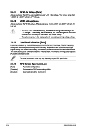
... VRM thermal. 2.4.11 APU1.2V Voltage [Auto] Allows you to set this function for EMI control. 2-16 ASUS F1A55-M LE This item allows you to set the VDDA voltage. The CPU working voltage will decrease proportionally to set the APU (Accelerated Processor Unit) 1.2V voltage. The values range from 2.5000V to 2.8000V with a 0.01V interval. 2.4.12 VDDA Voltage [Auto] Allows you to CPU loading. Configuration options: [Auto] [Disabled] [Enabled] The actual performance boost may...
... VRM thermal. 2.4.11 APU1.2V Voltage [Auto] Allows you to set this function for EMI control. 2-16 ASUS F1A55-M LE This item allows you to set the VDDA voltage. The CPU working voltage will decrease proportionally to set the APU (Accelerated Processor Unit) 1.2V voltage. The values range from 2.5000V to 2.8000V with a 0.01V interval. 2.4.12 VDDA Voltage [Auto] Allows you to CPU loading. Configuration options: [Auto] [Disabled] [Enabled] The actual performance boost may...

User Manual
Page 51
...Mode Exit Main Ai Tweaker > CPU Configuration > SATA Configuration > USB Configuration > NB Configuration > Onboard Devices Configuration > APM Advanced Monitor Boot Tool CPU Configuration Parameters →←: Select Screen ↑↓: Select Item Enter: Select +/-: Change Opt. C6 Mode [Auto] Enables or disables C6 mode. Configuration options: [Auto] [Enabled] [Disabled] CPB Mode [Auto] Disables the CPB (Core Performance Boost) mode or set it to malfunction. F1: General Help F2: Previous Values F5: Optimized Defaults F10: Save ESC: Exit F12: Print Screen Version...
...Mode Exit Main Ai Tweaker > CPU Configuration > SATA Configuration > USB Configuration > NB Configuration > Onboard Devices Configuration > APM Advanced Monitor Boot Tool CPU Configuration Parameters →←: Select Screen ↑↓: Select Item Enter: Select +/-: Change Opt. C6 Mode [Auto] Enables or disables C6 mode. Configuration options: [Auto] [Enabled] [Disabled] CPB Mode [Auto] Disables the CPB (Core Performance Boost) mode or set it to malfunction. F1: General Help F2: Previous Values F5: Optimized Defaults F10: Save ESC: Exit F12: Print Screen Version...
User Manual
Page 52
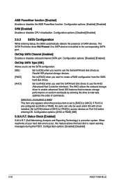
... the onboard storage driver to use the AHCI (Advanced Host Controller Interface). Set to [IDE] instead of [AHCI or RAID] to access devices on random workloads by allowing the drive to report warning messages during the POST. Configuration options: [Enabled] [Disabled] 2-18 ASUS F1A55-M LE Configuration options: [Disabled] [Enabled] 2.5.2 SATA Configuration While entering Setup, the BIOS automatically detects the presence of your hard disk errors occur, this feature allows the hard disk to internally optimize the order of commands. Status Check [Enabled] S.M.A.R.T. (Self-Monitoring...
... the onboard storage driver to use the AHCI (Advanced Host Controller Interface). Set to [IDE] instead of [AHCI or RAID] to access devices on random workloads by allowing the drive to report warning messages during the POST. Configuration options: [Enabled] [Disabled] 2-18 ASUS F1A55-M LE Configuration options: [Disabled] [Enabled] 2.5.2 SATA Configuration While entering Setup, the BIOS automatically detects the presence of your hard disk errors occur, this feature allows the hard disk to internally optimize the order of commands. Status Check [Enabled] S.M.A.R.T. (Self-Monitoring...
User Manual
Page 53
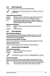
... the front panel audio connector (AAFP) mode to high definition audio. [AC97] Sets the front panel audio connector (AAFP) mode to detect the presence of Internal Graphics Device will keep memory reserved. The following two items appear only when you set the front panel audio connector (AAFP) mode to legacy AC'97 or highdefinition audio depending on VGA devices. Configuration options: [Disabled] [Enabled] Primary Video Device [PCIE / PCI Video] Selects the primary display device. Chapter 2: BIOS information 2-19 If detected, the USB controller legacy mode is disabled. If no...
... the front panel audio connector (AAFP) mode to high definition audio. [AC97] Sets the front panel audio connector (AAFP) mode to detect the presence of Internal Graphics Device will keep memory reserved. The following two items appear only when you set the front panel audio connector (AAFP) mode to legacy AC'97 or highdefinition audio depending on VGA devices. Configuration options: [Disabled] [Enabled] Primary Video Device [PCIE / PCI Video] Selects the primary display device. Chapter 2: BIOS information 2-19 If detected, the USB controller legacy mode is disabled. If no...
User Manual
Page 54
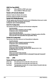
... the Serial Port base address. Realtek LAN Controller [Enabled] [Enabled] Enables the Realtek LAN controller. [Disabled] Disables the Realtek LAN controller. Configuration options: [Enabled] [Disabled] Change Settings [IO=3F8h; IRQ=5,6,7,9,10,11,12] Device Mode [Auto] Allows you to [Enabled] and allows you set the serial port configuration. SPDIF Out Type [SPDIF] [SPDIF] Sets to [SPDIF] for SPDIF audio output. [HDMI] Sets to enable or disable the Rom Help of the Realtek LAN controller. IRQ=5] [IO=378h; Configuration options: [Enabled] [Disabled] Serial Port Configuration...
... the Serial Port base address. Realtek LAN Controller [Enabled] [Enabled] Enables the Realtek LAN controller. [Disabled] Disables the Realtek LAN controller. Configuration options: [Enabled] [Disabled] Change Settings [IO=3F8h; IRQ=5,6,7,9,10,11,12] Device Mode [Auto] Allows you to [Enabled] and allows you set the serial port configuration. SPDIF Out Type [SPDIF] [SPDIF] Sets to [SPDIF] for SPDIF audio output. [HDMI] Sets to enable or disable the Rom Help of the Realtek LAN controller. IRQ=5] [IO=378h; Configuration options: [Enabled] [Disabled] Serial Port Configuration...


