
Series User Manual
Page 4
... (optional for 1200 mm rack rails 3-8 3.2.1 Attaching the cable management arm 3-8 Chapter 4: Motherboard Information 4.1 Z11PG-D24 Series Motherboard layout 4-2 4.2 Jumpers...4-4 4.3 Internal LEDs 4-9 4.4 Internal connectors 4-11 Chapter 5: BIOS Setup 5.1 Managing and updating your BIOS 5-2 5.1.1 ASUS CrashFree BIOS 3 utility 5-2 5.1.2 ASUS EZ Flash Utility 5-3 5.1.3 BUPDATER utility 5-4 5.2 BIOS setup program 5-6 5.2.1 BIOS menu screen 5-7 5.2.2 Menu bar 5-7 5.2.3 Menu items...
... (optional for 1200 mm rack rails 3-8 3.2.1 Attaching the cable management arm 3-8 Chapter 4: Motherboard Information 4.1 Z11PG-D24 Series Motherboard layout 4-2 4.2 Jumpers...4-4 4.3 Internal LEDs 4-9 4.4 Internal connectors 4-11 Chapter 5: BIOS Setup 5.1 Managing and updating your BIOS 5-2 5.1.1 ASUS CrashFree BIOS 3 utility 5-2 5.1.2 ASUS EZ Flash Utility 5-3 5.1.3 BUPDATER utility 5-4 5.2 BIOS setup program 5-6 5.2.1 BIOS menu screen 5-7 5.2.2 Menu bar 5-7 5.2.3 Menu items...
Series User Manual
Page 12
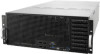
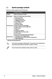
...SATA RAID driver disk. You may have to Chapter 6 for AMD GPU 2 x CPU coolers 1 x Rail Kit 16 x VGA power cables 8 x ASUS CPU 8-pin Power cables 2 x CPU carriers Optional Items One Row SYS FAN (Redundant FAN-Optional) 1 x Redundant Power Supply Module 1 x Trend ... USB floppy drive. If any of the above items is damaged or missing, contact your system package for the following items. ESC8000 G4 Series Chassis ASUS 4U Rackmount Chassis Motherboard ASUS Z11PG-D24 Series Server Board Accessory box 1 x MB Support DVD 1 x ACC instruction card 1 x ASMB9 instruction card 2 x Front PIKE ...
...SATA RAID driver disk. You may have to Chapter 6 for AMD GPU 2 x CPU coolers 1 x Rail Kit 16 x VGA power cables 8 x ASUS CPU 8-pin Power cables 2 x CPU carriers Optional Items One Row SYS FAN (Redundant FAN-Optional) 1 x Redundant Power Supply Module 1 x Trend ... USB floppy drive. If any of the above items is damaged or missing, contact your system package for the following items. ESC8000 G4 Series Chassis ASUS 4U Rackmount Chassis Motherboard ASUS Z11PG-D24 Series Server Board Accessory box 1 x MB Support DVD 1 x ACC instruction card 1 x ASMB9 instruction card 2 x Front PIKE ...

Series User Manual
Page 13
ASUS ESC8000 G4 Series 1-3 1.2 Serial number label Before requesting support from the ASUS Technical Support team, you must take note of the product, ASUS Technical Support team members can then offer a quicker and satisfying solution to your problems. 1 2 3 4 5 6 7 8 2 1 ESC8000 G4 Series xxS0xxxxxxxx The serial number on the ESC8000 G4 Series is printed on the Asset tag. See the figure below. With the correct serial number of the product's serial number containing 12 characters such as xxS0xxxxxxxx.
ASUS ESC8000 G4 Series 1-3 1.2 Serial number label Before requesting support from the ASUS Technical Support team, you must take note of the product, ASUS Technical Support team members can then offer a quicker and satisfying solution to your problems. 1 2 3 4 5 6 7 8 2 1 ESC8000 G4 Series xxS0xxxxxxxx The serial number on the ESC8000 G4 Series is printed on the Asset tag. See the figure below. With the correct serial number of the product's serial number containing 12 characters such as xxS0xxxxxxxx.

Series User Manual
Page 14
The server supports Intel® Xeon® Scalable Processors Family Series plus other latest technologies through the chipsets onboard. Model Name ESC8000 G4 ESC8000 G4/10G Processor / System Bus Core Logic 2 x Socket P0 (LGA 3647) 1st Gen Intel® Xeon® Processor Scalable Family 2nd Gen Intel® Xeon&#...Gen3 x4 link, M.2 supports up to 22110) Intel® RSTe ( Support software RAID 0, 1, 10 & 5) (continued on the next page) 1-4 Chapter 1: Product Introduction 1.3 System specifications The ASUS ESC8000 G4 Series servers features the ASUS Z11PG-D24 Series server board.
The server supports Intel® Xeon® Scalable Processors Family Series plus other latest technologies through the chipsets onboard. Model Name ESC8000 G4 ESC8000 G4/10G Processor / System Bus Core Logic 2 x Socket P0 (LGA 3647) 1st Gen Intel® Xeon® Processor Scalable Family 2nd Gen Intel® Xeon&#...Gen3 x4 link, M.2 supports up to 22110) Intel® RSTe ( Support software RAID 0, 1, 10 & 5) (continued on the next page) 1-4 Chapter 1: Product Introduction 1.3 System specifications The ASUS ESC8000 G4 Series servers features the ASUS Z11PG-D24 Series server board.

Series User Manual
Page 15
... switch/LED 1 x Location switch/LED 1 x Storage Device Access LED 1 x Message LED LAN 1-4 LED Please find the latest OS support from http://www.asus.com/ (continued on the next page) ASUS ESC8000 G4 Series 1-5 Storage bay 3 - 8 support SATA/SAS* drives - Model Name Storage SAS Controller Storage Device Bays Networking LAN Graphic VGA Front I/O Rear I/O Switch/LED...
... switch/LED 1 x Location switch/LED 1 x Storage Device Access LED 1 x Message LED LAN 1-4 LED Please find the latest OS support from http://www.asus.com/ (continued on the next page) ASUS ESC8000 G4 Series 1-5 Storage bay 3 - 8 support SATA/SAS* drives - Model Name Storage SAS Controller Storage Device Bays Networking LAN Graphic VGA Front I/O Rear I/O Switch/LED...

Series User Manual
Page 17
ASUS ESC8000 G4 Series 1-7 Half-length/Low-profile expansion slot Power cord connector and Redundant power supply LAN ports Locate LED Dedicated Management LAN port Full-length/Full-height expansion slots The Dedicated Management LAN port is for the ASUS ASMB9-iKVM only. The power and reset buttons, LED indicators, and USB ports are located on...
ASUS ESC8000 G4 Series 1-7 Half-length/Low-profile expansion slot Power cord connector and Redundant power supply LAN ports Locate LED Dedicated Management LAN port Full-length/Full-height expansion slots The Dedicated Management LAN port is for the ASUS ASMB9-iKVM only. The power and reset buttons, LED indicators, and USB ports are located on...

Series User Manual
Page 18
ASUS Z11PG-D24 Series server Board 3. Riser card with eight full-height/full-length PCIE Expansion slots 6. Connect a USB floppy disk drive to any of fans are optional) 4. 8 x Hot-...
ASUS Z11PG-D24 Series server Board 3. Riser card with eight full-height/full-length PCIE Expansion slots 6. Connect a USB floppy disk drive to any of fans are optional) 4. 8 x Hot-...

Series User Manual
Page 19
... the location switch again to turn off) No LAN connection LAN is transmitting or receiving data LAN connection is normal; 1.7 LED information 1.7.1 Front panel LEDs ESC8000 G4 Series 1 2 3 4 5 6 7 8 2 1 Location button with LED Power button with LED 2 1 LAN2 LED Storage Device LAN1 LED Access LED 2 Mes1sage LED LED Power button with LED Storage Device... ON System power ON OFF Blinking OFF ON OFF ON OFF Blinking ON No activity Read/write data into the storage device System is present ASUS ESC8000 G4 Series 1-9
... the location switch again to turn off) No LAN connection LAN is transmitting or receiving data LAN connection is normal; 1.7 LED information 1.7.1 Front panel LEDs ESC8000 G4 Series 1 2 3 4 5 6 7 8 2 1 Location button with LED Power button with LED 2 1 LAN2 LED Storage Device LAN1 LED Access LED 2 Mes1sage LED LED Power button with LED Storage Device... ON System power ON OFF Blinking OFF ON OFF ON OFF Blinking ON No activity Read/write data into the storage device System is present ASUS ESC8000 G4 Series 1-9

Series User Manual
Page 21
1.7.3 Storage device status LED Red LED Green LED 1 2 3 4 5 6 7 8 2 1 SATA/SAS Storage Device LED Description GREEN ON SATA/SAS storage device power ON RED ON Storage device has failed and should be swapped immediately GREEN/ RED Blinking RAID rebuilding GREEN/ RED Blinking Locate GREEN/ RED OFF Storage device not found GREEN Blinking Read/write data from/into the SATA/SAS storage device ASUS ESC8000 G4 Series 1-11
1.7.3 Storage device status LED Red LED Green LED 1 2 3 4 5 6 7 8 2 1 SATA/SAS Storage Device LED Description GREEN ON SATA/SAS storage device power ON RED ON Storage device has failed and should be swapped immediately GREEN/ RED Blinking RAID rebuilding GREEN/ RED Blinking Locate GREEN/ RED OFF Storage device not found GREEN Blinking Read/write data from/into the SATA/SAS storage device ASUS ESC8000 G4 Series 1-11

Series User Manual
Page 25
... film is pre-attached to the system cover before turning on both sides of the middle chassis cover. 2. Please remove the protection film before shipping. ASUS ESC8000 G4 Series 2-3 To remove the middle chassis cover: 1. Press the cover latches down . 2. Slide the chassis cover towards the front to disengage it from the chassis and...
... film is pre-attached to the system cover before turning on both sides of the middle chassis cover. 2. Please remove the protection film before shipping. ASUS ESC8000 G4 Series 2-3 To remove the middle chassis cover: 1. Press the cover latches down . 2. Slide the chassis cover towards the front to disengage it from the chassis and...

Series User Manual
Page 27
ASUS ESC8000 G4 Series 2-5 Secure the air ducts to the chassis with the four (4) screws removed earlier. To reinstall the air duct: 1. Align and insert the tabs on chassis. 3. Align and reinstall the top and bottom air ducts into the chassis, ensuring that the screw holes on the air ducts match the screw holes on the bottom air duct under the GPU fans. 2.
ASUS ESC8000 G4 Series 2-5 Secure the air ducts to the chassis with the four (4) screws removed earlier. To reinstall the air duct: 1. Align and insert the tabs on chassis. 3. Align and reinstall the top and bottom air ducts into the chassis, ensuring that the screw holes on the air ducts match the screw holes on the bottom air duct under the GPU fans. 2.

Series User Manual
Page 28
ASUS will process Return Merchandise Authorization (RMA) requests only if the motherboard comes with a surface mount LGA 3647 socket designed for the Intel® Xeon® Processor Scalable Family Series. • Ensure that the PnP cap is on the LGA 3647 socket. 2-6 Chapter 2: Hardware Setup Keep the PnP... CPU installation/removal, or misplacement/loss/incorrect removal of the PnP cap. 2.2.1 Installing the CPU and cooler To install a CPU: 1. ASUS will shoulder the cost of repair only if the damage is shipment/ transit-related. • The product warranty does not cover damage to...
ASUS will process Return Merchandise Authorization (RMA) requests only if the motherboard comes with a surface mount LGA 3647 socket designed for the Intel® Xeon® Processor Scalable Family Series. • Ensure that the PnP cap is on the LGA 3647 socket. 2-6 Chapter 2: Hardware Setup Keep the PnP... CPU installation/removal, or misplacement/loss/incorrect removal of the PnP cap. 2.2.1 Installing the CPU and cooler To install a CPU: 1. ASUS will shoulder the cost of repair only if the damage is shipment/ transit-related. • The product warranty does not cover damage to...

Series User Manual
Page 29
... into place (B), and then install the CPU and CPU Carrier into the socket to prevent damaging the CPU pins on top of the CPU sockets. ASUS ESC8000 G4 Series 2-7 Ensure that the triangle mark on the CPU matches the triangle mark on the CPU Carrier (A), install the CPU into the CPU Carrier until it...
... into place (B), and then install the CPU and CPU Carrier into the socket to prevent damaging the CPU pins on top of the CPU sockets. ASUS ESC8000 G4 Series 2-7 Ensure that the triangle mark on the CPU matches the triangle mark on the CPU Carrier (A), install the CPU into the CPU Carrier until it...

Series User Manual
Page 31
The figure illustrates the location of the DDR4 DIMM sockets: ASUS ESC8000 G4 Series 2-9 2.3 System memory 2.3.1 Overview The motherboard comes with 24 Double Data Rate 4 (DDR4) Dual Inline Memory Modules (DIMM) sockets.
The figure illustrates the location of the DDR4 DIMM sockets: ASUS ESC8000 G4 Series 2-9 2.3 System memory 2.3.1 Overview The motherboard comes with 24 Double Data Rate 4 (DDR4) Dual Inline Memory Modules (DIMM) sockets.

Series User Manual
Page 39
... both the motherboard and the components. 1. Press the retaining clip outward to unplug the power supply before adding or removing DIMMs or other system components. ASUS ESC8000 G4 Series 2-17 DIMM slot key Unlocked retaining clip A DIMM is keyed with your fingers when pressing the retaining clips. DO NOT force a DIMM into place and...
... both the motherboard and the components. 1. Press the retaining clip outward to unplug the power supply before adding or removing DIMMs or other system components. ASUS ESC8000 G4 Series 2-17 DIMM slot key Unlocked retaining clip A DIMM is keyed with your fingers when pressing the retaining clips. DO NOT force a DIMM into place and...

Series User Manual
Page 40
... an NVME storage device, ensure to install them to remove the storage device tray. 2-18 Chapter 2: Hardware Setup Press the spring lock. 2. 2.4 Storage devices The ESC8000 G4 Series system supports hot-swap 2.5-inch SATA/SAS/NVME storage devices. Pull the tray lever outwards to the 2 (two) top storage bays. The storage device installed...
... an NVME storage device, ensure to install them to remove the storage device tray. 2-18 Chapter 2: Hardware Setup Press the spring lock. 2. 2.4 Storage devices The ESC8000 G4 Series system supports hot-swap 2.5-inch SATA/SAS/NVME storage devices. Pull the tray lever outwards to the 2 (two) top storage bays. The storage device installed...

Series User Manual
Page 41
... storage device assembly all the way into the storage device tray then secure it clicks and secures the storage device tray in place. 8. Metal beam ASUS ESC8000 G4 Series 2-19 Repeat steps 1 to 7 to the 2 (two) top storage bays. 6. 3.
... storage device assembly all the way into the storage device tray then secure it clicks and secures the storage device tray in place. 8. Metal beam ASUS ESC8000 G4 Series 2-19 Repeat steps 1 to 7 to the 2 (two) top storage bays. 6. 3.

Series User Manual
Page 43
... card (A), then remove the metal bracket from the riser card (B). 4. Before installing an expansion card, read the documentation that came with the screw removed earlier. 6. 3. ASUS ESC8000 G4 Series 2-21 Prepare the expansion card. Remove the screw from the metal bracket on the riser card, then secure the expansion card with it in place.
... card (A), then remove the metal bracket from the riser card (B). 4. Before installing an expansion card, read the documentation that came with the screw removed earlier. 6. 3. ASUS ESC8000 G4 Series 2-21 Prepare the expansion card. Remove the screw from the metal bracket on the riser card, then secure the expansion card with it in place.

Series User Manual
Page 45
... two (2) screw washers to the two screw holes on the ASUS PIKE II card bracket (A), then remove the ASUS PIKE II card bracket (B) from the bottom of the ASUS PIKE II card (B). Prepare the ASUS PIKE II card. 3. ASUS ESC8000 G4 Series 2-23 Remove the two (2) screws on the ASUS PIKE II card (A), then secure the bundled screws to...
... two (2) screw washers to the two screw holes on the ASUS PIKE II card bracket (A), then remove the ASUS PIKE II card bracket (B) from the bottom of the ASUS PIKE II card (B). Prepare the ASUS PIKE II card. 3. ASUS ESC8000 G4 Series 2-23 Remove the two (2) screws on the ASUS PIKE II card (A), then secure the bundled screws to...

Series User Manual
Page 47
Remove the default cable from the backplane (A), then connect the other end of the mini-SAS HD cables from the chassis (B). ASUS ESC8000 G4 Series 2-25 8. Remove the two (2) screws securing the Cache Vault bracket (A), then remove the Cache Vault bracket from the ASUS PIKE II card to the SATA/SAS backplane. Rear view Connect from ASUS PIKE II card slot 1 Connect from ASUS PIKE II card slot 2 Data cable from motherboard Data cable from ASUS PIKE II card 9.
Remove the default cable from the backplane (A), then connect the other end of the mini-SAS HD cables from the chassis (B). ASUS ESC8000 G4 Series 2-25 8. Remove the two (2) screws securing the Cache Vault bracket (A), then remove the Cache Vault bracket from the ASUS PIKE II card to the SATA/SAS backplane. Rear view Connect from ASUS PIKE II card slot 1 Connect from ASUS PIKE II card slot 2 Data cable from motherboard Data cable from ASUS PIKE II card 9.