
User Manual
Page 3
...panel LEDs 1-10 1.8.2 Rear panel LEDs 1-11 1.8.3 LAN (RJ-45) LEDs 1-12 1.8.4 Storage device status LEDs 1-13 Chapter 2: Hardware Setup 2.1 Chassis cover 2-2 2.2 Air ducts...2-7 2.3 Central Processing Unit (CPU 2-9 2.3.1 Installing the CPU and heatsink 2-9 2.4 System memory 2-12 2.4.1 Overview 2-12 2.4.2 Memory configurations 2-13 2.4.3 Installing a DIMM 2-14 2.4.4 Removing a DIMM 2-15 2.5 Storage devices 2-16 2.5.1 Installing a 3.5-inch storage device 2-16 2.5.2 Installing a 2.5-inch storage device 2-18 2.6 Expansion slots 2-19 2.6.1 Installing an expansion card...
...panel LEDs 1-10 1.8.2 Rear panel LEDs 1-11 1.8.3 LAN (RJ-45) LEDs 1-12 1.8.4 Storage device status LEDs 1-13 Chapter 2: Hardware Setup 2.1 Chassis cover 2-2 2.2 Air ducts...2-7 2.3 Central Processing Unit (CPU 2-9 2.3.1 Installing the CPU and heatsink 2-9 2.4 System memory 2-12 2.4.1 Overview 2-12 2.4.2 Memory configurations 2-13 2.4.3 Installing a DIMM 2-14 2.4.4 Removing a DIMM 2-15 2.5 Storage devices 2-16 2.5.1 Installing a 3.5-inch storage device 2-16 2.5.2 Installing a 2.5-inch storage device 2-18 2.6 Expansion slots 2-19 2.6.1 Installing an expansion card...

User Manual
Page 4
... PCIe expansion card slots (on select models 2-25 2.6.5 Installing an OCP 3.0 card to the rear OCP 3.0 socket board (on select models 2-26 2.6.6 (optional) Installing the PFR module 2-26 2.7 Cable connections 2-28 2.7.1 NVMe/SATA/SAS backplane 2-28 2.7.2 GPU SKU board 2-29 2.8 Removable/optional components 2-29 2.8.1 GPU fans 2-30 2.8.2 System fans 2-31 2.8.3 Redundant power supply units 2-32 2.8.4 GPU cards 2-33 2.8.5 GPU bridges 2-36 2.9 Installing optional kits 2-36 Chapter 3: BIOS Setup 3.1 Managing and updating your BIOS 3-2 3.1.1 ASUS CrashFree BIOS 3 utility...
... PCIe expansion card slots (on select models 2-25 2.6.5 Installing an OCP 3.0 card to the rear OCP 3.0 socket board (on select models 2-26 2.6.6 (optional) Installing the PFR module 2-26 2.7 Cable connections 2-28 2.7.1 NVMe/SATA/SAS backplane 2-28 2.7.2 GPU SKU board 2-29 2.8 Removable/optional components 2-29 2.8.1 GPU fans 2-30 2.8.2 System fans 2-31 2.8.3 Redundant power supply units 2-32 2.8.4 GPU cards 2-33 2.8.5 GPU bridges 2-36 2.9 Installing optional kits 2-36 Chapter 3: BIOS Setup 3.1 Managing and updating your BIOS 3-2 3.1.1 ASUS CrashFree BIOS 3 utility...
User Manual
Page 6
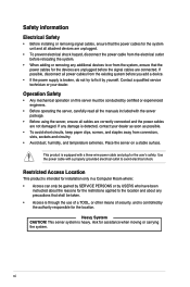
...; Access can only be gained by SERVICE PERSONS or by USERS who have been instructed about any precautions that the power cables for the devices are unplugged before you add a device. • If the power supply is equipped with a properly grounded electrical outlet to fix it by the authority responsible for the location. Safety information Electrical Safety • Before installing or removing signal cables, ensure...
...; Access can only be gained by SERVICE PERSONS or by USERS who have been instructed about any precautions that the power cables for the devices are unplugged before you add a device. • If the power supply is equipped with a properly grounded electrical outlet to fix it by the authority responsible for the location. Safety information Electrical Safety • Before installing or removing signal cables, ensure...

User Manual
Page 7
... general features of configuring a server. Contents This guide contains the following parts: 1. Chapter 4: Driver Installation This chapter provides instructions for installing the necessary drivers for system integrators and experienced users with at least basic knowledge of the server, including sections on front panel and rear panel specifications. 2. Chapter 3: BIOS Setup This chapter tells how to perform when installing or removing system components. 3. About this guide Audience This user guide is intended for...
... general features of configuring a server. Contents This guide contains the following parts: 1. Chapter 4: Driver Installation This chapter provides instructions for installing the necessary drivers for system integrators and experienced users with at least basic knowledge of the server, including sections on front panel and rear panel specifications. 2. Chapter 3: BIOS Setup This chapter tells how to perform when installing or removing system components. 3. About this guide Audience This user guide is intended for...

User Manual
Page 8
... trying to complete a task. ASUS websites The ASUS websites provide updated information for product and software updates. 1. If you must press two or more information. ASUS Control Center (ACC) user guide This manual tells how to help you complete a task. NOTE: Tips and additional information to set up and use the proprietary ASUS server management utility. 2. Typography Bold text Italics ++ Command Indicates a menu or an item to emphasize...
... trying to complete a task. ASUS websites The ASUS websites provide updated information for product and software updates. 1. If you must press two or more information. ASUS Control Center (ACC) user guide This manual tells how to help you complete a task. NOTE: Tips and additional information to set up and use the proprietary ASUS server management utility. 2. Typography Bold text Italics ++ Command Indicates a menu or an item to emphasize...

User Manual
Page 13
... SAS support requires an optional HBA/RAID card Backplane 8 x MCIO connectors for NVMe Connectors 2 x Mini SAS HD for 8 x SATA Motherboard Connectors 4 x MCIO connectors (x8 link) for PCIe slots or NVMe Default Cables 2 x backplane MCIO cables LAN 1 x Dual Port Intel® I350 1GbE/X710-AT2 10GbE LAN controller 1 x Management Port Aspeed AST2600 64MB Up to 8 double-deck GPU cards 2 x USB 3.2 Gen1 ports 1 x VGA Port 1 x COM port 2 x RJ-45 LAN ports 1 x RJ-45 Management LAN port Front: Rear: 1 x Power switch/LED 1 x Location switch/LED 1 x Q-Code/Port 80 LED 1 x Clear CMOS...
... SAS support requires an optional HBA/RAID card Backplane 8 x MCIO connectors for NVMe Connectors 2 x Mini SAS HD for 8 x SATA Motherboard Connectors 4 x MCIO connectors (x8 link) for PCIe slots or NVMe Default Cables 2 x backplane MCIO cables LAN 1 x Dual Port Intel® I350 1GbE/X710-AT2 10GbE LAN controller 1 x Management Port Aspeed AST2600 64MB Up to 8 double-deck GPU cards 2 x USB 3.2 Gen1 ports 1 x VGA Port 1 x COM port 2 x RJ-45 LAN ports 1 x RJ-45 Management LAN port Front: Rear: 1 x Power switch/LED 1 x Location switch/LED 1 x Q-Code/Port 80 LED 1 x Clear CMOS...
User Manual
Page 15
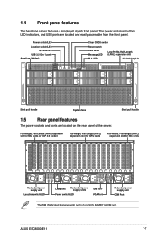
...) port is for ASUS ASMB11-iKVM only. ASUS ESC8000-E11 1-7 1.4 Front panel features The barebone server features a simple yet stylish front panel. The power and reset buttons, LED indicators, and USB ports are located on the rear panel of the server. Power switch/LED Location switch/LED Q-Code LED USB 3.2 Gen 1 ports Asset tag (hidden) Clear CMOS switch Reset switch LAN LEDs Message LED Low-Profile, Half-Length (LPHL) expansion slot M.2 LED 3.5-inch bay 1-8 Q code CLEAR CMOS RESET LAN 1 LAN 2 M.2 Q code CLEAR CMOS RESET LAN 1 LAN 2 M.2 Steel pull handle System fans...
...) port is for ASUS ASMB11-iKVM only. ASUS ESC8000-E11 1-7 1.4 Front panel features The barebone server features a simple yet stylish front panel. The power and reset buttons, LED indicators, and USB ports are located on the rear panel of the server. Power switch/LED Location switch/LED Q-Code LED USB 3.2 Gen 1 ports Asset tag (hidden) Clear CMOS switch Reset switch LAN LEDs Message LED Low-Profile, Half-Length (LPHL) expansion slot M.2 LED 3.5-inch bay 1-8 Q code CLEAR CMOS RESET LAN 1 LAN 2 M.2 Q code CLEAR CMOS RESET LAN 1 LAN 2 M.2 Steel pull handle System fans...

User Manual
Page 17
... power supply units (hidden) 2. GPU fans 4. ASUS Z13PG-D32 server board 5. Connect a USB floppy disk drive to use a floppy disk. Asset tag (hidden) 8. PCIe riser card with full-height/full-length PCIe expansion slots 3. Remove the protection film before shipping. A protection film is pre-attached to the front cover before turning on the front or rear panel if you need to any of the USB ports on the system for sufficient heat dissipation. *WARNING* HAZARDOUS MOVING PARTS...
... power supply units (hidden) 2. GPU fans 4. ASUS Z13PG-D32 server board 5. Connect a USB floppy disk drive to use a floppy disk. Asset tag (hidden) 8. PCIe riser card with full-height/full-length PCIe expansion slots 3. Remove the protection film before shipping. A protection film is pre-attached to the front cover before turning on the front or rear panel if you need to any of the USB ports on the system for sufficient heat dissipation. *WARNING* HAZARDOUS MOVING PARTS...

User Manual
Page 47
PCIe Gen5 x8 link FH, FL slot for NIC cards PCIe Gen5 x16 link FH, FL slot for NIC cards 1. ASUS ESC8000-E11 2-25 Remove the screws from the metal cover, then remove the metal cover. 3. 2.6.4 Installing an expansion card to the rear PCIe expansion card slots (on select models) Follow the below instructions to install an expansion card to the rear PCIe expansion card slots. Align and insert the golden fingers of the PCIe card into the PCIe slot, then secure it using the screw removed earlier.
PCIe Gen5 x8 link FH, FL slot for NIC cards PCIe Gen5 x16 link FH, FL slot for NIC cards 1. ASUS ESC8000-E11 2-25 Remove the screws from the metal cover, then remove the metal cover. 3. 2.6.4 Installing an expansion card to the rear PCIe expansion card slots (on select models) Follow the below instructions to install an expansion card to the rear PCIe expansion card slots. Align and insert the golden fingers of the PCIe card into the PCIe slot, then secure it using the screw removed earlier.

User Manual
Page 69
...: [Disabled] [Enabled] 3.4.3 Redfish Host Interface Settings Redfish [Disabled] Configuration options: [Disabled] [Enabled] The following items appear only when Redfish is set to select the authentication mode. IP Mask address Allows you to enter the IP address. Configuration options: [Basic Authentication] [Session Authentication] IP address Allows you to enter the IP Port. 3.4.4 Onboard LAN Configuration Onboard I350/X710 LAN Configuration LAN1/LAN2 LAN Enable [LAN1, LAN2 Enabled] Configuration options: [Disabled] [LAN1 Enabled Only] [LAN1, LAN2 Enabled] ASUS ESC8000-E11 3-11...
...: [Disabled] [Enabled] 3.4.3 Redfish Host Interface Settings Redfish [Disabled] Configuration options: [Disabled] [Enabled] The following items appear only when Redfish is set to select the authentication mode. IP Mask address Allows you to enter the IP address. Configuration options: [Basic Authentication] [Session Authentication] IP address Allows you to enter the IP Port. 3.4.4 Onboard LAN Configuration Onboard I350/X710 LAN Configuration LAN1/LAN2 LAN Enable [LAN1, LAN2 Enabled] Configuration options: [Disabled] [LAN1 Enabled Only] [LAN1, LAN2 Enabled] ASUS ESC8000-E11 3-11...

User Manual
Page 70
... require lower speeds. The settings specify how the host computer and the remote computer (which the user is set to [Enabled]. Terminal Type [ANSI] Allows you to set the terminal type. [VT100] ASCII char set. [VT100Plus] Extends VT100 to support color, function keys, etc. [VT-UTF8]Uses UTF8 encoding to enable or disable the console redirection feature. Configuration options: [9600] [19200] [38400] [57600] [115200] Data Bits [8] Configuration options: [7] [8] 3-12 Chapter 3: BIOS Setup The speed...
... require lower speeds. The settings specify how the host computer and the remote computer (which the user is set to [Enabled]. Terminal Type [ANSI] Allows you to set the terminal type. [VT100] ASCII char set. [VT100Plus] Extends VT100 to support color, function keys, etc. [VT-UTF8]Uses UTF8 encoding to enable or disable the console redirection feature. Configuration options: [9600] [19200] [38400] [57600] [115200] Data Bits [8] Configuration options: [7] [8] 3-12 Chapter 3: BIOS Setup The speed...

User Manual
Page 72
... be sent to [Enabled]. Hardware flow control uses two wires to re-start " signal can prevent data loss from buffer overflow. Console Redirection Settings Out-of-Band Mgmt Port [COM1] Microsoft Windows Emergency Management Services (EMS) allow for remote management of -Band Management/ Windows Emergency Management Services (EMS) Console Redirection EMS [Enabled] Allows you to enable or disable the console redirection feature. Configuration options: [None] [Hardware RTS/CTS] [Software Xon/Xoff] 3-14 Chapter 3: BIOS Setup The next best...
... be sent to [Enabled]. Hardware flow control uses two wires to re-start " signal can prevent data loss from buffer overflow. Console Redirection Settings Out-of-Band Mgmt Port [COM1] Microsoft Windows Emergency Management Services (EMS) allow for remote management of -Band Management/ Windows Emergency Management Services (EMS) Console Redirection EMS [Enabled] Allows you to enable or disable the console redirection feature. Configuration options: [None] [Hardware RTS/CTS] [Software Xon/Xoff] 3-14 Chapter 3: BIOS Setup The next best...

User Manual
Page 73
... unwanted side effects. DMA;] [IO=3E8h; Configuration options: [Use Automatic Settings] [IO=3F8h; IRQ=4; IRQ=3, 4, 5, 7, 9, 10, 11, 12; DMA;] [IO=2E8h; DMA;] ASUS ESC8000-E11 3-15 PROCEED WITH CAUTION. Configuration options: [Disabled] [Enabled] The following item appears only when Use This Device is set basic properties of the control, reflects the current Logical Device state. Changes made during Setup Session will be shown after system restarts...
... unwanted side effects. DMA;] [IO=3E8h; Configuration options: [Use Automatic Settings] [IO=3F8h; IRQ=4; IRQ=3, 4, 5, 7, 9, 10, 11, 12; DMA;] [IO=2E8h; DMA;] ASUS ESC8000-E11 3-15 PROCEED WITH CAUTION. Configuration options: [Disabled] [Enabled] The following item appears only when Use This Device is set basic properties of the control, reflects the current Logical Device state. Changes made during Setup Session will be shown after system restarts...

User Manual
Page 78
... become user-configurable with set to [Last State], the system goes into off or on state, whatever the system state was before the AC power loss. Configuration options: [Power Off] [Power On] [Last State] Power On By PCI-E [Disabled] [Disabled] Disables wake events from PCI-E devices. [Enabled] Enables wake evens from PCI-E devices. When set values. 3-20 Chapter 3: BIOS Setup Restore AC Power Loss [Last State] When set to [Power On], the system will reboot after...
... become user-configurable with set to [Last State], the system goes into off or on state, whatever the system state was before the AC power loss. Configuration options: [Power Off] [Power On] [Last State] Power On By PCI-E [Disabled] [Disabled] Disables wake events from PCI-E devices. [Enabled] Enables wake evens from PCI-E devices. When set values. 3-20 Chapter 3: BIOS Setup Restore AC Power Loss [Last State] When set to [Power On], the system will reboot after...

User Manual
Page 82
Configuration options: [Auto] [Onboard Device] [PCIE Device] 3-24 Chapter 3: BIOS Setup Configuration options: [Disabled] [Enabled in S5] IEH Mode [Enabled] Allows you to configure the DeepSx power policy. DeepSx Power Policies [Disabled] Allows you to enable or bypass Interrupt Error Handling (IEH). Configuration options: [Bypass Mode] [Enabled] 3.5.2 Miscellaneous Configuration Active Video [Auto] Allows you to configure SATA and RST settings. 3.5.1 PCH-IO Configuration SATA And RST Configuration Allows you to select the active video type.
Configuration options: [Auto] [Onboard Device] [PCIE Device] 3-24 Chapter 3: BIOS Setup Configuration options: [Disabled] [Enabled in S5] IEH Mode [Enabled] Allows you to configure the DeepSx power policy. DeepSx Power Policies [Disabled] Allows you to enable or bypass Interrupt Error Handling (IEH). Configuration options: [Bypass Mode] [Enabled] 3.5.2 Miscellaneous Configuration Active Video [Auto] Allows you to configure SATA and RST settings. 3.5.1 PCH-IO Configuration SATA And RST Configuration Allows you to select the active video type.

User Manual
Page 84
Configuration options: [Disable] [Enable] The following item is available only when System Errors is set to configure Whea settings. 3-26 Chapter 3: BIOS Setup Whea Settings Allows you to enable or disable System Errors setup options. 3.5.4 Runtime Error Logging Support System Errors [Enable] Allows you to [Enabled].
Configuration options: [Disable] [Enable] The following item is available only when System Errors is set to configure Whea settings. 3-26 Chapter 3: BIOS Setup Whea Settings Allows you to enable or disable System Errors setup options. 3.5.4 Runtime Error Logging Support System Errors [Enable] Allows you to [Enabled].

User Manual
Page 92
... increase boot speed on cold boots. Portions of memory reference code will be run at frequencies higher than the memory supports (limited by processor support). Configuration options: [Auto] [3200] [3600] [4000] [4400] [4800] Sockets in parallel. If this item is disabled, system memory can be skipped when possible to enable or disable fast boot. Configuration options: [Disabled] [Enabled] 3-34 Chapter 3: BIOS Setup Configuration options: [All] [1] [2] [4] Attempt Fast Boot [Enabled] Allows you to set the maximum memory...
... increase boot speed on cold boots. Portions of memory reference code will be run at frequencies higher than the memory supports (limited by processor support). Configuration options: [Auto] [3200] [3600] [4000] [4400] [4800] Sockets in parallel. If this item is disabled, system memory can be skipped when possible to enable or disable fast boot. Configuration options: [Disabled] [Enabled] 3-34 Chapter 3: BIOS Setup Configuration options: [All] [1] [2] [4] Attempt Fast Boot [Enabled] Allows you to set the maximum memory...

User Manual
Page 93
Configuration options: [Disabled] [Enabled] Enable ADR [Enabled] Allows you to configure memory RAS settings. Configuration options: [Disabled] [Enabled] ASUS ESC8000-E11 3-35 Configuration options: [Disabled] [Enabled] Outlier Check Disable [Enabled] Configuration options: [Disabled] [Enabled] Memory Topology Displays memory topology with DIMM population information. PMem Configuration Allows you to configure PMem settings. 3.6.5 IIO Configuration Intel(R) VT for Directed I/O (VT-d) Intel(R) VT for Directed I/O (VT-d) [Enabled] Allows you to enable or disable the Intel Virtualization...
Configuration options: [Disabled] [Enabled] Enable ADR [Enabled] Allows you to configure memory RAS settings. Configuration options: [Disabled] [Enabled] ASUS ESC8000-E11 3-35 Configuration options: [Disabled] [Enabled] Outlier Check Disable [Enabled] Configuration options: [Disabled] [Enabled] Memory Topology Displays memory topology with DIMM population information. PMem Configuration Allows you to configure PMem settings. 3.6.5 IIO Configuration Intel(R) VT for Directed I/O (VT-d) Intel(R) VT for Directed I/O (VT-d) [Enabled] Allows you to enable or disable the Intel Virtualization...

User Manual
Page 96
...: [Disabled] [Enabled] Secure Boot Mode [Custom] Allows you to load the default secure boot keys. Clear Secure Boot Keys Allows you to configure Key Management options. 3-38 Chapter 3: BIOS Setup To change a user password: 1. Select Yes from the Warning message window, then press . User Password To set the Secure Boot selector. From the Enter Current Password box, key in a new password, then press . 4. From the Create New Password box, key in the current password, then press . 3. Configuration options: [Standard] [Custom] Install Default Secure Boot Keys Allows...
...: [Disabled] [Enabled] Secure Boot Mode [Custom] Allows you to load the default secure boot keys. Clear Secure Boot Keys Allows you to configure Key Management options. 3-38 Chapter 3: BIOS Setup To change a user password: 1. Select Yes from the Warning message window, then press . User Password To set the Secure Boot selector. From the Enter Current Password box, key in a new password, then press . 4. From the Create New Password box, key in the current password, then press . 3. Configuration options: [Standard] [Custom] Install Default Secure Boot Keys Allows...

User Manual
Page 107
... RC end Memory already installed. NB Init. CSM Init. AMI USB Driver Init. AMI USB Driver Init. DXE Initial Program Load(IPL) DXE Core Started DXE NVRAM Init. NB Init. PCI Bus Enumeration. Console outout connect event Console input connect event AMI Super IO start BIOS Setup Utility input wait Ready to boot event Legacy boot event APIC mode PIC mode ASUS ESC8000-E11 3 IDE, AHCI Init. Action Normal boot PHASE POST CODE BB BC BF 5A PEI(Pre-EFI initialization) phase...
... RC end Memory already installed. NB Init. CSM Init. AMI USB Driver Init. AMI USB Driver Init. DXE Initial Program Load(IPL) DXE Core Started DXE NVRAM Init. NB Init. PCI Bus Enumeration. Console outout connect event Console input connect event AMI Super IO start BIOS Setup Utility input wait Ready to boot event Legacy boot event APIC mode PIC mode ASUS ESC8000-E11 3 IDE, AHCI Init. Action Normal boot PHASE POST CODE BB BC BF 5A PEI(Pre-EFI initialization) phase...


