
User Manual
Page 3
...features 1-6 1.7 LED information 1-7 1.7.1 Front panel LEDs 1-7 1.7.2 Rear panel LEDs 1-8 1.7.3 LAN (RJ-45) LEDs 1-9 1.7.4 HDD status LEDs 1-10 1.7.5 Q-Code table 1-11 Chapter 2: Hardware Setup 2.1 Chassis cover 2-2 2.1.1 Air duct 2-4 2.2 Central Processing Unit (CPU 2-5 2.2.1 Installing the CPU ...and heatsink 2-5 2.3 System memory 2-9 2.3.1 Overview 2-9 2.3.2 Memory Configurations 2-10 2.4 Storage devices 2-12 2.4.1 Installing a 3.5-inch SATA/SAS storage device 2-12 2.4.2 Installing a 2.5-inch SATA/SAS/NVMe storage...
...features 1-6 1.7 LED information 1-7 1.7.1 Front panel LEDs 1-7 1.7.2 Rear panel LEDs 1-8 1.7.3 LAN (RJ-45) LEDs 1-9 1.7.4 HDD status LEDs 1-10 1.7.5 Q-Code table 1-11 Chapter 2: Hardware Setup 2.1 Chassis cover 2-2 2.1.1 Air duct 2-4 2.2 Central Processing Unit (CPU 2-5 2.2.1 Installing the CPU ...and heatsink 2-5 2.3 System memory 2-9 2.3.1 Overview 2-9 2.3.2 Memory Configurations 2-10 2.4 Storage devices 2-12 2.4.1 Installing a 3.5-inch SATA/SAS storage device 2-12 2.4.2 Installing a 2.5-inch SATA/SAS/NVMe storage...

User Manual
Page 4
... connectors 3-11 3.6 Onboard LEDs 3-20 Chapter 4: BIOS Setup 4.1 Managing and updating your BIOS 4-2 4.1.1 ASUS CrashFree BIOS 3 utility 4-2 4.1.2 ASUS EZ Flash Utility 4-3 4.1.3 BUPDATER utility 4-4 4.2 BIOS setup program 4-6 4.2.1 BIOS menu screen 4-7 4.2.2 Menu bar 4-7 4.3 Main menu 4-9 4.4 Advanced menu 4-10 4.4.1 Trusted Computing 4-10 4.4.2 AMD CBS 4-10 4.4.3 Onboard LAN Configuration 4-17 4.4.4 Serial Port Console Redirection 4-18 4.4.5 CPU Configuration 4-20 4.4.6 PCI...
... connectors 3-11 3.6 Onboard LEDs 3-20 Chapter 4: BIOS Setup 4.1 Managing and updating your BIOS 4-2 4.1.1 ASUS CrashFree BIOS 3 utility 4-2 4.1.2 ASUS EZ Flash Utility 4-3 4.1.3 BUPDATER utility 4-4 4.2 BIOS setup program 4-6 4.2.1 BIOS menu screen 4-7 4.2.2 Menu bar 4-7 4.3 Main menu 4-9 4.4 Advanced menu 4-10 4.4.1 Trusted Computing 4-10 4.4.2 AMD CBS 4-10 4.4.3 Onboard LAN Configuration 4-17 4.4.4 Serial Port Console Redirection 4-18 4.4.5 CPU Configuration 4-20 4.4.6 PCI...

User Manual
Page 5
Contents 4.4.9 NVMe Configuration 4-24 4.4.10 SATA Configuration 4-24 4.4.11 APM Configuration 4-24 4.4.12 AMD Mem Configuration Status 4-25 4.4.13 T1s Auth 4-25 4.4.14 Driver Health 4-26 4.5 Chipset menu 4-26 4.6 Security menu 4-27 4.7 Boot menu 4-30 4.8 Tool menu 4-31 4.9 Event Logs menu 4-32 4.9.1 Change Smbios Event Log Settings 4-32 4.9.2 View Smbios Event Log 4-33 4.10 Server Mgmt menu 4-34 4.11 Exit menu 4-37 Chapter 5: Driver Installation 5.1 Running the Support DVD 5-2 Appendix K14PG-U12 block diagram A-2 Notices ...A-3 Service and Support A-6 v
Contents 4.4.9 NVMe Configuration 4-24 4.4.10 SATA Configuration 4-24 4.4.11 APM Configuration 4-24 4.4.12 AMD Mem Configuration Status 4-25 4.4.13 T1s Auth 4-25 4.4.14 Driver Health 4-26 4.5 Chipset menu 4-26 4.6 Security menu 4-27 4.7 Boot menu 4-30 4.8 Tool menu 4-31 4.9 Event Logs menu 4-32 4.9.1 Change Smbios Event Log Settings 4-32 4.9.2 View Smbios Event Log 4-33 4.10 Server Mgmt menu 4-34 4.11 Exit menu 4-37 Chapter 5: Driver Installation 5.1 Running the Support DVD 5-2 Appendix K14PG-U12 block diagram A-2 Notices ...A-3 Service and Support A-6 v

User Manual
Page 14
... Rear I/O ports Switch/LED Security OS Support Out of Band Management Remote Solution Hardware Software Dimension Net Weight Kg Gross Weight Kg Power Supply Environment ESC4000A-E12 2 x Gigabit LAN ports (Intel® I350) 1 x Dedicated Management port AST2600 64MB Up to 4 dual-slot or 8 single-slot GPU cards 4 x USB ...KVM-over-IP ASUS Control Center 800mm x 439.5mm x 88.9mm (2U) 31.50" x 17.30" x 3.5" 24 kg (excluding CPU, DRAM, and HDD) 33 kg (including packing, excluding CPU, DRAM, and HDD) 1+1 Redundant 2600W 80 PLUS Titanium CRPS-R Power Supply Operation temperature: 10° ~ ...
... Rear I/O ports Switch/LED Security OS Support Out of Band Management Remote Solution Hardware Software Dimension Net Weight Kg Gross Weight Kg Power Supply Environment ESC4000A-E12 2 x Gigabit LAN ports (Intel® I350) 1 x Dedicated Management port AST2600 64MB Up to 4 dual-slot or 8 single-slot GPU cards 4 x USB ...KVM-over-IP ASUS Control Center 800mm x 439.5mm x 88.9mm (2U) 31.50" x 17.30" x 3.5" 24 kg (excluding CPU, DRAM, and HDD) 33 kg (including packing, excluding CPU, DRAM, and HDD) 1+1 Redundant 2600W 80 PLUS Titanium CRPS-R Power Supply Operation temperature: 10° ~ ...
User Manual
Page 19
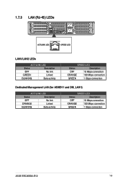
2 1 1.7.3 LAN (RJ-45) LEDs DM 1 2 ACT/LINK LED SPEED LED LAN1/LAN2 LEDs ACT/LINK LED Status Description OFF No link GREEN Linked BLINKING Data activity SPEED LED Status Description OFF 10 Mbps connection ORANGE 100 Mbps connection GREEN 1 Gbps connection Dedicated Management LAN (for ASMB11 and DM_LAN1) ACT/LINK LED Status Description OFF No link ORANGE Linked BLINKING Data activity SPEED LED Status Description OFF 10 Mbps connection ORANGE 100 Mbps connection GREEN 1 Gbps connection ASUS ESC4000A-E12 1-9
2 1 1.7.3 LAN (RJ-45) LEDs DM 1 2 ACT/LINK LED SPEED LED LAN1/LAN2 LEDs ACT/LINK LED Status Description OFF No link GREEN Linked BLINKING Data activity SPEED LED Status Description OFF 10 Mbps connection ORANGE 100 Mbps connection GREEN 1 Gbps connection Dedicated Management LAN (for ASMB11 and DM_LAN1) ACT/LINK LED Status Description OFF No link ORANGE Linked BLINKING Data activity SPEED LED Status Description OFF 10 Mbps connection ORANGE 100 Mbps connection GREEN 1 Gbps connection ASUS ESC4000A-E12 1-9

User Manual
Page 20
1.7.4 HDD status LEDs Red LED Green LED 2 1 Storage Device LED Description Status (RED) ON Blinking Storage device has failed RADM ID rebuilding or locating ON Storage1 de2 vice power ON Activity (GREEN) Blinking Read/write data from/into the SATA/SAS/NVME storage device OFF Storage device not found 1-10 Chapter 1: Product Introduction
1.7.4 HDD status LEDs Red LED Green LED 2 1 Storage Device LED Description Status (RED) ON Blinking Storage device has failed RADM ID rebuilding or locating ON Storage1 de2 vice power ON Activity (GREEN) Blinking Read/write data from/into the SATA/SAS/NVME storage device OFF Storage device not found 1-10 Chapter 1: Product Introduction

User Manual
Page 34
... screw , then fully tighten screw . C. A torque value of 12.5±2.5kg-cm (11.0±2.1 lbf-in) is shown both in order from to the motherboard. 10. For more information, refer to the motherboard. B. The below and on the CPU socket and make sure the heatsink screws are T20 models. Fully tighten...
... screw , then fully tighten screw . C. A torque value of 12.5±2.5kg-cm (11.0±2.1 lbf-in) is shown both in order from to the motherboard. 10. For more information, refer to the motherboard. B. The below and on the CPU socket and make sure the heatsink screws are T20 models. Fully tighten...

User Manual
Page 36
...8226; 4 DIMMs • • • • 6 DIMMs • • • ••• 8 DIMMs • • • • ••• • 10 DIMMs 12 DIMMs Installing a DIMM on the socket. Align a DIMM on the socket such that it is keyed with the same CAS latency. For optimum...in only one direction. DO NOT force a DIMM into the DIMM sockets using the memory configurations in this section. • Refer to ASUS Server AVL for the updated list of compatible DIMMs. • Always install DIMMs with a notch so that the notch on the DIMM...
...8226; 4 DIMMs • • • • 6 DIMMs • • • ••• 8 DIMMs • • • • ••• • 10 DIMMs 12 DIMMs Installing a DIMM on the socket. Align a DIMM on the socket such that it is keyed with the same CAS latency. For optimum...in only one direction. DO NOT force a DIMM into the DIMM sockets using the memory configurations in this section. • Refer to ASUS Server AVL for the updated list of compatible DIMMs. • Always install DIMMs with a notch so that the notch on the DIMM...

User Manual
Page 46
3. Remove the ten (10) screws as shown, then remove the two (2) fans and fan cages from the system chassis. 4. Remove the fan cage from the system chassis. 2-20 Chapter 2: Hardware Setup
3. Remove the ten (10) screws as shown, then remove the two (2) fans and fan cages from the system chassis. 4. Remove the fan cage from the system chassis. 2-20 Chapter 2: Hardware Setup

User Manual
Page 54
Align and install the two (2) fans and fan cages, then secure it using the two screws removed earlier. 11. (Optional) Refer to the Installing the Cache Vault Power Module section to install and connect the Cache Vault Power Module. 10. The cache vault is required for the PIKE II 3108 card or the 9560 RAID card. 12. Secure the internal bracket using the ten (10) screws removed previously. 2-28 Chapter 2: Hardware Setup
Align and install the two (2) fans and fan cages, then secure it using the two screws removed earlier. 11. (Optional) Refer to the Installing the Cache Vault Power Module section to install and connect the Cache Vault Power Module. 10. The cache vault is required for the PIKE II 3108 card or the 9560 RAID card. 12. Secure the internal bracket using the ten (10) screws removed previously. 2-28 Chapter 2: Hardware Setup

User Manual
Page 62
...4* 12 Communications Port (COM1) 5* 13 -- 6 14 Floppy Disk Controller 7* 15 -- 8 3 System CMOS/Real Time Clock 9* 4 ACPI Mode when used 10* 5 IRQ Holder for PCI Steering 11* 6 IRQ Holder for PCI Steering 12* 7 PS/2 Compatible Mouse Port 13 8 Numeric Data Processor 14* 9 Primary ...IDE Channel 15* 10 Secondary IDE Channel * These IRQs are usually available for the expansion card. Assign an IRQ to the card. Standard Interrupt assignments IRQ ...
...4* 12 Communications Port (COM1) 5* 13 -- 6 14 Floppy Disk Controller 7* 15 -- 8 3 System CMOS/Real Time Clock 9* 4 ACPI Mode when used 10* 5 IRQ Holder for PCI Steering 11* 6 IRQ Holder for PCI Steering 12* 7 PS/2 Compatible Mouse Port 13 8 Numeric Data Processor 14* 9 Primary ...IDE Channel 15* 10 Secondary IDE Channel * These IRQs are usually available for the expansion card. Assign an IRQ to the card. Standard Interrupt assignments IRQ ...

User Manual
Page 72
Ensure the card is completely seated on a flat and stable surface. 8. Replace the metal covers for any unused PCIe slots, then secure the PCIe lock using the two thumbscrews. 12. Place the GPU bracket on the slot. 11. Secure the air duct and GPU assembly with a screw. 2-46 Chapter 2: Hardware Setup Insert the GPU cables into the card slot on the bracket. 10. 7. Loosen the two thumbscrews and remove the PCIe lock (A), then remove the metal covers (B). 9. Align and insert the golden fingers of the GPU into the opening on the bracket.
Ensure the card is completely seated on a flat and stable surface. 8. Replace the metal covers for any unused PCIe slots, then secure the PCIe lock using the two thumbscrews. 12. Place the GPU bracket on the slot. 11. Secure the air duct and GPU assembly with a screw. 2-46 Chapter 2: Hardware Setup Insert the GPU cables into the card slot on the bracket. 10. 7. Loosen the two thumbscrews and remove the PCIe lock (A), then remove the metal covers (B). 9. Align and insert the golden fingers of the GPU into the opening on the bracket.

User Manual
Page 80
... system passwords. Plug the power cord and turn ON the computer. 4. Except when clearing the RTC RAM, never remove the cap on pins 2-3 for about 5-10 seconds, then move the jumper again to clear the CMOS RTC RAM data. To erase the RTC RAM: 1. 3.4 Jumpers 1. Move the jumper cap from pins...
... system passwords. Plug the power cord and turn ON the computer. 4. Except when clearing the RTC RAM, never remove the cap on pins 2-3 for about 5-10 seconds, then move the jumper again to clear the CMOS RTC RAM data. To erase the RTC RAM: 1. 3.4 Jumpers 1. Move the jumper cap from pins...

User Manual
Page 82
4. DMLAN setting (3-pin DM_IP_SEL1) This jumper allows you to select which protocol in the GPU sensor to select the DMLAN setting. IPMI SW setting (3-pin IPMI_SW1) This jumper allows you to function. 3-8 Chapter 3: Motherboard Information Set to pins 2-3 to force the DMLAN IP to static mode (IP=10.10.10.10, submask=255.255.255.0). 5.
4. DMLAN setting (3-pin DM_IP_SEL1) This jumper allows you to select which protocol in the GPU sensor to select the DMLAN setting. IPMI SW setting (3-pin IPMI_SW1) This jumper allows you to function. 3-8 Chapter 3: Motherboard Information Set to pins 2-3 to force the DMLAN IP to static mode (IP=10.10.10.10, submask=255.255.255.0). 5.

User Manual
Page 84
PSU_ALT1 (3-pin PSU_ALT1) This jumper allows you to enable or disable the PSU SMB alert. 3-10 Chapter 3: Motherboard Information 8.
PSU_ALT1 (3-pin PSU_ALT1) This jumper allows you to enable or disable the PSU SMB alert. 3-10 Chapter 3: Motherboard Information 8.

User Manual
Page 87
5. ASUS ESC4000A-E12 3-13 Connect the serial port module cable to one of these connectors, then install the module to a slot opening at the back of the system chassis. 6. TPM connector (14-1 pin TPM1) This connector supports a Trusted Platform Module (TPM) system, which can securely store keys, digital certificates, passwords, and data. Serial Port connector (10-1 pin COM1) This connector is for the serial COM port.
5. ASUS ESC4000A-E12 3-13 Connect the serial port module cable to one of these connectors, then install the module to a slot opening at the back of the system chassis. 6. TPM connector (14-1 pin TPM1) This connector supports a Trusted Platform Module (TPM) system, which can securely store keys, digital certificates, passwords, and data. Serial Port connector (10-1 pin COM1) This connector is for the serial COM port.

User Manual
Page 91
ASUS ESC4000A-E12 3-17 10. BMC Debug UART connector (3-pin BMC_DEBUGUART1) This connector is used for reading the BMC UART Debug log.
ASUS ESC4000A-E12 3-17 10. BMC Debug UART connector (3-pin BMC_DEBUGUART1) This connector is used for reading the BMC UART Debug log.

User Manual
Page 99
... keys to use a DOS‑based utility. Press and select Yes to the Drive field. 4. ASUS Tek. Ensure to load the BIOS default settings to prevent system boot failure! ASUS ESC4000A-E12 4-3 Enter the BIOS setup program. Reboot the system when the update process is done. • ... to switch to the Tool menu, then select Start ASUS EZ Flash. EzFlash Utility Current Platform Platform : K14PG-U12 Version : 0102 Build Date : 04/01/2022 New Platform Platform : K14PG-U12 Version : 0104 Build Date : 10/27/2022 FS0 System Volume Information K14PG-U12 BIOS Windows...
... keys to use a DOS‑based utility. Press and select Yes to the Drive field. 4. ASUS Tek. Ensure to load the BIOS default settings to prevent system boot failure! ASUS ESC4000A-E12 4-3 Enter the BIOS setup program. Reboot the system when the update process is done. • ... to switch to the Tool menu, then select Start ASUS EZ Flash. EzFlash Utility Current Platform Platform : K14PG-U12 Version : 0102 Build Date : 04/01/2022 New Platform Platform : K14PG-U12 Version : 0104 Build Date : 10/27/2022 FS0 System Volume Information K14PG-U12 BIOS Windows...

User Manual
Page 101
DO NOT SHUTDOWN THE SYSTEM!!! The utility returns to prevent system boot failure! 5. The BIOS update is completed. Please restart your system. C:\> ASUS ESC4000A-E12 4-5 ASUS Tek. Write 75% DO NOT shut down or reset the system while updating the BIOS to the DOS prompt after the BIOS update process is ... BIOS file. 4. EzFlash Utility Current Platform Platform : K14PG-U12 Version : 0102 Build date: 04/01/2022 New Platform Platform : K14PG-U12 Version : 0104 Build date: 10/27/2022 Start Programming Flash. Reboot the system from the hard disk drive.
DO NOT SHUTDOWN THE SYSTEM!!! The utility returns to prevent system boot failure! 5. The BIOS update is completed. Please restart your system. C:\> ASUS ESC4000A-E12 4-5 ASUS Tek. Write 75% DO NOT shut down or reset the system while updating the BIOS to the DOS prompt after the BIOS update process is ... BIOS file. 4. EzFlash Utility Current Platform Platform : K14PG-U12 Version : 0102 Build date: 04/01/2022 New Platform Platform : K14PG-U12 Version : 0104 Build date: 10/27/2022 Start Programming Flash. Reboot the system from the hard disk drive.

User Manual
Page 106
Configuration options: [Disabled] [Enabled] 4.4.2 AMD CBS 4-10 Chapter 4: BIOS Setup Take caution when changing the settings of the Advanced menu items. Incorrect field values can cause the system to malfunction. 4.4.1 Trusted Computing Security Device Support [Disabled] Allows you to enable or disable the BIOS support for the CPU and other system devices. 4.4 Advanced menu The Advanced menu items allow you to change the settings for security device.
Configuration options: [Disabled] [Enabled] 4.4.2 AMD CBS 4-10 Chapter 4: BIOS Setup Take caution when changing the settings of the Advanced menu items. Incorrect field values can cause the system to malfunction. 4.4.1 Trusted Computing Security Device Support [Disabled] Allows you to enable or disable the BIOS support for the CPU and other system devices. 4.4 Advanced menu The Advanced menu items allow you to change the settings for security device.