
Series User Manual
Page 4
... management arm (optional for 1200 mm rack rails 3-8 3.2.1 Attaching the cable management arm 3-8 Chapter 4: Motherboard Information 4.1 Z11PG-D16 Motherboard layout 4-2 4.2 Jumpers...4-4 4.3 Internal connectors 4-10 4.4 Onboard LEDs 4-20 Chapter 5: BIOS Setup 5.1 Managing and updating your BIOS 5-2 5.1.1 ASUS CrashFree BIOS 3 utility 5-2 5.1.2 ASUS EZ Flash Utility 5-3 5.1.3 BUPDATER utility 5-4 5.2 BIOS setup program 5-6 5.2.1 BIOS menu screen 5-7 5.2.2 Menu bar 5-7 5.2.3 Menu...
... management arm (optional for 1200 mm rack rails 3-8 3.2.1 Attaching the cable management arm 3-8 Chapter 4: Motherboard Information 4.1 Z11PG-D16 Motherboard layout 4-2 4.2 Jumpers...4-4 4.3 Internal connectors 4-10 4.4 Onboard LEDs 4-20 Chapter 5: BIOS Setup 5.1 Managing and updating your BIOS 5-2 5.1.1 ASUS CrashFree BIOS 3 utility 5-2 5.1.2 ASUS EZ Flash Utility 5-3 5.1.3 BUPDATER utility 5-4 5.2 BIOS setup program 5-6 5.2.1 BIOS menu screen 5-7 5.2.2 Menu bar 5-7 5.2.3 Menu...
Series User Manual
Page 8
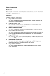
...Chapter 3: Installation Options This chapter describes how to perform when installing or removing system components. 3. This chapter includes the motherboard layout, jumper settings, and connector locations. 5. Detailed descriptions of configuring a server. Contents This guide contains the following ...This chapter tells how to change system settings through the BIOS Setup menus. viii Chapter 4: Motherboard Information This chapter gives information about the motherboard that you have to install optional components into the barebone server. 4. Chapter 1: Product Introduction...
...Chapter 3: Installation Options This chapter describes how to perform when installing or removing system components. 3. This chapter includes the motherboard layout, jumper settings, and connector locations. 5. Detailed descriptions of configuring a server. Contents This guide contains the following ...This chapter tells how to change system settings through the BIOS Setup menus. viii Chapter 4: Motherboard Information This chapter gives information about the motherboard that you have to install optional components into the barebone server. 4. Chapter 1: Product Introduction...

Series User Manual
Page 12
... following items. ESC4000 G4 / G4X / G4S Chassis ASUS 2U Rackmount Chassis Motherboard ASUS Z11PG-D16 Series Server Board Accessory box 1 x MB Support DVD 1 x ACC instruction card 1 x ASMB9 instruction card 1 x Bag of Screws 2 x Front PIKE II cables 2 x AC Power Cables 8 x 6+2 pin VGA Power cables 4 x ASUS CPU 8-pin ... x PIKE II RAID Card Optional Items 1 x Trend Micro Server Protect Anti-virus Software CD 1 x Redundant Power Supply Module • ASUS System Web-based Management If any of the above items is damaged or missing, contact your retailer. 1-2 Chapter 1: Product Introduction
... following items. ESC4000 G4 / G4X / G4S Chassis ASUS 2U Rackmount Chassis Motherboard ASUS Z11PG-D16 Series Server Board Accessory box 1 x MB Support DVD 1 x ACC instruction card 1 x ASMB9 instruction card 1 x Bag of Screws 2 x Front PIKE II cables 2 x AC Power Cables 8 x 6+2 pin VGA Power cables 4 x ASUS CPU 8-pin ... x PIKE II RAID Card Optional Items 1 x Trend Micro Server Protect Anti-virus Software CD 1 x Redundant Power Supply Module • ASUS System Web-based Management If any of the above items is damaged or missing, contact your retailer. 1-2 Chapter 1: Product Introduction

Series User Manual
Page 19
The middle part includes the I /O ports do not appear on the rear panel if motherboard is not present. • *The DM_LAN1 port is located on the 2 1 motherboard. ESC4000 G4 / G4X / G4S Half-length / Low-profile expansion slot VGA port USB 3.0 ports LAN port 2 LAN port 1 ...DM_LAN1* 4 Full-length Expansion slots Power cord connector and Redundant power supply 4 Full-length Expansion slots • The rear I /O shield with openings for ASUS ASMB9-iKVM ...
The middle part includes the I /O ports do not appear on the rear panel if motherboard is not present. • *The DM_LAN1 port is located on the 2 1 motherboard. ESC4000 G4 / G4X / G4S Half-length / Low-profile expansion slot VGA port USB 3.0 ports LAN port 2 LAN port 1 ...DM_LAN1* 4 Full-length Expansion slots Power cord connector and Redundant power supply 4 Full-length Expansion slots • The rear I /O shield with openings for ASUS ASMB9-iKVM ...

Series User Manual
Page 32
Lift the air duct to remove it from the motherboard. 2 1 2 1 2 1 2-4 Chapter 2: Hardware Setup Remove the three screws as shown below. 2. To remove the air duct: 1. The system layout may vary with models, but the installation steps are for all models. 2.1.1 Air duct The diagrams in this section are the same for reference only. Lift the CPU air duct to remove it from the chassis. 2 1 3.
Lift the air duct to remove it from the motherboard. 2 1 2 1 2 1 2-4 Chapter 2: Hardware Setup Remove the three screws as shown below. 2. To remove the air duct: 1. The system layout may vary with models, but the installation steps are for all models. 2.1.1 Air duct The diagrams in this section are the same for reference only. Lift the CPU air duct to remove it from the chassis. 2 1 3.

Series User Manual
Page 33
Align and replace the CPU air duct to the chassis ensuring that the screw holes on the air duct match the screw holes on chassis. 3. 2 1 To reinstall the air duct: 1. Align and replace the air duct to the motherboard. 2. Secure the air duct to the chassis with three screws removed earlier. 2 1 2 1 ASUS ESC4000 G4 Series 2-5
Align and replace the CPU air duct to the chassis ensuring that the screw holes on the air duct match the screw holes on chassis. 3. 2 1 To reinstall the air duct: 1. Align and replace the air duct to the motherboard. 2. Secure the air duct to the chassis with three screws removed earlier. 2 1 2 1 ASUS ESC4000 G4 Series 2-5

Series User Manual
Page 34
...removal of repair only if the damage is missing, or if you see the section Chassis cover. 2. ASUS will process Return Merchandise Authorization (RMA) requests only if the motherboard comes with the PnP cap on the LGA 3647 socket. • The product warranty does not cover ...damage to the PnP cap/socket contacts/motherboard components. ASUS will shoulder the cost of the PnP cap. 2.2.1 Installing the CPU and heatsink To install a CPU: 1. 2.2 Central Processing Unit (CPU) The motherboard comes with the cap on the LGA 3647 socket. 2-6 2 Chapter 2:...
...removal of repair only if the damage is missing, or if you see the section Chassis cover. 2. ASUS will process Return Merchandise Authorization (RMA) requests only if the motherboard comes with the PnP cap on the LGA 3647 socket. • The product warranty does not cover ...damage to the PnP cap/socket contacts/motherboard components. ASUS will shoulder the cost of the PnP cap. 2.2.1 Installing the CPU and heatsink To install a CPU: 1. 2.2 Central Processing Unit (CPU) The motherboard comes with the cap on the LGA 3647 socket. 2-6 2 Chapter 2:...

Series User Manual
Page 36
Reinstall the air duct. The heatsink screws are attached, tighten them one by one in a diagonal sequence to the motherboard. A torque value of the four screws with a screwdriver just enough to attach the heatsink to completely secure the heatsink. When the four screws are T30 models. For more information, see the section Air Duct. 1 34 2 2-8 Chapter 2: Hardware Setup 6. Twist each of 12 inch-lbf is recommended. 2 1 7.
Reinstall the air duct. The heatsink screws are attached, tighten them one by one in a diagonal sequence to the motherboard. A torque value of the four screws with a screwdriver just enough to attach the heatsink to completely secure the heatsink. When the four screws are T30 models. For more information, see the section Air Duct. 1 34 2 2-8 Chapter 2: Hardware Setup 6. Twist each of 12 inch-lbf is recommended. 2 1 7.

Series User Manual
Page 37
... 4 (DDR4) Dual Inline Memory Modules (DIMM) sockets. For optimum compatibility, it is recommended that you obtain memory modules from the same vendor. ASUS ESC4000 G4 Series 2-9 The figure illustrates the location of compatible DIMMs. • When installing only one DIMM in this section. • Refer to... ASUS Server AVL for the updated list of the DDR4 DIMM sockets: 2.3.2 Memory Configurations You may install 4GB, 8GB, 12GB, and 32GB RDIMMs;...
... 4 (DDR4) Dual Inline Memory Modules (DIMM) sockets. For optimum compatibility, it is recommended that you obtain memory modules from the same vendor. ASUS ESC4000 G4 Series 2-9 The figure illustrates the location of compatible DIMMs. • When installing only one DIMM in this section. • Refer to... ASUS Server AVL for the updated list of the DDR4 DIMM sockets: 2.3.2 Memory Configurations You may install 4GB, 8GB, 12GB, and 32GB RDIMMs;...

Series User Manual
Page 43
... the DIMM. 3. Remove the DIMM from a single clip DIMM socket 1. ASUS ESC4000 G4 Series 2-15 DO NOT force a DIMM into the socket. Support the DIMM lightly with extra force. Apply force to both ends, then insert the DIMM vertically into a socket in the motherboard package. • Refer to ensure proper sitting of the memory... into place, and the DIMM cannot be pushed in only one direction. The DIMM might get damaged when it fits in any further to www.asus.com for vendor lists of the DIMM.
... the DIMM. 3. Remove the DIMM from a single clip DIMM socket 1. ASUS ESC4000 G4 Series 2-15 DO NOT force a DIMM into the socket. Support the DIMM lightly with extra force. Apply force to both ends, then insert the DIMM vertically into a socket in the motherboard package. • Refer to ensure proper sitting of the memory... into place, and the DIMM cannot be pushed in only one direction. The DIMM might get damaged when it fits in any further to www.asus.com for vendor lists of the DIMM.

Series User Manual
Page 44
...the SATA/SAS interface on the drive connects to the motherboard SATA/SAS ports via the SATA/SAS backplane. 2.4.1 Installing the 3.5-inch SATA/SAS storage device ESC4000 G4 1. Repeat steps 1 to 5 to remove the drive tray. 3. 2.4 Storage devices The ESC4000 G4 series supports 3.5-inch and 2.5-inch SATA/SAS storage ...Push the drive tray and storage device assembly all the way into the tray then secure it with the bay edge. 6. For the ESC4000 G4 system, the storage device installed in place. • When installed, the SATA/SAS connector on the backplane. • The drive tray...
...the SATA/SAS interface on the drive connects to the motherboard SATA/SAS ports via the SATA/SAS backplane. 2.4.1 Installing the 3.5-inch SATA/SAS storage device ESC4000 G4 1. Repeat steps 1 to 5 to remove the drive tray. 3. 2.4 Storage devices The ESC4000 G4 series supports 3.5-inch and 2.5-inch SATA/SAS storage ...Push the drive tray and storage device assembly all the way into the tray then secure it with the bay edge. 6. For the ESC4000 G4 system, the storage device installed in place. • When installed, the SATA/SAS connector on the backplane. • The drive tray...

Series User Manual
Page 51
...that supports one x16 slot (x8 Gen3 link) for installing PCI-E x16 low profile cards and one x8 slot (x8 Gen3 link) for installing ASUS PCI-E x8 low profile cards. 2.5 Expansion slots Ensure to the riser card: 1. PCI-E x16 slot low-profile PCI-E x8 slot low-profile...Express x24 slot on the motherboard comes pre-installed with a riser card that secure the riser card to do so may cause you physical injury and damage motherboard components. 2.5.1 The PCI Express riser card The onboard PCI Express slot on the motherboard. Failure to the chassis. 2. ASUS ESC4000 G4 Series 2-23
...that supports one x16 slot (x8 Gen3 link) for installing PCI-E x16 low profile cards and one x8 slot (x8 Gen3 link) for installing ASUS PCI-E x8 low profile cards. 2.5 Expansion slots Ensure to the riser card: 1. PCI-E x16 slot low-profile PCI-E x8 slot low-profile...Express x24 slot on the motherboard comes pre-installed with a riser card that secure the riser card to do so may cause you physical injury and damage motherboard components. 2.5.1 The PCI Express riser card The onboard PCI Express slot on the motherboard. Failure to the chassis. 2. ASUS ESC4000 G4 Series 2-23

Series User Manual
Page 53
PCI-E slot riser card and expansion card assembly ASUS ESC4000 G4 Series 2-25 Secure the riser card with the two (2) screws that you removed earlier in one orientation only. The expansion card fits in step 1. If it does not fit, try reversing it. 8. 7. Align and insert the riser card and expansion card assembly into the PCI-E slot on the motherboard.
PCI-E slot riser card and expansion card assembly ASUS ESC4000 G4 Series 2-25 Secure the riser card with the two (2) screws that you removed earlier in one orientation only. The expansion card fits in step 1. If it does not fit, try reversing it. 8. 7. Align and insert the riser card and expansion card assembly into the PCI-E slot on the motherboard.
Series User Manual
Page 54
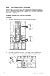
... the system. Remove the screw from the motherboard and the backplane. 2. Remove the default cable from the bracket (A), then push the internal SAS/HBA/Storage bracket towards the rear to the front of the system: ESC4000 G4 1. 2.5.2 Installing an ASUS PIKE II card You may install an ASUS PIKE II card to the internal SAS...
... the system. Remove the screw from the motherboard and the backplane. 2. Remove the default cable from the bracket (A), then push the internal SAS/HBA/Storage bracket towards the rear to the front of the system: ESC4000 G4 1. 2.5.2 Installing an ASUS PIKE II card You may install an ASUS PIKE II card to the internal SAS...

Series User Manual
Page 61
ASUS ESC4000 G4 Series 2-33 ESC4000 G4S 1. Release the four (4) thumbscrews on the Cache Vault Power Module clip holder. Remove the default cable from the motherboard and the backplane. 2.
ASUS ESC4000 G4 Series 2-33 ESC4000 G4S 1. Release the four (4) thumbscrews on the Cache Vault Power Module clip holder. Remove the default cable from the motherboard and the backplane. 2.

Series User Manual
Page 67
Install the ASUS PIKE II card to ASUS PIKE II connector 1 3. ASUS ESC4000 G4 Series 2-39 connect to ASUS PIKE II connector 2 connect to the riser card. Remove the default cable from the motherboard and the backplane. 2. Refer to section 2.5.1 The PCI Express riser card for the steps on installing an expansion card to the ASUS PIKE II card. Ensure that the metal cover is inserted and firmly seated in place. Connect the two mini SAS HD cables to the riser card. To install an ASUS PIKE II card to the rear of the system: 1.
Install the ASUS PIKE II card to ASUS PIKE II connector 1 3. ASUS ESC4000 G4 Series 2-39 connect to ASUS PIKE II connector 2 connect to the riser card. Remove the default cable from the motherboard and the backplane. 2. Refer to section 2.5.1 The PCI Express riser card for the steps on installing an expansion card to the ASUS PIKE II card. Ensure that the metal cover is inserted and firmly seated in place. Connect the two mini SAS HD cables to the riser card. To install an ASUS PIKE II card to the rear of the system: 1.

Series User Manual
Page 69
... devices. • Refer to SATA backplane board) ASUS ESC4000 G4 Series 2-41 Pre-connected system cables 1. 20-pin SSI power connector (from the power distribution board to the motherboard) 2. 8-pin SSI power connector (from motherboard to front I /O board) 7. ISATA connectors (from motherboard to front I /O board) 6. Auxiliary Panel connectors (from motherboard to Chapter 4 for detailed information on the...
... devices. • Refer to SATA backplane board) ASUS ESC4000 G4 Series 2-41 Pre-connected system cables 1. 20-pin SSI power connector (from the power distribution board to the motherboard) 2. 8-pin SSI power connector (from motherboard to front I /O board) 7. ISATA connectors (from motherboard to front I /O board) 6. Auxiliary Panel connectors (from motherboard to Chapter 4 for detailed information on the...

Series User Manual
Page 70
... FRNT_FAN5 connects to the system fans * Ensure to connect the corresponding 8-pin plugs to mini-SAS HD connectors 1 and 2 on the motherboard or ASUS PIKE II connectors. 2.7 SATA/SAS backplane cabling ESC4000 G4 connects 8-pin plugs from power supply* connect to PWR1 and PWR2 as shown below: PWR1 PWR2 red yellow black black yellow...
... FRNT_FAN5 connects to the system fans * Ensure to connect the corresponding 8-pin plugs to mini-SAS HD connectors 1 and 2 on the motherboard or ASUS PIKE II connectors. 2.7 SATA/SAS backplane cabling ESC4000 G4 connects 8-pin plugs from power supply* connect to PWR1 and PWR2 as shown below: PWR1 PWR2 red yellow black black yellow...

Series User Manual
Page 71
ESC4000 G4S connects 8-pin plugs from power supply* connect to mini-SAS HD connectors 1 and 2 on the motherboard or ASUS PIKE II connectors. With two mini-SAS HD cables connected, a total number of 8 SAS/SATA storage devices can be supported MB_RST1 ® MSAS_HD1 BP8LX4LE12G-25-R23A SMBUS1 BPSMB1 PWR1 OCUPCIE8 OCUPCIE7 MSAS_HD2 ASUS ESC4000 G4 Series 2-43
ESC4000 G4S connects 8-pin plugs from power supply* connect to mini-SAS HD connectors 1 and 2 on the motherboard or ASUS PIKE II connectors. With two mini-SAS HD cables connected, a total number of 8 SAS/SATA storage devices can be supported MB_RST1 ® MSAS_HD1 BP8LX4LE12G-25-R23A SMBUS1 BPSMB1 PWR1 OCUPCIE8 OCUPCIE7 MSAS_HD2 ASUS ESC4000 G4 Series 2-43

Series User Manual
Page 79
... the thumbscrew in the accessory box. 2 1 mylar GPU air duct mylar ASUS ESC4000 G4 Series 2-51 For AMD S9150 or later GPU cards, attach a mylar to the GPU air duct first before installing the air duct to detach it from the motherboard then set it aside. 4. The mylar is bundled with the system and...
... the thumbscrew in the accessory box. 2 1 mylar GPU air duct mylar ASUS ESC4000 G4 Series 2-51 For AMD S9150 or later GPU cards, attach a mylar to the GPU air duct first before installing the air duct to detach it from the motherboard then set it aside. 4. The mylar is bundled with the system and...

