User Guide
Page 4
... 3-1 3.1.2 ASUS EZ Flash 2 utility 3-4 3.1.3 ASUS CrashFree BIOS 3 utility 3-5 3.2 BIOS setup program 3-6 3.2.1 BIOS menu screen 3-7 3.2.2 Menu bar 3-7 3.2.3 Navigation keys 3-7 3.2.4 Menu items 3-8 3.2.5 Submenu items 3-8 3.2.6 Configuration fields 3-8 3.2.7 Pop-up window 3-8 3.2.8 Scroll bar 3-8 3.2.9 General help 3-8 3.3 Extreme Tweaker menu 3-9 3.3.1 CPU Level Up 3-9 3.3.2 OC Tuner Utility 3-10 3.3.3 Ai Overclock Tuner 3-10 3.3.4 CPU Ratio 3-11 3.3.5 DRAM Frequency 3-11 3.3.6 CPU/NB Frequency 3-11 iv
... 3-1 3.1.2 ASUS EZ Flash 2 utility 3-4 3.1.3 ASUS CrashFree BIOS 3 utility 3-5 3.2 BIOS setup program 3-6 3.2.1 BIOS menu screen 3-7 3.2.2 Menu bar 3-7 3.2.3 Navigation keys 3-7 3.2.4 Menu items 3-8 3.2.5 Submenu items 3-8 3.2.6 Configuration fields 3-8 3.2.7 Pop-up window 3-8 3.2.8 Scroll bar 3-8 3.2.9 General help 3-8 3.3 Extreme Tweaker menu 3-9 3.3.1 CPU Level Up 3-9 3.3.2 OC Tuner Utility 3-10 3.3.3 Ai Overclock Tuner 3-10 3.3.4 CPU Ratio 3-11 3.3.5 DRAM Frequency 3-11 3.3.6 CPU/NB Frequency 3-11 iv
User Guide
Page 7
4.3.8 ASUS Unique Overclocking Utility-TurboV EVO......... 4-23 4.3.9 ROG Connect 4-26 4.4 RAID configurations 4-28 4.4.1 RAID definitions 4-28 4.4.2 Installing Serial ATA hard disks 4-29 4.4.3 Setting the RAID item in BIOS 4-29 4.4.4 AMD® Option ROM Utility 4-30 4.5 Creating a RAID driver disk 4-33 4.5.1 Creating a RAID driver disk without entering the OS.... 4-33 4.5.2 Creating a RAID driver disk...
4.3.8 ASUS Unique Overclocking Utility-TurboV EVO......... 4-23 4.3.9 ROG Connect 4-26 4.4 RAID configurations 4-28 4.4.1 RAID definitions 4-28 4.4.2 Installing Serial ATA hard disks 4-29 4.4.3 Setting the RAID item in BIOS 4-29 4.4.4 AMD® Option ROM Utility 4-30 4.5 Creating a RAID driver disk 4-33 4.5.1 Creating a RAID driver disk without entering the OS.... 4-33 4.5.2 Creating a RAID driver disk...
User Guide
Page 10
... additional information and for the LCD Poster. Detailed descriptions of the BIOS parameters are not part of the switches, jumpers, and connectors on ASUS hardware and software products. Refer to change system settings through the BIOS Setup menus. Optional documentation Your product package may have to install ...product and software updates. 1. How this guide This user guide contains the information you have been added by your dealer. ASUS websites The ASUS website provides updated information on the motherboard. • Chapter 3: BIOS setup This chapter tells how to the...
... additional information and for the LCD Poster. Detailed descriptions of the BIOS parameters are not part of the switches, jumpers, and connectors on ASUS hardware and software products. Refer to change system settings through the BIOS Setup menus. Optional documentation Your product package may have to install ...product and software updates. 1. How this guide This user guide contains the information you have been added by your dealer. ASUS websites The ASUS website provides updated information on the motherboard. • Chapter 3: BIOS setup This chapter tells how to the...
User Guide
Page 13
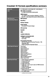
Voltiminder LED - COP EX (Component Overheat Protection - ASUS C.P.R.(CPU Parameter Recall) Turbo Key II Core Unlocker ASUS Q-Connector ASUS Q-Shield ASUS Q-Fan 2 ASUS EZ Flash 2 ASUS CrashFree BIOS 3 ASUS MyLogo 3 AMD® OverDrive Support* ASUS TurboV EVO 1 x PS/2 Keyboard port(purple) 1 x External SATA port 1 ...power design CPU Level Up MemOK! O.C Profile Overclocking Protection - ASUS TurboV EVO - EX) - iROG Loadline Calibration Intelligent overclocking tools - Crosshair IV Formula specifications summary IEEE 1394 USB ROG Exclusive Overclocking Features Other Special ...
Voltiminder LED - COP EX (Component Overheat Protection - ASUS C.P.R.(CPU Parameter Recall) Turbo Key II Core Unlocker ASUS Q-Connector ASUS Q-Shield ASUS Q-Fan 2 ASUS EZ Flash 2 ASUS CrashFree BIOS 3 ASUS MyLogo 3 AMD® OverDrive Support* ASUS TurboV EVO 1 x PS/2 Keyboard port(purple) 1 x External SATA port 1 ...power design CPU Level Up MemOK! O.C Profile Overclocking Protection - ASUS TurboV EVO - EX) - iROG Loadline Calibration Intelligent overclocking tools - Crosshair IV Formula specifications summary IEEE 1394 USB ROG Exclusive Overclocking Features Other Special ...
User Guide
Page 14
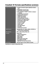
... applications * ASUS PC Probe II * ASUS Update * ASUS AI Suite * AMD OverDrive Utility (AOD) * Sound Blaster X-Fi Utility * Kaspersky® Anti-Virus (1-year license) ATX Form Factor, 12"x 9.6" (30.5cm x 24.5cm) *Specifications are subject to change without notice. Crosshair IV Formula specifications summary Internal I/O Connectors BIOS Features Manageability ...key II switch 1 x Power on switch 1 x Reset switch 1 x OC Station Header 1 x Go Button 1 x System panel connector 16Mb AMI BIOS, PnP, DMI2.0, WfM2.0, SM BIOS 2.4, ACPI2.0a Multi-Language BIOS WOL by PME, WOR by PME, PXE Support DVD: -
... applications * ASUS PC Probe II * ASUS Update * ASUS AI Suite * AMD OverDrive Utility (AOD) * Sound Blaster X-Fi Utility * Kaspersky® Anti-Virus (1-year license) ATX Form Factor, 12"x 9.6" (30.5cm x 24.5cm) *Specifications are subject to change without notice. Crosshair IV Formula specifications summary Internal I/O Connectors BIOS Features Manageability ...key II switch 1 x Power on switch 1 x Reset switch 1 x OC Station Header 1 x Go Button 1 x System panel connector 16Mb AMI BIOS, PnP, DMI2.0, WfM2.0, SM BIOS 2.4, ACPI2.0a Multi-Language BIOS WOL by PME, WOR by PME, PXE Support DVD: -
User Guide
Page 22
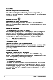
...offers premium antivirus protection for malicious program detection rates that are among the industry's highest. 1.3.4 ASUS special features ASUS Turbo Key II Switch on the Potential, Turn up the Performance Enjoy superb performance by simply ...while TurboV offers more shorting pins or moving jumpers. It is renowned for individual users and home offices. ASUS TurboV EVO The ultimate O.C. Simply activate a dedicated switch on advanced antivirus technologies. Turbo Key boosts performance with...to effortlessly fine-tune the performance without performing complicating BIOS changes.
...offers premium antivirus protection for malicious program detection rates that are among the industry's highest. 1.3.4 ASUS special features ASUS Turbo Key II Switch on the Potential, Turn up the Performance Enjoy superb performance by simply ...while TurboV offers more shorting pins or moving jumpers. It is renowned for individual users and home offices. ASUS TurboV EVO The ultimate O.C. Simply activate a dedicated switch on advanced antivirus technologies. Turbo Key boosts performance with...to effortlessly fine-tune the performance without performing complicating BIOS changes.
User Guide
Page 23
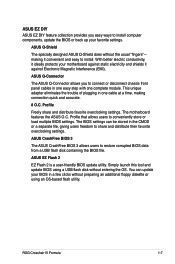
... using a USB flash disk without the usual "fingers"- The BIOS settings can update your motherboard against Electronic Magnetic Interference (EMI). ASUS EZ Flash 2 EZ Flash 2 is a user-friendly BIOS update utility. ASUS EZ DIY ASUS EZ DIY feature collection provides you to connect or disconnect chassis..., making it against static electricity and shields it convenient and easy to conveniently store or load multiple BIOS settings. ASUS CrashFree BIOS 3 The ASUS CrashFree BIOS 3 allows users to share and distribute their favorite overclocking settings. ROG Crosshair IV Formula 1-7
... using a USB flash disk without the usual "fingers"- The BIOS settings can update your motherboard against Electronic Magnetic Interference (EMI). ASUS EZ Flash 2 EZ Flash 2 is a user-friendly BIOS update utility. ASUS EZ DIY ASUS EZ DIY feature collection provides you to connect or disconnect chassis..., making it against static electricity and shields it convenient and easy to conveniently store or load multiple BIOS settings. ASUS CrashFree BIOS 3 The ASUS CrashFree BIOS 3 allows users to share and distribute their favorite overclocking settings. ROG Crosshair IV Formula 1-7
User Guide
Page 28
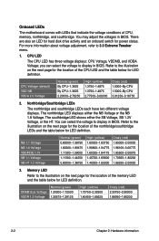
For more information about voltage adjustment, refer to display in BIOS. CPU LED The CPU LED has three voltage displays: CPU Voltage, VDDNB, and VDDA Voltage; Refer to the illustration on the next page for the ...-1.39125 High (yellow) 1.73750-2.32500 1.40450-1.65625 Crazy (red) 2.33750-2.90000 1.66950-1.80200 2-2 Chapter 2: Hardware information Memory LED Refer to display in BIOS. You may adjust the voltages in BIOS. you can select the voltage to the illustration on the next page for the location of the CPU LED and the table...
For more information about voltage adjustment, refer to display in BIOS. CPU LED The CPU LED has three voltage displays: CPU Voltage, VDDNB, and VDDA Voltage; Refer to the illustration on the next page for the ...-1.39125 High (yellow) 1.73750-2.32500 1.40450-1.65625 Crazy (red) 2.33750-2.90000 1.66950-1.80200 2-2 Chapter 2: Hardware information Memory LED Refer to display in BIOS. You may adjust the voltages in BIOS. you can select the voltage to the illustration on the next page for the location of the CPU LED and the table...
User Guide
Page 49
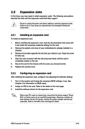
...necessary hardware settings for the card. 2. Turn on BIOS setup. 2. Assign an IRQ to unplug the power cord before adding or removing expansion cards. When using PCI cards on the slot. 5. Ensure to the card. ROG Crosshair IV Formula 2-23 Keep the screw for details. Install the ...software drivers for information on the system and change the necessary BIOS settings, if any. Remove the bracket opposite the slot that the cards do...
...necessary hardware settings for the card. 2. Turn on BIOS setup. 2. Assign an IRQ to unplug the power cord before adding or removing expansion cards. When using PCI cards on the slot. 5. Ensure to the card. ROG Crosshair IV Formula 2-23 Keep the screw for details. Install the ...software drivers for information on the system and change the necessary BIOS settings, if any. Remove the bracket opposite the slot that the cards do...
User Guide
Page 52
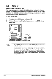
... when the system hangs due to CPU overclocking. The clr CMOS switch on the back I /O. 2. Hold down the key during the boot process and enter BIOS setup to re-enter data. • The clr CMOS switch will not function if the CLRTC_SW jumper is moved to the Disable position. • Ensure... RTC RAM: 1. With the C.P.R. (CPU Parameter Recall) feature, shut down the clr CMOS switch on the back I /O. Press down and reboot the system so the BIOS can clear the CMOS memory and system setup parameters by erasing the CMOS RTC RAM data. You can automatically reset CPU parameter settings to re...
... when the system hangs due to CPU overclocking. The clr CMOS switch on the back I /O. 2. Hold down the key during the boot process and enter BIOS setup to re-enter data. • The clr CMOS switch will not function if the CLRTC_SW jumper is moved to the Disable position. • Ensure... RTC RAM: 1. With the C.P.R. (CPU Parameter Recall) feature, shut down the clr CMOS switch on the back I /O. Press down and reboot the system so the BIOS can clear the CMOS memory and system setup parameters by erasing the CMOS RTC RAM data. You can automatically reset CPU parameter settings to re...
User Guide
Page 54
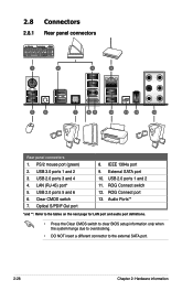
... Ports** *and **: Refer to the tables on the next page for LAN port and audio port definitions. • Press the Clear CMOS switch to clear BIOS setup information only when the system hangs due to overclocking. • DO NOT insert a different connector to the external SATA port. 2-28 Chapter 2: Hardware information...
... Ports** *and **: Refer to the tables on the next page for LAN port and audio port definitions. • Press the Clear CMOS switch to clear BIOS setup information only when the system hangs due to overclocking. • DO NOT insert a different connector to the external SATA port. 2-28 Chapter 2: Hardware information...
User Guide
Page 58
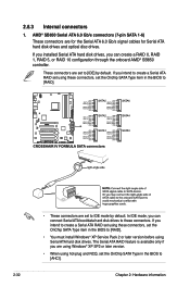
... or later version. • When using hot-plug and NCQ, set to [IDE] by default. These connectors are set the OnChip SATA Type in the BIOS to [AHCI]. 2-32 Chapter 2: Hardware information If you intend to these connectors, set to IDE mode by default. If you intend to create a Serial ...ATA RAID set using these connectors, set the OnChip SATA Type item in the BIOS to [RAID]. • These connectors are set the Onchip SATA Type item in the BIOS to [RAID]. • You must install Windows® XP Service Pack 2 or later version before using these ...
... or later version. • When using hot-plug and NCQ, set to [IDE] by default. These connectors are set the OnChip SATA Type in the BIOS to [AHCI]. 2-32 Chapter 2: Hardware information If you intend to these connectors, set to IDE mode by default. If you intend to create a Serial ...ATA RAID set using these connectors, set the OnChip SATA Type item in the BIOS to [RAID]. • These connectors are set the Onchip SATA Type item in the BIOS to [RAID]. • You must install Windows® XP Service Pack 2 or later version before using these ...
User Guide
Page 60
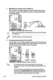
... audio capability. • If you want to connect a high-definition front panel audio module to this connector, set the Front Panel Type item in the BIOS setup to [HD]; IEEE 1394a port connector (10-1 pin IE1394_2) This connector is purchased separately. 5.
... audio capability. • If you want to connect a high-definition front panel audio module to this connector, set the Front Panel Type item in the BIOS setup to [HD]; IEEE 1394a port connector (10-1 pin IE1394_2) This connector is purchased separately. 5.
User Guide
Page 62
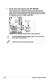
The optional fan1/2/3 can work with the temperature sensors for temperature monitoring. The thermal sensor cable is purchased separately. 2-36 Chapter 2: Hardware information 7. Enable OPT FAN1/2/3 overheat protection in BIOS if you want to these connectors. Thermal sensor cable connectors (2-pin OPT_TEMP1/2/3) These connectors are for a better cooling effect. Connect the thermal sensor cables to these connectors and place the other ends to the devices which you connect thermal sensor cables to monitor temperature.
The optional fan1/2/3 can work with the temperature sensors for temperature monitoring. The thermal sensor cable is purchased separately. 2-36 Chapter 2: Hardware information 7. Enable OPT FAN1/2/3 overheat protection in BIOS if you want to these connectors. Thermal sensor cable connectors (2-pin OPT_TEMP1/2/3) These connectors are for a better cooling effect. Connect the thermal sensor cables to these connectors and place the other ends to the devices which you connect thermal sensor cables to monitor temperature.
User Guide
Page 65
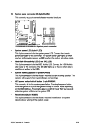
... system is in sleep mode. • Hard disk drive activity LED (2-pin IDE_LED) This 2-pin connector is for the chassis-mounted system warning speaker. ROG Crosshair IV Formula 2-39 System panel connector (20-8 pin PANEL) This connector supports several chassis-mounted functions. • System power LED (2-pin PLED) This 2-pin connector is for... turns the system OFF. • Reset button (2-pin RESET) This 2-pin connector is for the system power LED. The speaker allows you turn on the BIOS settings. 11.
... system is in sleep mode. • Hard disk drive activity LED (2-pin IDE_LED) This 2-pin connector is for the chassis-mounted system warning speaker. ROG Crosshair IV Formula 2-39 System panel connector (20-8 pin PANEL) This connector supports several chassis-mounted functions. • System power LED (2-pin PLED) This 2-pin connector is for... turns the system OFF. • Reset button (2-pin RESET) This 2-pin connector is for the system power LED. The speaker allows you turn on the BIOS settings. 11.
User Guide
Page 69
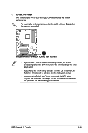
...the last setting you have made. ROG Crosshair IV Formula 2-43 For ensuring the system performance, turn the switch setting to Enable when the system is powered off. • If you clear the CMOS or load the BIOS setup defaults, the related overclocking items in the BIOS menu follow the current setting of the Turbo...to auto-tune your CPU to Enable under the OS environment, the Turbo Key II function will use the TurboV Auto Tuning, overclock in the BIOS setup program, and enable the Turbo Key II function at the same time. Turbo Key II switch This switch allows you change the switch ...
...the last setting you have made. ROG Crosshair IV Formula 2-43 For ensuring the system performance, turn the switch setting to Enable when the system is powered off. • If you clear the CMOS or load the BIOS setup defaults, the related overclocking items in the BIOS menu follow the current setting of the Turbo...to auto-tune your CPU to Enable under the OS environment, the Turbo Key II function will use the TurboV Auto Tuning, overclock in the BIOS setup program, and enable the Turbo Key II function at the same time. Turbo Key II switch This switch allows you change the switch ...
User Guide
Page 70
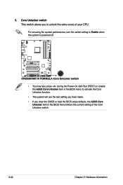
... function. • The system will use the last setting you have made. • If you clear the CMOS or load the BIOS setup defaults, the ASUS Core Unlocker item in the BIOS menu follows the current setting of your CPU. For ensuring the system performance, turn the switch setting to Enable when the... system is powered off. • You may also press during the Power-On-Self-Test (POST) or enable the ASUS Core Unlocker item in the BIOS menu to unlock the extra cores of the Core Unlocker switch. 2-44 Chapter 2: Hardware information
... function. • The system will use the last setting you have made. • If you clear the CMOS or load the BIOS setup defaults, the ASUS Core Unlocker item in the BIOS menu follows the current setting of your CPU. For ensuring the system performance, turn the switch setting to Enable when the... system is powered off. • You may also press during the Power-On-Self-Test (POST) or enable the ASUS Core Unlocker item in the BIOS menu to unlock the extra cores of the Core Unlocker switch. 2-44 Chapter 2: Hardware information
User Guide
Page 72
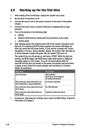
... on test. If your retailer for the first time 1. Follow the instructions in the following order: a. Connect the power cord to enter the BIOS Setup. While the tests are off. 3. Connect the power cord to disabled No keyboard detected One continuous beep followed by two short beeps then ...the power, the system may have failed a power-on the devices in Chapter 3. 2-46 Chapter 2: Hardware information If you do not see BIOS beep codes table below) or additional messages appear on the system front panel case lights up for assistance. External SCSI devices (starting with a ...
... on test. If your retailer for the first time 1. Follow the instructions in the following order: a. Connect the power cord to enter the BIOS Setup. While the tests are off. 3. Connect the power cord to disabled No keyboard detected One continuous beep followed by two short beeps then ...the power, the system may have failed a power-on the devices in Chapter 3. 2-46 Chapter 2: Hardware information If you do not see BIOS beep codes table below) or additional messages appear on the system front panel case lights up for assistance. External SCSI devices (starting with a ...
User Guide
Page 73
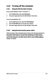
...Windows® XP: 1. Refer to soft-off mode, depending on the BIOS setting. If you are using Windows® Vista™ / Windows® 7™: 1. Pressing the power switch for details. ROG Crosshair IV Formula 2-47 2.10 Turning off the computer 2.10.1 Using the OS shut down... the computer. 3. The power supply should turn off mode regardless of the BIOS setting. The power supply should turn off after Windows® shuts...
...Windows® XP: 1. Refer to soft-off mode, depending on the BIOS setting. If you are using Windows® Vista™ / Windows® 7™: 1. Pressing the power switch for details. ROG Crosshair IV Formula 2-47 2.10 Turning off the computer 2.10.1 Using the OS shut down... the computer. 3. The power supply should turn off mode regardless of the BIOS setting. The power supply should turn off after Windows® shuts...
User Guide
Page 75
Detailed descriptions of the BIOS parameters are also provided. This chapter tells how to change the BIOS se3tup system settings through the BIOS Setup menus.
Detailed descriptions of the BIOS parameters are also provided. This chapter tells how to change the BIOS se3tup system settings through the BIOS Setup menus.


