

User Guide
Page 1
B85M-D PLUS Motherboard
B85M-D PLUS Motherboard
User Guide
Page 3
Contents Safety information...iv About this guide...iv Package contents...vi B85M-D PLUS specifications summary vi Chapter 1: Product introduction 1.1 Before you proceed 1-1 1.2 Motherboard overview 1-2 1.3 Central Processing Unit (CPU 1-4 1.4 System memory 1-8 1.5 Expansion slots 1-10 1.6 Headers...1-12 1.7 Connectors 1-13 1.9 Software support 1-21 Chapter 2: BIOS information 2.1... Tweaker menu 2-12 2.6 Advanced menu 2-20 2.7 Monitor menu 2-29 2.8 Boot menu 2-32 2.9 Tools menu 2-38 2.10 Exit menu...2-39 Appendices Notices...A-1 ASUS contact information A-3 iii
Contents Safety information...iv About this guide...iv Package contents...vi B85M-D PLUS specifications summary vi Chapter 1: Product introduction 1.1 Before you proceed 1-1 1.2 Motherboard overview 1-2 1.3 Central Processing Unit (CPU 1-4 1.4 System memory 1-8 1.5 Expansion slots 1-10 1.6 Headers...1-12 1.7 Connectors 1-13 1.9 Software support 1-21 Chapter 2: BIOS information 2.1... Tweaker menu 2-12 2.6 Advanced menu 2-20 2.7 Monitor menu 2-29 2.8 Boot menu 2-32 2.9 Tools menu 2-38 2.10 Exit menu...2-39 Appendices Notices...A-1 ASUS contact information A-3 iii
User Guide
Page 4
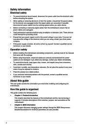
...About this guide is organized This guide contains the following parts: • Chapter 1: Product introduction This chapter describes the features of the motherboard and the new technology it may be exposed to or from the system, ensure that all cables are correctly connected and the power ... correct voltage in any damage, contact your retailer. If you add a device. • Before connecting or removing signal cables from the motherboard, ensure that the power cables for the BIOS parameters are using an adapter or extension cord. These devices could interrupt the grounding circuit. ...
...About this guide is organized This guide contains the following parts: • Chapter 1: Product introduction This chapter describes the features of the motherboard and the new technology it may be exposed to or from the system, ensure that all cables are correctly connected and the power ... correct voltage in any damage, contact your retailer. If you add a device. • Before connecting or removing signal cables from the motherboard, ensure that the power cables for the BIOS parameters are using an adapter or extension cord. These devices could interrupt the grounding circuit. ...

User Guide
Page 6
... at back panel) 8 x USB 2.0 ports (4 ports at midboard, 4 ports at back panel) (continued on the CPU types. ** Refer to www.asus.com for the following items. Motherboard Cables Accessories Application DVD Documentation ASUS B85M-D PLUS motherboard 2 x Serial ATA 6.0 Gb/s cables 1 x I/O Shield Support DVD User Guide If any of the above items is damaged or missing, contact...
... at back panel) 8 x USB 2.0 ports (4 ports at midboard, 4 ports at back panel) (continued on the CPU types. ** Refer to www.asus.com for the following items. Motherboard Cables Accessories Application DVD Documentation ASUS B85M-D PLUS motherboard 2 x Serial ATA 6.0 Gb/s cables 1 x I/O Shield Support DVD User Guide If any of the above items is damaged or missing, contact...

User Guide
Page 9
... the component. • Before you install motherboard components or change any motherboard settings. • Unplug the power cord from the power supply. Failure to do so may cause severe damage to avoid touching the ICs on them due to static electricity. • Hold components by the edges to the motherboard, peripherals, or components. ASUS B85M-D PLUS 1-1
... the component. • Before you install motherboard components or change any motherboard settings. • Unplug the power cord from the power supply. Failure to do so may cause severe damage to avoid touching the ICs on them due to static electricity. • Hold components by the edges to the motherboard, peripherals, or components. ASUS B85M-D PLUS 1-1

User Guide
Page 10
... image. 1.2.2 Screw holes Place six screws into the holes indicated by circles to secure the motherboard to ensure that the motherboard fits. Failure to do so can damage the motherboard. The edge with external ports goes to the rear part of your chassis to the chassis.... Do not overtighten the screws! Doing so can cause you install the motherboard, study the configuration of the chassis as indicated in the correct orientation. Place this side towards the rear of the chassis B85M-D PLUS 1-2 Chapter 1: Product introduction Unplug the power cord before installing or removing...
... image. 1.2.2 Screw holes Place six screws into the holes indicated by circles to secure the motherboard to ensure that the motherboard fits. Failure to do so can damage the motherboard. The edge with external ports goes to the rear part of your chassis to the chassis.... Do not overtighten the screws! Doing so can cause you install the motherboard, study the configuration of the chassis as indicated in the correct orientation. Place this side towards the rear of the chassis B85M-D PLUS 1-2 Chapter 1: Product introduction Unplug the power cord before installing or removing...

User Guide
Page 12
... 1-15 1-17 1-4 1-8 1-19 1-18 1-17 1-20 1-18 1-19 1-12 1-20 1-16 1-16 1-15 1.3 Central Processing Unit (CPU) This motherboard comes with a surface mount LGA1150 socket designed for the 4th Generation Intel® Core™ i7 / Core™ i5 / Core™ i3, Pentium... COM) 14. CPU and chassis fan connectors (4-pin CPU_FAN, 4-pin CHA_FAN) 3. ATX power connectors (24-pin EATXPWR, 4-pin ATX12V) 2. B85M-D PLUS B85M-D PLUS CPU socket LGA1150 Unplug all power cables before installing the CPU. 1-4 Chapter 1: Product introduction Intel® B85 Serial ATA 6.0Gb/s connectors (7-pin...
... 1-15 1-17 1-4 1-8 1-19 1-18 1-17 1-20 1-18 1-19 1-12 1-20 1-16 1-16 1-15 1.3 Central Processing Unit (CPU) This motherboard comes with a surface mount LGA1150 socket designed for the 4th Generation Intel® Core™ i7 / Core™ i5 / Core™ i3, Pentium... COM) 14. CPU and chassis fan connectors (4-pin CPU_FAN, 4-pin CHA_FAN) 3. ATX power connectors (24-pin EATXPWR, 4-pin ATX12V) 2. B85M-D PLUS B85M-D PLUS CPU socket LGA1150 Unplug all power cables before installing the CPU. 1-4 Chapter 1: Product introduction Intel® B85 Serial ATA 6.0Gb/s connectors (7-pin...
User Guide
Page 13
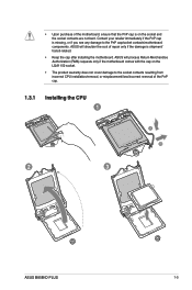
.... • The product warranty does not cover damage to the PnP cap/socket contacts/motherboard components. ASUS will shoulder the cost of the PnP cap. 1.3.1 Installing the CPU 1 A B 2 3 ASUS B85M-D PLUS 1-5 ASUS will process Return Merchandise Authorization (RMA) requests only if the motherboard comes with the cap on the socket and the socket contacts are not bent.
.... • The product warranty does not cover damage to the PnP cap/socket contacts/motherboard components. ASUS will shoulder the cost of the PnP cap. 1.3.1 Installing the CPU 1 A B 2 3 ASUS B85M-D PLUS 1-5 ASUS will process Return Merchandise Authorization (RMA) requests only if the motherboard comes with the cap on the socket and the socket contacts are not bent.

User Guide
Page 16
... the memory address limitation on a DDR2 DIMM socket. com/kb/929605/en-us. • This motherboard does not support DIMMs made up of the DDR3 DIMM sockets: DIMM_A1 DIMM_B1 Channel Sockets B85M-D PLUS Channel A DIMM_A1 Channel B DIMM_B1 B85M-D PLUS 240-pin DDR3 DIMM sockets 1.4.2 Memory configurations You may install 1GB, 2GB, 4GB, and 8GB unbuffered...
... the memory address limitation on a DDR2 DIMM socket. com/kb/929605/en-us. • This motherboard does not support DIMMs made up of the DDR3 DIMM sockets: DIMM_A1 DIMM_B1 Channel Sockets B85M-D PLUS Channel A DIMM_A1 Channel B DIMM_B1 B85M-D PLUS 240-pin DDR3 DIMM sockets 1.4.2 Memory configurations You may install 1GB, 2GB, 4GB, and 8GB unbuffered...
User Guide
Page 18
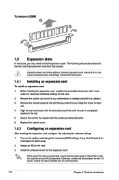
... making the system unstable and the card inoperable. 1-10 Chapter 1: Product introduction Remove the system unit cover (if your motherboard is completely seated on the system and change the necessary BIOS settings, if any. Install the software drivers for information on .... 2. Before installing the expansion card, read the documentation that they support. Align the card connector with the screw you physical injury and damage motherboard components. 1.5.1 Installing an expansion card To install an expansion card: 1. To remove a DIMM B A 1.5 Expansion slots In the future, ...
... making the system unstable and the card inoperable. 1-10 Chapter 1: Product introduction Remove the system unit cover (if your motherboard is completely seated on the system and change the necessary BIOS settings, if any. Install the software drivers for information on .... 2. Before installing the expansion card, read the documentation that they support. Align the card connector with the screw you physical injury and damage motherboard components. 1.5.1 Installing an expansion card To install an expansion card: 1. To remove a DIMM B A 1.5 Expansion slots In the future, ...
User Guide
Page 19
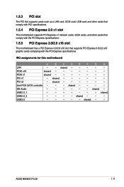
...card, and other cards that comply with PCI specifications. 1.5.4 PCI Express 2.0 x1 slot This motherboard supports PCI Express x1 network cards, SCSI cards, and other cards that comply with the PCI Express specifications.... 1.5.5 PCI Express 3.0/2.0 x16 slot This motherboard has a PCI Express 3.0/2.0 x16 slot that supports PCI Express 3.0/2.0 x16 graphic cards complying with the PCI Express specifications. shared - - - - - - shared USB2.0_2 - - - - IRQ assignments for this motherboard A B CDEF G H LAN - - PCI x1 - ASUS B85M-D PLUS 1-11 shared - - - - - ...
...card, and other cards that comply with PCI specifications. 1.5.4 PCI Express 2.0 x1 slot This motherboard supports PCI Express x1 network cards, SCSI cards, and other cards that comply with the PCI Express specifications.... 1.5.5 PCI Express 3.0/2.0 x16 slot This motherboard has a PCI Express 3.0/2.0 x16 slot that supports PCI Express 3.0/2.0 x16 graphic cards complying with the PCI Express specifications. shared - - - - - - shared USB2.0_2 - - - - IRQ assignments for this motherboard A B CDEF G H LAN - - PCI x1 - ASUS B85M-D PLUS 1-11 shared - - - - - ...
User Guide
Page 24
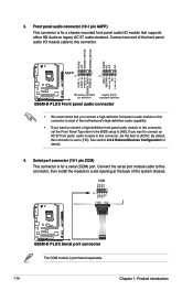
... By default, this connector, then install the module to [HD]. COM PIN 1 RXD DTR DSR CTS DCD TXD GND RTS RI B85M-D PLUS B85M-D PLUS Serial port connector The COM module is for a chassis-mounted front panel audio I/O module that you connect a high-definition front panel audio...port. Front panel audio connector (10-1 pin AAFP) This connector is purchased separately. 1-16 Chapter 1: Product introduction Connect one end of the motherboard's high-definition audio capability. • If you want to connect a high-definition front panel audio module to this connector, set the Front ...
... By default, this connector, then install the module to [HD]. COM PIN 1 RXD DTR DSR CTS DCD TXD GND RTS RI B85M-D PLUS B85M-D PLUS Serial port connector The COM module is for a chassis-mounted front panel audio I/O module that you connect a high-definition front panel audio...port. Front panel audio connector (10-1 pin AAFP) This connector is purchased separately. 1-16 Chapter 1: Product introduction Connect one end of the motherboard's high-definition audio capability. • If you want to connect a high-definition front panel audio module to this connector, set the Front ...
User Guide
Page 25
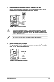
... place jumper caps on the motherboard, ensuring that the black wire of each cable matches the ground pin of maximum 1A (12 W) fan power. 5. The speaker allows you hear system beeps and warnings. These are not jumpers! SPEAKER B85M-D PLUS PIN 1 B85M-D PLUS Speaker connector +5V GND GND Speaker Out ASUS B85M-D PLUS 1-17 CPU and chassis fan...
... place jumper caps on the motherboard, ensuring that the black wire of each cable matches the ground pin of maximum 1A (12 W) fan power. 5. The speaker allows you hear system beeps and warnings. These are not jumpers! SPEAKER B85M-D PLUS PIN 1 B85M-D PLUS Speaker connector +5V GND GND Speaker Out ASUS B85M-D PLUS 1-17 CPU and chassis fan...

User Guide
Page 27
...connectors. Doing so will damage the motherboard! The USB 2.0 module is purchased separately. 10. USB 2.0 connectors (10-1 pin USB1112, USB1314) These connectors are for additional USB 3.0 front or rear panel ports. B85M-D PLUS USB3_12 USB3+5V IntA_P2_SSRXIntA_P2_SSRX+ GND ... NC USB+5V USB_P13USB_P13+ GND NC B85M-D PLUS PIN 1 PIN 1 USB+5V USB_P12USB_P12+ GND USB+5V USB_P14USB_P14+ GND B85M-D PLUS USB2.0 connectors Never connect a 1394 cable to connect a USB 3.0 module for USB 2.0 ports. ASUS B85M-D PLUS 1-19 These USB connectors comply with USB...
...connectors. Doing so will damage the motherboard! The USB 2.0 module is purchased separately. 10. USB 2.0 connectors (10-1 pin USB1112, USB1314) These connectors are for additional USB 3.0 front or rear panel ports. B85M-D PLUS USB3_12 USB3+5V IntA_P2_SSRXIntA_P2_SSRX+ GND ... NC USB+5V USB_P13USB_P13+ GND NC B85M-D PLUS PIN 1 PIN 1 USB+5V USB_P12USB_P12+ GND USB+5V USB_P14USB_P14+ GND B85M-D PLUS USB2.0 connectors Never connect a 1394 cable to connect a USB 3.0 module for USB 2.0 ports. ASUS B85M-D PLUS 1-19 These USB connectors comply with USB...
User Guide
Page 29
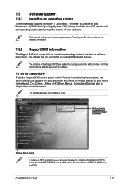
... motherboard supports Windows® 7 (32bit/64bit), Windows® 8 (32bit/64bit) and Windows® 8.1 (32bit/64bit) Operating Systems (OS). The contents of the Support DVD to change at www.asus.com for reference only. Click an icon to display Support DVD/motherboard information Click an item to install If Autorun is enabled in your ASUS motherboard. ASUS B85M-D PLUS...
... motherboard supports Windows® 7 (32bit/64bit), Windows® 8 (32bit/64bit) and Windows® 8.1 (32bit/64bit) Operating Systems (OS). The contents of the Support DVD to change at www.asus.com for reference only. Click an icon to display Support DVD/motherboard information Click an item to install If Autorun is enabled in your ASUS motherboard. ASUS B85M-D PLUS...
User Guide
Page 31
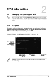
...EZ Update, click EZ Update on the AI Suite 3 main menu bar. BIOS information 2.1 Managing and updating your motherboard's softwares, drivers and the BIOS version easily. ASUS B85M-D PLUS 2-1 With this utlity, you need to restore the BIOS in case you can also manually update the saved BIOS and... select a boot logo when the system goes into POST. Copy the original motherboard BIOS using the ASUS Update utility. 2.1.1 EZ Update ...
...EZ Update, click EZ Update on the AI Suite 3 main menu bar. BIOS information 2.1 Managing and updating your motherboard's softwares, drivers and the BIOS version easily. ASUS B85M-D PLUS 2-1 With this utlity, you need to restore the BIOS in case you can also manually update the saved BIOS and... select a boot logo when the system goes into POST. Copy the original motherboard BIOS using the ASUS Update utility. 2.1.1 EZ Update ...
User Guide
Page 33
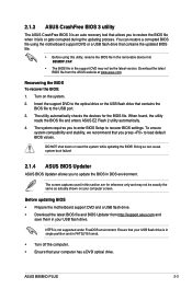
...computer screen. Before updating BIOS • Prepare the motherboard support DVD and a USB flash drive. • Download the latest BIOS file and BIOS Updater from the ASUS website at www.asus.com. Download the latest BIOS file from http://support.asus.com and save them in your computer has a ...2 utility automatically. 4. DO NOT shut down or reset the system while updating the BIOS! NTFS is not supported under FreeDOS environment. ASUS B85M-D PLUS 2-3 The utility automatically checks the devices for reference only and may not be exactly the same as actually shown on the system. 2....
...computer screen. Before updating BIOS • Prepare the motherboard support DVD and a USB flash drive. • Download the latest BIOS file and BIOS Updater from the ASUS website at www.asus.com. Download the latest BIOS file from http://support.asus.com and save them in your computer has a ...2 utility automatically. 4. DO NOT shut down or reset the system while updating the BIOS! NTFS is not supported under FreeDOS environment. ASUS B85M-D PLUS 2-3 The utility automatically checks the devices for reference only and may not be exactly the same as actually shown on the system. 2....

User Guide
Page 36
... setup program. • If the system becomes unstable after changing any BIOS setting, try to clear the CMOS and reset the motherboard to the default value. Do this motherboard. • Ensure that a USB mouse is connected to your data or system. If you always shut down the system properly ...or configure its routines. Entering BIOS Setup at startup To enter BIOS Setup at www.asus.com to download the latest BIOS file for entering the BIOS setup program can cause damage to your motherboard if you failed to enter BIOS Setup using the BIOS Setup program. We recommend ...
... setup program. • If the system becomes unstable after changing any BIOS setting, try to clear the CMOS and reset the motherboard to the default value. Do this motherboard. • Ensure that a USB mouse is connected to your data or system. If you always shut down the system properly ...or configure its routines. Entering BIOS Setup at startup To enter BIOS Setup at www.asus.com to download the latest BIOS file for entering the BIOS setup program can cause damage to your motherboard if you failed to enter BIOS Setup using the BIOS Setup program. We recommend ...
User Guide
Page 37
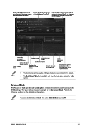
...motherboard temperature, CPU voltage output, and CPU/chassis fan speed Selects the display language of the BIOS setup program Exits the BIOS setup program without saving the changes, saves the changes and resets the system, or enters the Advanced Mode Selects the Advanced mode functions Normal mode ASUS...configure the BIOS settings. Refer to the following sections for experienced end-users to the system. ASUS B85M-D PLUS 2-7 To access the EZ Mode, click Exit, then select ASUS EZ Mode or press F7. Advanced Mode The Advanced Mode provides advanced options for the detailed ...
...motherboard temperature, CPU voltage output, and CPU/chassis fan speed Selects the display language of the BIOS setup program Exits the BIOS setup program without saving the changes, saves the changes and resets the system, or enters the Advanced Mode Selects the Advanced mode functions Normal mode ASUS...configure the BIOS settings. Refer to the following sections for experienced end-users to the system. ASUS B85M-D PLUS 2-7 To access the EZ Mode, click Exit, then select ASUS EZ Mode or press F7. Advanced Mode The Advanced Mode provides advanced options for the detailed ...

User Guide
Page 42
... : xxxxMHz Displays the target DRAM speed. Target Cache Speed : xxxxMHz Displays the target Cache speed. The configuration options for this section vary depending on the motherboard. Scroll down to create/confirm the password. Target CPU Graphics Speed : xxxxMHz Displays the target CPU Graphics speed. 2-12 Chapter 2: Getting started After you clear...
... : xxxxMHz Displays the target DRAM speed. Target Cache Speed : xxxxMHz Displays the target Cache speed. The configuration options for this section vary depending on the motherboard. Scroll down to create/confirm the password. Target CPU Graphics Speed : xxxxMHz Displays the target CPU Graphics speed. 2-12 Chapter 2: Getting started After you clear...


