User Manual
Page 2
... Inc. ("ASUS"). SPECIFICATIONS AND INFORMATION CONTAINED IN THIS MANUAL ARE FURNISHED FOR INFORMATIONAL USE ONLY, AND ARE SUBJECT TO CHANGE AT ANY TIME WITHOUT NOTICE, AND SHOULD NOT BE CONSTRUED AS A COMMITMENT BY ASUS. or (2) for free by downloading it shipped to : ASUSTeK Computer Inc. or (2) the serial number of Certain Software This product may contain copyrighted software that uses the Library...
... Inc. ("ASUS"). SPECIFICATIONS AND INFORMATION CONTAINED IN THIS MANUAL ARE FURNISHED FOR INFORMATIONAL USE ONLY, AND ARE SUBJECT TO CHANGE AT ANY TIME WITHOUT NOTICE, AND SHOULD NOT BE CONSTRUED AS A COMMITMENT BY ASUS. or (2) for free by downloading it shipped to : ASUSTeK Computer Inc. or (2) the serial number of Certain Software This product may contain copyrighted software that uses the Library...
User Manual
Page 8
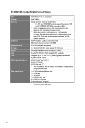
... 3150 Maximum shared memory of 256MB PCIe X4 slot (with X1 speed) 4 x Serial ATA 3Gb/s ports support AHCI mode VIA High Definition Audio 6-channel CODEC Realtek® RTL8111E PCIe Gigabit LAN controller Supports up to 8 USB 2.0/1.1 ports (2 ports at mid-board, 6 ports at back panel) ASUS CrashFree BIOS 3 ASUS EZ Flash 2 ASUS MyLogo 2™ * The actual boot time is subject to hardware configurations and product models. 1 x PS/2 Keyboard/Mouse port 1 x COM port 1 x VGA port 1 x LAN (RJ-45) port 6 x USB 2.0/1.1 ports 6-channel audio I specifications summary CPU Chipset Memory Intel®...
... 3150 Maximum shared memory of 256MB PCIe X4 slot (with X1 speed) 4 x Serial ATA 3Gb/s ports support AHCI mode VIA High Definition Audio 6-channel CODEC Realtek® RTL8111E PCIe Gigabit LAN controller Supports up to 8 USB 2.0/1.1 ports (2 ports at mid-board, 6 ports at back panel) ASUS CrashFree BIOS 3 ASUS EZ Flash 2 ASUS MyLogo 2™ * The actual boot time is subject to hardware configurations and product models. 1 x PS/2 Keyboard/Mouse port 1 x COM port 1 x VGA port 1 x LAN (RJ-45) port 6 x USB 2.0/1.1 ports 6-channel audio I specifications summary CPU Chipset Memory Intel®...
User Manual
Page 9
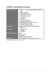
... supports additional 2 USB 2.0/1.1 ports 1 x CPU fan connector 1 x Chassis fan connector 1 x Chassis intrusion connector 1 x TPM connector (optional) 1 x LPT connector 1 x 18bit LVDS 1 x S/PDIF Out connector 1 x Front panel audio connector 1 x High Definition front panel audio connector 1 x 24-pin EATX power connector 1 x 4-pin ATX 12V power connector 8 Mb Flash ROM, AMI BIOS, PnP, DMI2.0, WfM2.0, SMBIOS 2.5 2 x Serial ATA cable 1 x I/O shield 1 x User Manual BIOS features Accessories Support DVD contents Form Factor Drivers ASUS PC Probe II ASUS Update Anti-virus software (OEM version...
... supports additional 2 USB 2.0/1.1 ports 1 x CPU fan connector 1 x Chassis fan connector 1 x Chassis intrusion connector 1 x TPM connector (optional) 1 x LPT connector 1 x 18bit LVDS 1 x S/PDIF Out connector 1 x Front panel audio connector 1 x High Definition front panel audio connector 1 x 24-pin EATX power connector 1 x 4-pin ATX 12V power connector 8 Mb Flash ROM, AMI BIOS, PnP, DMI2.0, WfM2.0, SMBIOS 2.5 2 x Serial ATA cable 1 x I/O shield 1 x User Manual BIOS features Accessories Support DVD contents Form Factor Drivers ASUS PC Probe II ASUS Update Anti-virus software (OEM version...
User Manual
Page 12
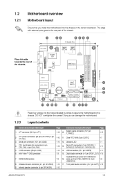
... power and USB device wake-up (3-pin PS2_USBPW1-6, 3-pin USBPW7-8) Page 1-12 1-7 1-1 1-11 1-11 Connectors/Jumpers/Slots/LED LPT connector (26-1 pin LPT ) ATX power connectors (24-pin EATXPWR, 4-pin ATX12V) Serial port connector (10-1 pin COM2) CPU and chassis fan connectors (4-pin CPU_FAN, 4-pin CHA_FAN) LVDS connector (30-pin LVDS) Intel® Atom™ D425 processor DDR3 DIMM sockets Chassis intrusion connector (4-1 pin CHASSIS) Internal speaker connector (4-pin SPEAKER) Digital audio connector (4-1 pin SPDIF_OUT) 1-15 1-8 Front panel audio connector (10-1 pin AAFP) 1-13 ASUS AT4NM10T...
... power and USB device wake-up (3-pin PS2_USBPW1-6, 3-pin USBPW7-8) Page 1-12 1-7 1-1 1-11 1-11 Connectors/Jumpers/Slots/LED LPT connector (26-1 pin LPT ) ATX power connectors (24-pin EATXPWR, 4-pin ATX12V) Serial port connector (10-1 pin COM2) CPU and chassis fan connectors (4-pin CPU_FAN, 4-pin CHA_FAN) LVDS connector (30-pin LVDS) Intel® Atom™ D425 processor DDR3 DIMM sockets Chassis intrusion connector (4-1 pin CHASSIS) Internal speaker connector (4-pin SPEAKER) Digital audio connector (4-1 pin SPDIF_OUT) 1-15 1-8 Front panel audio connector (10-1 pin AAFP) 1-13 ASUS AT4NM10T...
User Manual
Page 16
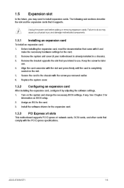
... the slot. Install the software drivers for later use . Replace the system cover. 1.5.2 1. 2. 3. Keep the screw for the expansion card. Unplug the power cord before adding or removing expansion cards. Configuring an expansion card 1.5.3 This motherboard supports PCI Express x4 network cards, SCSI cards, and other cards that it by adjusting the software settings. The following sub‑sections describe the slot and the expansion cards that comply with the screw you removed earlier. PCI Express x4 slots ASUS AT4NM10T-I 1-6
... the slot. Install the software drivers for later use . Replace the system cover. 1.5.2 1. 2. 3. Keep the screw for the expansion card. Unplug the power cord before adding or removing expansion cards. Configuring an expansion card 1.5.3 This motherboard supports PCI Express x4 network cards, SCSI cards, and other cards that it by adjusting the software settings. The following sub‑sections describe the slot and the expansion cards that comply with the screw you removed earlier. PCI Express x4 slots ASUS AT4NM10T-I 1-6
User Manual
Page 18
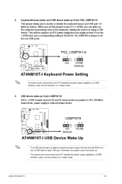
... or using a USB device. When you set this jumper to pins 2-3 (+5VSB), you to CPU, DRAM in slow refresh, power supply in sleep mode. 3. ASUS AT4NM10T-I Keyboard Power Setting The total current consumed must NOT exceed the power supply capability (+5VSB) whether under normal condition or in reduced power mode). Set to +5VSB to wake up from S3 and S4 sleep modes (no power to enable or disable the keyboard/mouse and USB port 1-6 wake-up (3-pin PS2_USBPW1-6) PS2_USBPW1-6 1 AT4NM10T-I 2 2 3 +5V +5VSB (Default) AT4NM10T-I 1-8 2. Keyboard/mouse power and USB device wake...
... or using a USB device. When you set this jumper to pins 2-3 (+5VSB), you to CPU, DRAM in slow refresh, power supply in sleep mode. 3. ASUS AT4NM10T-I Keyboard Power Setting The total current consumed must NOT exceed the power supply capability (+5VSB) whether under normal condition or in reduced power mode). Set to +5VSB to wake up from S3 and S4 sleep modes (no power to enable or disable the keyboard/mouse and USB port 1-6 wake-up (3-pin PS2_USBPW1-6) PS2_USBPW1-6 1 AT4NM10T-I 2 2 3 +5V +5VSB (Default) AT4NM10T-I 1-8 2. Keyboard/mouse power and USB device wake...
User Manual
Page 20
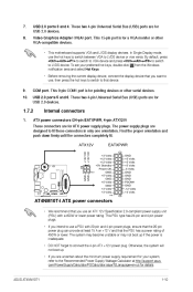
... fit. These two 4-pin Universal Serial Bus (USB) ports are uncertain about the minimum power supply requirement for a VGA monitor or other serial devices. 10. Internal connectors ATX power connectors (24-pin EATXPWR, 4-pin ATX12V) These connectors are designed to that you use an ATX 12V Specification 2.0‑compliant power supply unit (PSU) with 20-pin and 4-pin power plugs, ensure that the 20-pin power plug can provide at http://support.asus. The system may become unstable or may not boot up . •...
... fit. These two 4-pin Universal Serial Bus (USB) ports are uncertain about the minimum power supply requirement for a VGA monitor or other serial devices. 10. Internal connectors ATX power connectors (24-pin EATXPWR, 4-pin ATX12V) These connectors are designed to that you use an ATX 12V Specification 2.0‑compliant power supply unit (PSU) with 20-pin and 4-pin power plugs, ensure that the 20-pin power plug can provide at http://support.asus. The system may become unstable or may not boot up . •...
User Manual
Page 21
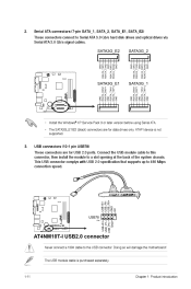
... 480 Mbps connection speed. This USB connector complys with USB 2.0 specification that supports up to a slot opening at the back of the system chassis. ATAPI device is purchased separately. 1-11 USB+5V USB_P7USB_P7+ GND USB+5V USB_P8USB_P8+ GND NC GND RSATA_TXP2 RSATA_TXN2 GND RSATA_RXP2 RSATA_RXN2 GND Chapter 1: Product introduction USB connectors (10-1 pin USB78) AT4NM10T-I USB78 PIN 1 AT4NM10T-I SATA 3.0Gb/s connectors • Install the Windows® XP Service Pack 3 or later version before using Serial ATA...
... 480 Mbps connection speed. This USB connector complys with USB 2.0 specification that supports up to a slot opening at the back of the system chassis. ATAPI device is purchased separately. 1-11 USB+5V USB_P7USB_P7+ GND USB+5V USB_P8USB_P8+ GND NC GND RSATA_TXP2 RSATA_TXN2 GND RSATA_RXP2 RSATA_RXN2 GND Chapter 1: Product introduction USB connectors (10-1 pin USB78) AT4NM10T-I USB78 PIN 1 AT4NM10T-I SATA 3.0Gb/s connectors • Install the Windows® XP Service Pack 3 or later version before using Serial ATA...
User Manual
Page 27
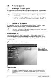
... for updates. Visit the ASUS website at any time without notice. Click Drivers, Utilities, Make Disk, Manual, and Contact tabs to locate the file ASSETUP.EXE from the BIN folder. The following screen is NOT enabled in your computer, the DVD automatically displays the Specials screen which contains the unique feature of your hardware. • Motherboard settings and hardware options vary. 1.8 1.8.1 Software support Installing an operating system This motherboard supports Windows®...
... for updates. Visit the ASUS website at any time without notice. Click Drivers, Utilities, Make Disk, Manual, and Contact tabs to locate the file ASSETUP.EXE from the BIN folder. The following screen is NOT enabled in your computer, the DVD automatically displays the Specials screen which contains the unique feature of your hardware. • Motherboard settings and hardware options vary. 1.8 1.8.1 Software support Installing an operating system This motherboard supports Windows®...
User Manual
Page 28
... the support DVD in the support DVD that allows you to avoid network traffic, or click Auto Select then click Next. Follow the onscreen instructions to launch the ASUS Update utility. From the Windows® desktop, click Start > Programs > ASUS > ASUSUpdate > ASUSUpdate to complete the installation. c. ASUS Update utility Installing ASUS Update To install ASUS Update: 1. 2. 3. Quit all Windows® applications before you to manage, save, and update the motherboard BIOS in Windows® environment. • ASUS Update requires an Internet connection...
... the support DVD in the support DVD that allows you to avoid network traffic, or click Auto Select then click Next. Follow the onscreen instructions to launch the ASUS Update utility. From the Windows® desktop, click Start > Programs > ASUS > ASUSUpdate > ASUSUpdate to complete the installation. c. ASUS Update utility Installing ASUS Update To install ASUS Update: 1. 2. 3. Quit all Windows® applications before you to manage, save, and update the motherboard BIOS in Windows® environment. • ASUS Update requires an Internet connection...
User Manual
Page 29
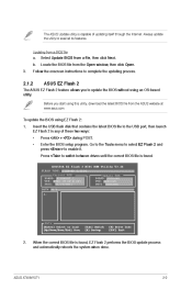
... PATH: A:\ Note [Enter] Select or Load [Up/Down/Home/End] Move [Tab] Switch [B] Backup [V] Drive Info [ESC] Exit 2. Insert the USB flash disk that contains the latest BIOS file to update the BIOS without using an OS‑based utility. ASUSTek EZ Flash 2 BIOS ROM Utility V3.44 FLASH TYPE: WINBOND W25P80 Current ROM BOARD: AT4NM10T-I 2-2 Follow the onscreen instructions to switch between drives until the correct BIOS file is found . Enter the BIOS setup program. The ASUS Update utility is capable of...
... PATH: A:\ Note [Enter] Select or Load [Up/Down/Home/End] Move [Tab] Switch [B] Backup [V] Drive Info [ESC] Exit 2. Insert the USB flash disk that contains the latest BIOS file to update the BIOS without using an OS‑based utility. ASUSTek EZ Flash 2 BIOS ROM Utility V3.44 FLASH TYPE: WINBOND W25P80 Current ROM BOARD: AT4NM10T-I 2-2 Follow the onscreen instructions to switch between drives until the correct BIOS file is found . Enter the BIOS setup program. The ASUS Update utility is capable of...
User Manual
Page 30
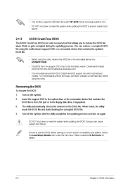
... system boot failure! Turn on again. For motherboards without the floppy connector, prepare a USB flash disk before using this utility. The utility automatically checks the devices for details. 2-3 Chapter 2: BIOS information Download the latest BIOS file from the ASUS website at www.asus.com. • The removable device that contains the updated BIOS file. • Before using this utility, rename the BIOS file in the removable device into AT4NM10T.ROM. • The BIOS file in the support DVD may not be the latest version. Ensure to load the BIOS default settings...
... system boot failure! Turn on again. For motherboards without the floppy connector, prepare a USB flash disk before using this utility. The utility automatically checks the devices for details. 2-3 Chapter 2: BIOS information Download the latest BIOS file from the ASUS website at www.asus.com. • The removable device that contains the updated BIOS file. • Before using this utility, rename the BIOS file in the removable device into AT4NM10T.ROM. • The BIOS file in the support DVD may not be the latest version. Ensure to load the BIOS default settings...

User Manual
Page 32
... detects the values opposite the dimmed items (Device, Vendor, Size, LBA Mode, Block Mode, PIO Mode, Async DMA, Ultra DMA, and SMART Monitoring). 2.3 When you enter the BIOS Setup program, the Main menu screen appears, giving you are not user-configurable. Configuration options: [Not Installed] [Auto] [CDROM] [ARMD] LBA/Large Mode [Auto] Enables or disables the LBA mode. These values are specifically configuring a CD-ROM drive. Use [+] or [-] to select a field. Main Advanced Power AT4NM10T-I BIOS Setup Boot Tools Exit [00:31:48] [Tue 03...
... detects the values opposite the dimmed items (Device, Vendor, Size, LBA Mode, Block Mode, PIO Mode, Async DMA, Ultra DMA, and SMART Monitoring). 2.3 When you enter the BIOS Setup program, the Main menu screen appears, giving you are not user-configurable. Configuration options: [Not Installed] [Auto] [CDROM] [ARMD] LBA/Large Mode [Auto] Enables or disables the LBA mode. These values are specifically configuring a CD-ROM drive. Use [+] or [-] to select a field. Main Advanced Power AT4NM10T-I BIOS Setup Boot Tools Exit [00:31:48] [Tue 03...
User Manual
Page 33
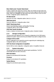
... configure the item. Displays the auto-detected CPU specification. Block (Multi-sector Transfer) Mode [Auto] Enables or disables data multi-sectors transfers. When set or change the configurations for the Serial ATA connectors supported by the Southbridge chip. Configuration options: [Disabled] [Enabled] 2.3.4 The items in this menu. Configuration options: [Auto] SMART Monitoring [Auto] Sets the Smart Monitoring, Analysis, and Reporting Technology. The BIOS automatically detects the items in the system. System Information BIOS Information Processor Displays the auto...
... configure the item. Displays the auto-detected CPU specification. Block (Multi-sector Transfer) Mode [Auto] Enables or disables data multi-sectors transfers. When set or change the configurations for the Serial ATA connectors supported by the Southbridge chip. Configuration options: [Disabled] [Enabled] 2.3.4 The items in this menu. Configuration options: [Auto] SMART Monitoring [Auto] Sets the Smart Monitoring, Analysis, and Reporting Technology. The BIOS automatically detects the items in the system. System Information BIOS Information Processor Displays the auto...

User Manual
Page 34
CPU Configuration Max CPUID Value Limit [Disabled] Allows you to determine whether to use as Windows NT4.0. Configuration options: [Disabled] [Enabled] 2.4.2 The Chipset menu allows you to change the settings for the CPU and other system devices. Chipset North Bridge Configuration Initiate Graphic Adapter [PCIE/IGD] Allows you to decide which graphics controller to limit CPUID maximum value. Configuration options: [Disabled] [Enabled] Hyper Threading Technology [Enabled] Allows you to zero (0). AT4NM10T-I BIOS Setup Boot Tools Exit Version 0306 Configure CPU. Set ...
CPU Configuration Max CPUID Value Limit [Disabled] Allows you to determine whether to use as Windows NT4.0. Configuration options: [Disabled] [Enabled] 2.4.2 The Chipset menu allows you to change the settings for the CPU and other system devices. Chipset North Bridge Configuration Initiate Graphic Adapter [PCIE/IGD] Allows you to decide which graphics controller to limit CPUID maximum value. Configuration options: [Disabled] [Enabled] Hyper Threading Technology [Enabled] Allows you to zero (0). AT4NM10T-I BIOS Setup Boot Tools Exit Version 0306 Configure CPU. Set ...
User Manual
Page 35
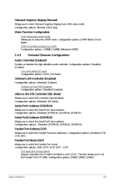
...set to select ATA Controller Operate Mode. Configuration options: [Normal] [LVDS only] Video Function Configruation DVMT Mode Select [DVMT Mode] Allows you to select Onboard Graphics Display from LVDS only or both. Onboard Graphics Display [Normal] Allows you to select the DVMT mode. Configuration options: [Disabled] [Enabled] Front Panel Select [HD Audio] Configuration options: [AC97] [HD Audio] OnBoard LAN Controller [Enabled] OnBoard LAN Boot ROM [Disabled] Configuration options: [Disabled] [Enabled] Configuration options: [Disabled] [Enabled] JMicron 36x ATA Controller [IDE Mode...
...set to select ATA Controller Operate Mode. Configuration options: [Normal] [LVDS only] Video Function Configruation DVMT Mode Select [DVMT Mode] Allows you to select Onboard Graphics Display from LVDS only or both. Onboard Graphics Display [Normal] Allows you to select the DVMT mode. Configuration options: [Disabled] [Enabled] Front Panel Select [HD Audio] Configuration options: [AC97] [HD Audio] OnBoard LAN Controller [Enabled] OnBoard LAN Boot ROM [Disabled] Configuration options: [Disabled] [Enabled] Configuration options: [Disabled] [Enabled] JMicron 36x ATA Controller [IDE Mode...

User Manual
Page 36
... controller legacy mode is disabled. If no USB device is detected, the legacy USB support is enabled. Configuration options: [Disabled] [Enabled] USB 2.0 Controller [Enabled] Legacy USB Support [Auto] Allows you to enable or disable support for Legacy USB storage devices, including USB flash drives and USB hard drives. Configuration options: [FullSpeed] [HiSpeed] The following items may only appear when a USB storage device is detected, the item shows None. Select an item then press to detect the presence of USB devices at startup. Setting to [Auto] allows the system to display...
... controller legacy mode is disabled. If no USB device is detected, the legacy USB support is enabled. Configuration options: [Disabled] [Enabled] USB 2.0 Controller [Enabled] Legacy USB Support [Auto] Allows you to enable or disable support for Legacy USB storage devices, including USB flash drives and USB hard drives. Configuration options: [FullSpeed] [HiSpeed] The following items may only appear when a USB storage device is detected, the item shows None. Select an item then press to detect the presence of USB devices at startup. Setting to [Auto] allows the system to display...
User Manual
Page 37
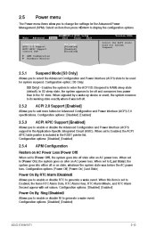
... Power Management (APM). 2.5 Power menu The Power menu items allow you to add more tables for Advanced Configuration and Power Interface (ACPI) 2.0 specifications. Select an item then press to its working state exactly where it was before the AC power loss. Configuration options: [Disabled] [Enabled] ASUS AT4NM10T-I BIOS Setup Boot Tools Exit [S3 only] [Disabled] [Enabled] [Disabled] Version 0306 Select the ACPI state used for system suspend. When set to be off . Main Advanced Power AT4NM10T-I 2-10 When signaled by a wake...
... Power Management (APM). 2.5 Power menu The Power menu items allow you to add more tables for Advanced Configuration and Power Interface (ACPI) 2.0 specifications. Select an item then press to its working state exactly where it was before the AC power loss. Configuration options: [Disabled] [Enabled] ASUS AT4NM10T-I BIOS Setup Boot Tools Exit [S3 only] [Disabled] [Enabled] [Disabled] Version 0306 Select the ACPI state used for system suspend. When set to be off . Main Advanced Power AT4NM10T-I 2-10 When signaled by a wake...
User Manual
Page 39
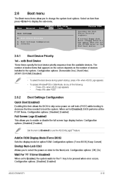
... the F1 key to enable or disable the full screen logo display feature. Configuration options: [Disabled] [Enabled] ASUS AT4NM10T-I BIOS Setup Boot Tools Exit Version 0306 Specifies the Boot Device Priority sequence. Main Advanced Power AT4NM10T-I 2-12 The number of the following: • Press when ASUS Logo appears. • Press after POST. 2.6.2 Boot Settings Configuration Quick Boot [Enabled] Enabling this item to [Enabled] to boot the system. AddOn ROM Display Mode [Force BIOS] Bootup Num-Lock [On] Sets the display mode for the NumLock. Configuration options: [Off] [On...
... the F1 key to enable or disable the full screen logo display feature. Configuration options: [Disabled] [Enabled] ASUS AT4NM10T-I BIOS Setup Boot Tools Exit Version 0306 Specifies the Boot Device Priority sequence. Main Advanced Power AT4NM10T-I 2-12 The number of the following: • Press when ASUS Logo appears. • Press after POST. 2.6.2 Boot Settings Configuration Quick Boot [Enabled] Enabling this item to [Enabled] to boot the system. AddOn ROM Display Mode [Force BIOS] Bootup Num-Lock [On] Sets the display mode for the NumLock. Configuration options: [Off] [On...

User Manual
Page 41
When set to clear the user password. Use the left/right arrow key to select between [Yes] or [No], then press to select and update BIOS. Clear User Password Select this item to [Always], BIOS checks for special functions. This utility supports 1.FAT 12/16/32(r/w) 2.NTFS(read only) 3.CD-DISC(read only) ASUS EZ Flash 2 2.7.1 Allows you to display the sub-menu. ASUS EZ Flash 2 ASUS AT4NM10T-I BIOS Setup Boot Tools Exit Version 0306 Press ENTER to...
When set to clear the user password. Use the left/right arrow key to select between [Yes] or [No], then press to select and update BIOS. Clear User Password Select this item to [Always], BIOS checks for special functions. This utility supports 1.FAT 12/16/32(r/w) 2.NTFS(read only) 3.CD-DISC(read only) ASUS EZ Flash 2 2.7.1 Allows you to display the sub-menu. ASUS EZ Flash 2 ASUS AT4NM10T-I BIOS Setup Boot Tools Exit Version 0306 Press ENTER to...


