Owners Manual
Page 3
... camera......... 18 3. Installing the Control Unit 21 Connections 22 System Example 24 Connecting a product that has the direct camera input connector 24 Connecting a product that has RCA video input terminals 24 Confirmation 25 Calibration Introduction 26 What is Detected 10 Moving object verification icon 10 Camera Image 11 About the rear camera guide 12 Error between "Calibration Mode" and "Normal Use Mode 26 Preparation 26 Accessory parts 26 Necessary tools 26 Necessary space for work...
... camera......... 18 3. Installing the Control Unit 21 Connections 22 System Example 24 Connecting a product that has the direct camera input connector 24 Connecting a product that has RCA video input terminals 24 Confirmation 25 Calibration Introduction 26 What is Detected 10 Moving object verification icon 10 Camera Image 11 About the rear camera guide 12 Error between "Calibration Mode" and "Normal Use Mode 26 Preparation 26 Accessory parts 26 Necessary tools 26 Necessary space for work...
Owners Manual
Page 4
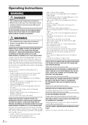
...driver in an accident. MINIMIZE DISPLAY VIEWING WHILE DRIVING. KEEP SMALL OBJECTS SUCH AS BOLTS OR SCREWS OUT OF THE REACH OF CHILDREN. Swallowing them can scan • non-moving • when an object approaches the vehicle from very dark to very bright light...THE CAR IN A LEVEL, SAFE PLACE, TURNING OFF THE ENGINE, AND APPLYING THE HAND BRAKE. SERIOUS INJURY OR DEATH CAN RESULT. WHEN INSTALLING CAMERA AND/OR OBJECT SENSOR, BE SURE TO USE SPECIFIC VEHICLE CALIBRATION KIT OTHERWISE IT WILL NOT ACCURATELY DISPLAY IMAGES. USE THE CORRECT AMPERE RATING WHEN REPLACING FUSES. Failure...
...driver in an accident. MINIMIZE DISPLAY VIEWING WHILE DRIVING. KEEP SMALL OBJECTS SUCH AS BOLTS OR SCREWS OUT OF THE REACH OF CHILDREN. Swallowing them can scan • non-moving • when an object approaches the vehicle from very dark to very bright light...THE CAR IN A LEVEL, SAFE PLACE, TURNING OFF THE ENGINE, AND APPLYING THE HAND BRAKE. SERIOUS INJURY OR DEATH CAN RESULT. WHEN INSTALLING CAMERA AND/OR OBJECT SENSOR, BE SURE TO USE SPECIFIC VEHICLE CALIBRATION KIT OTHERWISE IT WILL NOT ACCURATELY DISPLAY IMAGES. USE THE CORRECT AMPERE RATING WHEN REPLACING FUSES. Failure...
Owners Manual
Page 5
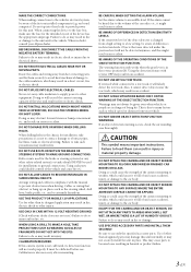
... FUNCTION. This is changed from a high setting to provide power for installation, take such precautions may result in a short circuit, fire or electric shock. USE SPECIFIED ACCESSORY PARTS AND INSTALL THEM SECURELY. This may result in doubt, consult your Alpine dealer. MAKE THE CORRECT CONNECTIONS. DO NOT SPLICE INTO ELECTRICAL CABLES. DO NOT INSTALL IN LOCATIONS WHICH MIGHT HINDER VEHICLE OPERATION, SUCH AS...
... FUNCTION. This is changed from a high setting to provide power for installation, take such precautions may result in a short circuit, fire or electric shock. USE SPECIFIED ACCESSORY PARTS AND INSTALL THEM SECURELY. This may result in doubt, consult your Alpine dealer. MAKE THE CORRECT CONNECTIONS. DO NOT SPLICE INTO ELECTRICAL CABLES. DO NOT INSTALL IN LOCATIONS WHICH MIGHT HINDER VEHICLE OPERATION, SUCH AS...
Owners Manual
Page 6
... the car body, requiring use a mobile phones or wireless devices away from deteriorating, wipe with a chemical-free, damp cloth. • When washing the vehicle, do not apply unnecessary force to have the work done. When in battery failure, performance failure, connector damage, or wire breakage. • About Power Connection Connect a reverse input cable (orange/white) to the wiring. Return it to provide power for repairing. If the camera...
... the car body, requiring use a mobile phones or wireless devices away from deteriorating, wipe with a chemical-free, damp cloth. • When washing the vehicle, do not apply unnecessary force to have the work done. When in battery failure, performance failure, connector damage, or wire breakage. • About Power Connection Connect a reverse input cable (orange/white) to the wiring. Return it to provide power for repairing. If the camera...
Owners Manual
Page 7
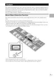
... function helps to "Adjusting Detection Sensitivity" (page 16). 5-EN The object detection function is a visual and audible warning given for the rear view. A separately installed monitor is placed in the following situations: • When you reverse the car to "Adjusting Alarm Volume" (page 16). • You can adjust the volume of the area behind the vehicle. Feature This camera system displays a live video...
... function helps to "Adjusting Detection Sensitivity" (page 16). 5-EN The object detection function is a visual and audible warning given for the rear view. A separately installed monitor is placed in the following situations: • When you reverse the car to "Adjusting Alarm Volume" (page 16). • You can adjust the volume of the area behind the vehicle. Feature This camera system displays a live video...
Owners Manual
Page 13
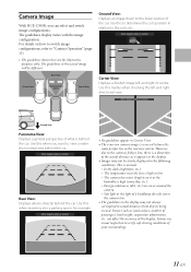
... centre. This is high or low. - Always use visual inspection to view a wider than normal area behind the car. Use this when reversing into a parking space, for illustrative purposes only. Rear View: Displays what is high (rainy day, etc.). - The temperature near the lens is normal. - Camera Image With HCE-C300R, you want to verify safe driving conditions of...
... centre. This is high or low. - Always use visual inspection to view a wider than normal area behind the car. Use this when reversing into a parking space, for illustrative purposes only. Rear View: Displays what is high (rainy day, etc.). - The temperature near the lens is normal. - Camera Image With HCE-C300R, you want to verify safe driving conditions of...
Owners Manual
Page 17
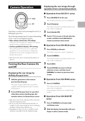
... to the owner's manual of the connected monitor/navigation system. • Be sure to also check behind and around the car. • Depending on where the unit is installed, actual conditions may be required depending on the connected navigation/monitor. • Rear camera connection: ON setting Setting to display the camera image on the unit. The VISUAL selection screen is displayed. 2 Touch [Camera]. e Operation from connected products VIEW SET. The Camera mode is...
... to the owner's manual of the connected monitor/navigation system. • Be sure to also check behind and around the car. • Depending on where the unit is installed, actual conditions may be required depending on the connected navigation/monitor. • Rear camera connection: ON setting Setting to display the camera image on the unit. The VISUAL selection screen is displayed. 2 Touch [Camera]. e Operation from connected products VIEW SET. The Camera mode is...

Owners Manual
Page 18
... configuration changes every time VIEW is "High." 1 Press and hold SET. The default is pressed. The sensitivity adjustment screen appears. 3 Press SET. Ground View Adjusting Alarm Volume The audible warning has 3 selectable volume levels. Almost no motionless objects are detected. Detects moving objects. Use with the appropriate volume level. 16-EN The default is the "Middle" setting. 1 Press and hold SET. Pressing the button toggles the volume level. Changing the Rear...
... configuration changes every time VIEW is "High." 1 Press and hold SET. The default is pressed. The sensitivity adjustment screen appears. 3 Press SET. Ground View Adjusting Alarm Volume The audible warning has 3 selectable volume levels. Almost no motionless objects are detected. Detects moving objects. Use with the appropriate volume level. 16-EN The default is the "Middle" setting. 1 Press and hold SET. Pressing the button toggles the volume level. Changing the Rear...
Owners Manual
Page 19
... operation switch (page 20) Checking the installation location of a short circuit. • Be sure to connect the colour coded leads according to the diagram. The system cannot be used with a different camera. • This product cannot be installed in or used with anything other than a car (in doubt, consult your Alpine dealer. • Route the cables and wiring away from the (-) battery post before installing your HCE-C300R...
... operation switch (page 20) Checking the installation location of a short circuit. • Be sure to connect the colour coded leads according to the diagram. The system cannot be used with a different camera. • This product cannot be installed in or used with anything other than a car (in doubt, consult your Alpine dealer. • Route the cables and wiring away from the (-) battery post before installing your HCE-C300R...
Owners Manual
Page 20
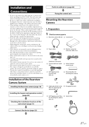
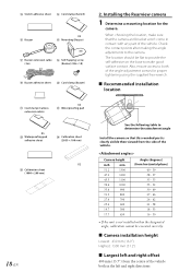
.... Installing the Rearview camera 1 Determine a mounting location for proper tightening using the supplied hex wrench. e Recommended installation location See the following table to the camera. M Switch adhesive sheet N Cord clamp (Switch) O Buzzer X3 P Mounting (Buzzer) Q Buzzer extension cable R Self-Tapping screw (3m) (Buzzer) (M6 × 10) S Buzzer adhesive sheet T Cord clamp (Buzzer) U Cord clamp (Camera extension cable) X3 V Waterproofing pad X5 W Waterproofing pad adhesive sheet X Calibration sheet...
.... Installing the Rearview camera 1 Determine a mounting location for proper tightening using the supplied hex wrench. e Recommended installation location See the following table to the camera. M Switch adhesive sheet N Cord clamp (Switch) O Buzzer X3 P Mounting (Buzzer) Q Buzzer extension cable R Self-Tapping screw (3m) (Buzzer) (M6 × 10) S Buzzer adhesive sheet T Cord clamp (Buzzer) U Cord clamp (Camera extension cable) X3 V Waterproofing pad X5 W Waterproofing pad adhesive sheet X Calibration sheet...

Owners Manual
Page 21
... cable should be possible. 2 Installing the camera and the camera mounting bracket to the car. Apply touch-up . • Ensure the cable does not get caught in the trunk, rear door(s) or any slack cable around the waterproof pad V using the cord clamp U. e Attaching the Camera Reverse In Camera cable Angle adjustment screw Make sure that the camera cable is facing directly behind the vehicle. (5) Pull the camera cable...
... cable should be possible. 2 Installing the camera and the camera mounting bracket to the car. Apply touch-up . • Ensure the cable does not get caught in the trunk, rear door(s) or any slack cable around the waterproof pad V using the cord clamp U. e Attaching the Camera Reverse In Camera cable Angle adjustment screw Make sure that the camera cable is facing directly behind the vehicle. (5) Pull the camera cable...

Owners Manual
Page 24
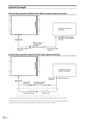
... In lead To Video Input Connector when connecting with the navigation or monitor that has no direct camera input connector To the direct camera input connector of the navigation or monitor Switch (Included) Buzzer extension Buzzer cable (3m) (included) (Included) Camera extension Rearview camera cable (8m) (Included) (Included) REAR 22-EN Connections N A (Red) (Yellow) D (Black) ACC B BATT C GND E (Orange/White) REVERSE F (Orange/Black) CAMERA CONTROL G (Bright Green) ALERT OUT H VIDEO OUTPUT I REAR CAMERA OUT J * Currently not used.
... In lead To Video Input Connector when connecting with the navigation or monitor that has no direct camera input connector To the direct camera input connector of the navigation or monitor Switch (Included) Buzzer extension Buzzer cable (3m) (included) (Included) Camera extension Rearview camera cable (8m) (Included) (Included) REAR 22-EN Connections N A (Red) (Yellow) D (Black) ACC B BATT C GND E (Orange/White) REVERSE F (Orange/Black) CAMERA CONTROL G (Bright Green) ALERT OUT H VIDEO OUTPUT I REAR CAMERA OUT J * Currently not used.
Owners Manual
Page 25
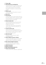
... used. Switches the video picture to the rearview camera. I Video Output Connector (Yellow) Connects to the Video Input Connector when connecting with the gear lever shifted into reverse (R). D Fuse 7.5A E Ground Lead Connect this switch when calibration is securely fastened using the sheet metal screw provided. F Reverse Input Lead Connect to the plus side of the car's reverse lamp that has no direct camera input connector. G Camera Control Lead Use to connect with products that do not have the camera screen display...
... used. Switches the video picture to the rearview camera. I Video Output Connector (Yellow) Connects to the Video Input Connector when connecting with the gear lever shifted into reverse (R). D Fuse 7.5A E Ground Lead Connect this switch when calibration is securely fastened using the sheet metal screw provided. F Reverse Input Lead Connect to the plus side of the car's reverse lamp that has no direct camera input connector. G Camera Control Lead Use to connect with products that do not have the camera screen display...
Owners Manual
Page 26
... Cable (Sold Separately) Video Input Connector Orange/Black Camera Control Lead Orange/White Reverse Lead IVA-W520 series, etc. * Use this connection for products which only have a Reverse lead trigger for the camera display. • When you route and arrange cables around the vehicle interior, do so as to avoid hot/moving parts. • Connect the cameras by referring carefully to connection instructions or labels. 24-EN Direct Camera Input Connector Connecting...
... Cable (Sold Separately) Video Input Connector Orange/Black Camera Control Lead Orange/White Reverse Lead IVA-W520 series, etc. * Use this connection for products which only have a Reverse lead trigger for the camera display. • When you route and arrange cables around the vehicle interior, do so as to avoid hot/moving parts. • Connect the cameras by referring carefully to connection instructions or labels. 24-EN Direct Camera Input Connector Connecting...

Owners Manual
Page 27
Also check for damage from sharp edges or protrusions. Installing the Rearview camera." (page 18) 2 Connect the battery (-) terminal. 3 Turn on the engine key. Make sure leads are not pinched by referring to "2. Refer to the Owner's Manual. 4 Make sure all factory components such as the seat rail, etc. Make sure the unit is operating correctly by moving parts such as the brake lamps, etc., work correctly. 25-EN Confirmation 1 Securing leads, etc.
Also check for damage from sharp edges or protrusions. Installing the Rearview camera." (page 18) 2 Connect the battery (-) terminal. 3 Turn on the engine key. Make sure leads are not pinched by referring to "2. Refer to the Owner's Manual. 4 Make sure all factory components such as the seat rail, etc. Make sure the unit is operating correctly by moving parts such as the brake lamps, etc., work correctly. 25-EN Confirmation 1 Securing leads, etc.
Owners Manual
Page 28
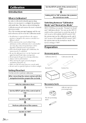
... install data. Calibration must be performed. • If the vehicle height changes after calibration, the system must be degraded. Set the SETUP switch of the control unit to ON with the navigation/monitor, prepare the car body. You can be set to "ON." Set the SETUP switch of the control unit to switch the mode. Also, the warning message language and the cm/ inch selection can use the SETUP switch on the control unit...
... install data. Calibration must be performed. • If the vehicle height changes after calibration, the system must be degraded. Set the SETUP switch of the control unit to ON with the navigation/monitor, prepare the car body. You can be set to "ON." Set the SETUP switch of the control unit to switch the mode. Also, the warning message language and the cm/ inch selection can use the SETUP switch on the control unit...
Owners Manual
Page 33
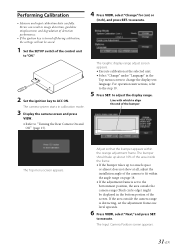
... VIEW, select "Change" for (cm) or (Inch), and press SET. The bumper should take up about 10% of the screen. Performing Calibration • Measure and input calibration data carefully. If the area outside the camera range (black circle edge) might be saved. 1 Set the SETUP switch of the bumper The Top menu screen appears. The Input Camera Position screen appears. 31-EN Errors can result in calibration mode. 3 Display the camera screen and press VIEW. •...
... VIEW, select "Change" for (cm) or (Inch), and press SET. The bumper should take up about 10% of the screen. Performing Calibration • Measure and input calibration data carefully. If the area outside the camera range (black circle edge) might be saved. 1 Set the SETUP switch of the bumper The Top menu screen appears. The Input Camera Position screen appears. 31-EN Errors can result in calibration mode. 3 Display the camera screen and press VIEW. •...
Owners Manual
Page 35
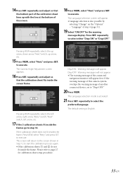
... connected device, set to "Disp/OFF:" 20 Press VIEW. Pressing VIEW repeatedly selects the left arrow, right arrow, "Retry" switch, "Next" switch, left arrow, etc. 17 If the 3 calibration sheets fit inside the frame. to execute. to execute. 14 Press SET. The Language selection screen will appear. The default setting is activated. 21 Press SET. Press SET. repeatedly and adjust so that the bottom part...
... connected device, set to "Disp/OFF:" 20 Press VIEW. Pressing VIEW repeatedly selects the left arrow, right arrow, "Retry" switch, "Next" switch, left arrow, etc. 17 If the 3 calibration sheets fit inside the frame. to execute. to execute. 14 Press SET. The Language selection screen will appear. The default setting is activated. 21 Press SET. Press SET. repeatedly and adjust so that the bottom part...

Owners Manual
Page 37
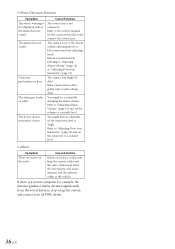
the cause. Connect the reverse signal line while referring to the owner's manual of the connected product. Connect the video connection cable to the camera input while referring to the owner's manual of the connected product. The rear camera image does not display, and the calibration mode appears. The control unit SETUP switch might be difficult to read . Turn the ignition key to OFF and then set to OFF. The camera image is dirty, wipe the lens...
the cause. Connect the reverse signal line while referring to the owner's manual of the connected product. Connect the video connection cable to the camera input while referring to the owner's manual of the connected product. The rear camera image does not display, and the calibration mode appears. The control unit SETUP switch might be difficult to read . Turn the ignition key to OFF and then set to OFF. The camera image is dirty, wipe the lens...
Owners Manual
Page 38
... wire harness, the radio antenna, and the antenna cables of the vehicle. If there are noises on the radio, keep the camera cables and the video cables away from the actual distance, stop using this system and contact your ALPINE dealer. 36-EN You might be dirty. • Object Detection Function Symptom The object warning is not connected. Refer to "Adjusting Alarm Volume" (page 16) and set...
... wire harness, the radio antenna, and the antenna cables of the vehicle. If there are noises on the radio, keep the camera cables and the video cables away from the actual distance, stop using this system and contact your ALPINE dealer. 36-EN You might be dirty. • Object Detection Function Symptom The object warning is not connected. Refer to "Adjusting Alarm Volume" (page 16) and set...


