Aspire X1200 / X3200 Service Guide
Page 7
... 32 Main Unit Disassembly 33 External Modules Disassembly Flowchart 33 Removing the Side Panel 34 Removing the Font Bezel 35 Removing the Heat Sink Fan Assembly 36 Removing the Processor 38 Removing the Optical Drive 40 Removing the Hard Disk Drive 42 Removing the Power Supply 46 Removing the ... Diagram and Board Layout 69 System Block Diagram 69 Board Layout 70 Mainboard 70 System Jumpers 71 FRU (Field Replaceable Unit) List 73 Aspire ASX1200/ ASX3200 Exploded Diagram 74 Aspire ASX1200/ ASX3200 FRU List (81.3V001.010G) 75 Technical Specifications 83 vii
... 32 Main Unit Disassembly 33 External Modules Disassembly Flowchart 33 Removing the Side Panel 34 Removing the Font Bezel 35 Removing the Heat Sink Fan Assembly 36 Removing the Processor 38 Removing the Optical Drive 40 Removing the Hard Disk Drive 42 Removing the Power Supply 46 Removing the ... Diagram and Board Layout 69 System Block Diagram 69 Board Layout 70 Mainboard 70 System Jumpers 71 FRU (Field Replaceable Unit) List 73 Aspire ASX1200/ ASX3200 Exploded Diagram 74 Aspire ASX1200/ ASX3200 FRU List (81.3V001.010G) 75 Technical Specifications 83 vii
Aspire X1200 / X3200 Service Guide
Page 13
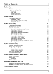
Internal Components A B C D E Item A B C D E Component Expansion card Mainboard Optical drive Heat sink fan assembly Power supply Chapter 1 5
Internal Components A B C D E Item A B C D E Component Expansion card Mainboard Optical drive Heat sink fan assembly Power supply Chapter 1 5
Aspire X1200 / X3200 Service Guide
Page 32
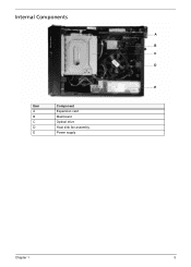
Set the CPU shutdown temperature. Option Enabled Disabled Disabled 60 ° C/140 ° F 65 ° C/149 ° F 70 ° C/158 ° F 24 Chapter 2 PC Health Status Parameter Smart FAN Control Shutdown Temperature Description Enables or disables the smart system fan control function.
Set the CPU shutdown temperature. Option Enabled Disabled Disabled 60 ° C/140 ° F 65 ° C/149 ° F 70 ° C/158 ° F 24 Chapter 2 PC Health Status Parameter Smart FAN Control Shutdown Temperature Description Enables or disables the smart system fan control function.
Aspire X1200 / X3200 Service Guide
Page 41
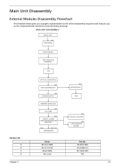
MAIN UNIT DISASSEMBLY MAIN UNIT Ax2 SIDE PANEL FRONT BEZEL HEAT SINK FAN ASSEMBLY CPU OPTICAL DISK DRIVE Ax1 HDD-ODD BRACKET Ax4 POWER SUPPLY Bx1 HDD MODULE HDD Screw List A B C D MEMORY MODULES Ax1 PCI CARD Bx2 FRONT I/O ...
MAIN UNIT DISASSEMBLY MAIN UNIT Ax2 SIDE PANEL FRONT BEZEL HEAT SINK FAN ASSEMBLY CPU OPTICAL DISK DRIVE Ax1 HDD-ODD BRACKET Ax4 POWER SUPPLY Bx1 HDD MODULE HDD Screw List A B C D MEMORY MODULES Ax1 PCI CARD Bx2 FRONT I/O ...
Aspire X1200 / X3200 Service Guide
Page 44
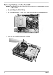
See "Removing the Side Panel" on the heat sink, in the order as shown below. 4. Use a long-nosed screwdriver to loosen the four screws on page 34. 2. See "Removing the Font Bezel" on . Lift the heat sink fan assembly away from the mainboard. 36 Chapter 3 NEVER touch the heat sink with any metal or with your hands. 1. Removing the Heat Sink Fan Assembly WARNING:The heat sink becomes very hot when the system is on page 35. 3.
See "Removing the Side Panel" on the heat sink, in the order as shown below. 4. Use a long-nosed screwdriver to loosen the four screws on page 34. 2. See "Removing the Font Bezel" on . Lift the heat sink fan assembly away from the mainboard. 36 Chapter 3 NEVER touch the heat sink with any metal or with your hands. 1. Removing the Heat Sink Fan Assembly WARNING:The heat sink becomes very hot when the system is on page 35. 3.
Aspire X1200 / X3200 Service Guide
Page 45
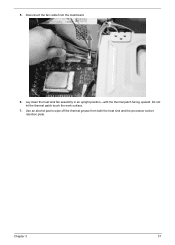
Disconnect the fan cable from both the heat sink and the processor socket retention plate. Chapter 3 37 Use an alcohol pad to wipe off the thermal grease from the mainboard. 6. Lay down the heat sink fan assembly in an upright position-with the thermal patch facing upward. Do not let the thermal patch touch the work surface. 7. 5.
Disconnect the fan cable from both the heat sink and the processor socket retention plate. Chapter 3 37 Use an alcohol pad to wipe off the thermal grease from the mainboard. 6. Lay down the heat sink fan assembly in an upright position-with the thermal patch facing upward. Do not let the thermal patch touch the work surface. 7. 5.
Aspire X1200 / X3200 Service Guide
Page 46
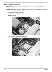
Removing the Processor IMPORTANT:Before removing a processor from the mainboard, make sure to the fully open, upright position. 38 Chapter 3 See "Removing the Font Bezel" on page 34. 2. Release the load lever. 5. Pull the load lever to create a backup file of all important data. Allow it to cool off first before handling. 1. See "Removing the Side Panel" on page 35. 3. See "Removing the Heat Sink Fan Assembly" on . WARNING:The processor becomes very hot when the system is on page 36. 4.
Removing the Processor IMPORTANT:Before removing a processor from the mainboard, make sure to the fully open, upright position. 38 Chapter 3 See "Removing the Font Bezel" on page 34. 2. Release the load lever. 5. Pull the load lever to create a backup file of all important data. Allow it to cool off first before handling. 1. See "Removing the Side Panel" on page 35. 3. See "Removing the Heat Sink Fan Assembly" on . WARNING:The processor becomes very hot when the system is on page 36. 4.
Aspire X1200 / X3200 Service Guide
Page 48
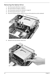
Removing the Optical Drive 1. See "Removing the Heat Sink Fan Assembly" on page 38. 5. Disconnect the data and power cables from the rear of the optical drive and the mainboard. 6. See "Removing the Processor" on page 36. 4. See "Removing the Font Bezel" on page 34. 2. See "Removing the Side Panel" on page 35. 3. Release the drive bay retention release lever. 40 Chapter 3
Removing the Optical Drive 1. See "Removing the Heat Sink Fan Assembly" on page 38. 5. Disconnect the data and power cables from the rear of the optical drive and the mainboard. 6. See "Removing the Processor" on page 36. 4. See "Removing the Font Bezel" on page 34. 2. See "Removing the Side Panel" on page 35. 3. Release the drive bay retention release lever. 40 Chapter 3
Aspire X1200 / X3200 Service Guide
Page 50
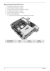
Remove the screw (A) that secures the HDD bracket to 6.5 kgf-cm Part No. 86.00J07.B60 42 Chapter 3 See "Removing the Heat Sink Fan Assembly" on page 38. 5. See "Removing the Processor" on page 36. 4. a. Screw (Quantity) #6-32 L5 BZN (1) Color Black Torque 5.5 to the chassis. See "Removing the Font Bezel" on page 34. 2. See "Removing the Side Panel" on page 35. 3. See "Removing the Optical Drive" on page 40. 6. Removing the Hard Disk Drive 1. Remove the HDD-ODD bracket.
Remove the screw (A) that secures the HDD bracket to 6.5 kgf-cm Part No. 86.00J07.B60 42 Chapter 3 See "Removing the Heat Sink Fan Assembly" on page 38. 5. See "Removing the Processor" on page 36. 4. a. Screw (Quantity) #6-32 L5 BZN (1) Color Black Torque 5.5 to the chassis. See "Removing the Font Bezel" on page 34. 2. See "Removing the Side Panel" on page 35. 3. See "Removing the Optical Drive" on page 40. 6. Removing the Hard Disk Drive 1. Remove the HDD-ODD bracket.
Aspire X1200 / X3200 Service Guide
Page 54
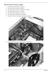
See "Removing the Optical Drive" on page 34. 2. See "Removing the Side Panel" on page 40. 6. See "Removing the Font Bezel" on page 38. 5. See "Removing the Processor" on page 35. 3. Disconnect the 24-pin power supply cable from the mainboard. 8. Disconnect the 8-pin power supply cable from the mainboard. 46 Chapter 3 See "Removing the Heat Sink Fan Assembly" on page 42. 7. See "Removing the Hard Disk Drive" on page 36. 4. Removing the Power Supply 1.
See "Removing the Optical Drive" on page 34. 2. See "Removing the Side Panel" on page 40. 6. See "Removing the Font Bezel" on page 38. 5. See "Removing the Processor" on page 35. 3. Disconnect the 24-pin power supply cable from the mainboard. 8. Disconnect the 8-pin power supply cable from the mainboard. 46 Chapter 3 See "Removing the Heat Sink Fan Assembly" on page 42. 7. See "Removing the Hard Disk Drive" on page 36. 4. Removing the Power Supply 1.
Aspire X1200 / X3200 Service Guide
Page 57
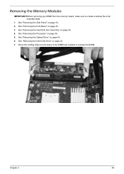
See "Removing the Side Panel" on page 42. 7. See "Removing the Hard Disk Drive" on page 34. 2. See "Removing the Processor" on page 36. 4. Press the holding clips on both sides of the DIMM slot outward to create a backup file of all important data. 1. Chapter 3 49 See "Removing the Heat Sink Fan Assembly" on page 38. 5. See "Removing the Optical Drive" on page 35. 3. See "Removing the Font Bezel" on page 40. 6. Removing the Memory Modules IMPORTANT:Before removing any DIMM from the memory board, make sure to release the DIMM.
See "Removing the Side Panel" on page 42. 7. See "Removing the Hard Disk Drive" on page 34. 2. See "Removing the Processor" on page 36. 4. Press the holding clips on both sides of the DIMM slot outward to create a backup file of all important data. 1. Chapter 3 49 See "Removing the Heat Sink Fan Assembly" on page 38. 5. See "Removing the Optical Drive" on page 35. 3. See "Removing the Font Bezel" on page 40. 6. Removing the Memory Modules IMPORTANT:Before removing any DIMM from the memory board, make sure to release the DIMM.
Aspire X1200 / X3200 Service Guide
Page 59
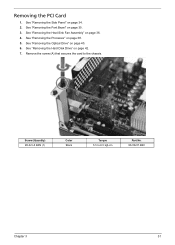
Remove the screw (A) that secures the card to 6.5 kgf-cm Part No. 86.00J07.B60 Chapter 3 51 See "Removing the Processor" on page 34. 2. See "Removing the Side Panel" on page 38. 5. See "Removing the Hard Disk Drive" on page 35. 3. Removing the PCI Card 1. See "Removing the Font Bezel" on page 42. 7. See "Removing the Heat Sink Fan Assembly" on page 40. 6. See "Removing the Optical Drive" on page 36. 4. Screw (Quantity) #6-32 L5 BZN (1) Color Black Torque 5.5 to the chassis.
Remove the screw (A) that secures the card to 6.5 kgf-cm Part No. 86.00J07.B60 Chapter 3 51 See "Removing the Processor" on page 34. 2. See "Removing the Side Panel" on page 38. 5. See "Removing the Hard Disk Drive" on page 35. 3. Removing the PCI Card 1. See "Removing the Font Bezel" on page 42. 7. See "Removing the Heat Sink Fan Assembly" on page 40. 6. See "Removing the Optical Drive" on page 36. 4. Screw (Quantity) #6-32 L5 BZN (1) Color Black Torque 5.5 to the chassis.
Aspire X1200 / X3200 Service Guide
Page 61
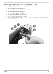
See "Removing the Heat Sink Fan Assembly" on page 38. 5. See "Removing the Processor" on page 36. 4. See "Removing the Memory Modules" on page 35. 3. Chapter 3 53 See "Removing the Font Bezel" on page 49. 8. Removing the Front I /O and card reader boards. See "Removing the Optical Drive" on page 42. 7. See "Removing the Hard Disk Drive" on page 40. 6. Disconnect one end of the three USB (1, 2, and 4), audio (2), and 1394 (5) cables from the rear of the I /O and Card Reader Boards 1. See "Removing the Side Panel" on page 34. 2.
See "Removing the Heat Sink Fan Assembly" on page 38. 5. See "Removing the Processor" on page 36. 4. See "Removing the Memory Modules" on page 35. 3. Chapter 3 53 See "Removing the Font Bezel" on page 49. 8. Removing the Front I /O and card reader boards. See "Removing the Optical Drive" on page 42. 7. See "Removing the Hard Disk Drive" on page 40. 6. Disconnect one end of the three USB (1, 2, and 4), audio (2), and 1394 (5) cables from the rear of the I /O and Card Reader Boards 1. See "Removing the Side Panel" on page 34. 2.
Aspire X1200 / X3200 Service Guide
Page 65
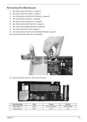
... Side Panel" on page 38. 5. See "Removing the Processor" on page 34. 2. See "Removing the Optical Drive" on page 36. 4. See "Removing the Heat Sink Fan Assembly" on page 40. 6. See "Removing the Hard Disk Drive" on page 51. 9. See "Removing the PCI Card" on page 42. 7. Remove the three screws...
... Side Panel" on page 38. 5. See "Removing the Processor" on page 34. 2. See "Removing the Optical Drive" on page 36. 4. See "Removing the Heat Sink Fan Assembly" on page 40. 6. See "Removing the Hard Disk Drive" on page 51. 9. See "Removing the PCI Card" on page 42. 7. Remove the three screws...
Aspire X1200 / X3200 Service Guide
Page 78
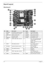
Board Layout Mainboard No Code Description No Code 1 CPUFAN1 Processor fan cable connector 13 JBIOS1 2 PWR2 24-pin ATX power connector 14 FIREH1 3 DIMM1 and 2 System memory slots 15 AUDIOF1 4 UI Processor socket 16 PCIEX16 5 DEBUGH1 ...Debug connector 17 PCIEX1 6 SATA2 SATA 2 data cable connector 18 7 LEDH1 8 SYSFAN1 9 USBF3 10 USBF2 11 SATA1 12 USBF1 LED cable connector 19 System fan cable connector 20 Front USB connectors 21 22 SATA 1 data cable connector 23 Front USB connector 24 PWR1 Description Clear CMOS jumper IEEE 1394 connector...
Board Layout Mainboard No Code Description No Code 1 CPUFAN1 Processor fan cable connector 13 JBIOS1 2 PWR2 24-pin ATX power connector 14 FIREH1 3 DIMM1 and 2 System memory slots 15 AUDIOF1 4 UI Processor socket 16 PCIEX16 5 DEBUGH1 ...Debug connector 17 PCIEX1 6 SATA2 SATA 2 data cable connector 18 7 LEDH1 8 SYSFAN1 9 USBF3 10 USBF2 11 SATA1 12 USBF1 LED cable connector 19 System fan cable connector 20 Front USB connectors 21 22 SATA 1 data cable connector 23 Front USB connector 24 PWR1 Description Clear CMOS jumper IEEE 1394 connector...
Aspire X1200 / X3200 Service Guide
Page 86
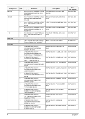
Component 640 GB 750 GB 1 TB Heat sink Keyboard QTY 1 1 1 1 1 Part Name HDD 640GB 3.5" 7200RPM SATA II WD WD6400AAKS-22A7B0 LF F/ W:01.03B01 HDD ...750GB SATA 8MB 7200 NCQ HDD WD 750GB SATA 8MB 7200 NCQ HDD HGST 1TB SATA 8MB 7200 NCQ Acer Part Number KH.64008.001 KH.75001.003 KH.75007.001 KH.75008.001 KH.01K07.001 1 CPU COOLER WITH... FAN LGA775 ASSY COOLER LGA775 ATX TMDC6 (TMD06 W/O FAN DUCT) HI.10800.012 1 KEYBOARD PS2 104KEY CHICONY KB-07593US2552V US2552V US BLAC KB PS2 KB-07593US2552V US BLAC...
Component 640 GB 750 GB 1 TB Heat sink Keyboard QTY 1 1 1 1 1 Part Name HDD 640GB 3.5" 7200RPM SATA II WD WD6400AAKS-22A7B0 LF F/ W:01.03B01 HDD ...750GB SATA 8MB 7200 NCQ HDD WD 750GB SATA 8MB 7200 NCQ HDD HGST 1TB SATA 8MB 7200 NCQ Acer Part Number KH.64008.001 KH.75001.003 KH.75007.001 KH.75008.001 KH.01K07.001 1 CPU COOLER WITH... FAN LGA775 ASSY COOLER LGA775 ATX TMDC6 (TMD06 W/O FAN DUCT) HI.10800.012 1 KEYBOARD PS2 104KEY CHICONY KB-07593US2552V US2552V US BLAC KB PS2 KB-07593US2552V US BLAC...


