
Veriton 9100 Service Guide
Page 7
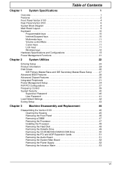
... Panel-Veriton 9100 4 Rear Panel-Veriton 9100 6 System Block Diagram 8 Main Board Layout 9 Keyboard 10 Programmable keys 10 Internet/Suspend keys 10 Multimedia keys 11 Volume control/Mute 11 Cursor keys 11 Lock keys 11 Windows keys 12 Hardware Specifications and Configurations 13 Power Management Functions 21 Chapter 2 System Utilities 22 Entering Setup 23 Product Information 24 Disk Drives 25 IDE Primary Master/Slave and IDE Secondary Master/Slave Setup . . . . .27 Advanced BIOS Features 28 Advanced Chipset Features 30 Integrated Peripherals 31 Power Management Setup...
... Panel-Veriton 9100 4 Rear Panel-Veriton 9100 6 System Block Diagram 8 Main Board Layout 9 Keyboard 10 Programmable keys 10 Internet/Suspend keys 10 Multimedia keys 11 Volume control/Mute 11 Cursor keys 11 Lock keys 11 Windows keys 12 Hardware Specifications and Configurations 13 Power Management Functions 21 Chapter 2 System Utilities 22 Entering Setup 23 Product Information 24 Disk Drives 25 IDE Primary Master/Slave and IDE Secondary Master/Slave Setup . . . . .27 Advanced BIOS Features 28 Advanced Chipset Features 30 Integrated Peripherals 31 Power Management Setup...
Veriton 9100 Service Guide
Page 11
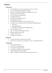
... LAN Controller (82801BA). ! 3.5-inch and 5.25-inch floppy disk drives. ! Four USB ports ( available on front and rear panels) ! Intel® Willamette processors, with remote wake-up function 2 Chapter 1 CPU SMM (System Management Mode), STOP clock control ! On-board PCI master enhanced local bus IDE (Embedded in , and Game/MIDI interface Connectivity ! Multiword DMA Mode 2 ! Software shutdown for 400 MHz. ! Power management features ! CD-ROM/DVD-ROM drive ! High capacity, Enhanced-IDE hard disk ! On-board DC-to 1.5GHz. ! Audio...
... LAN Controller (82801BA). ! 3.5-inch and 5.25-inch floppy disk drives. ! Four USB ports ( available on front and rear panels) ! Intel® Willamette processors, with remote wake-up function 2 Chapter 1 CPU SMM (System Management Mode), STOP clock control ! On-board PCI master enhanced local bus IDE (Embedded in , and Game/MIDI interface Connectivity ! Multiword DMA Mode 2 ! Software shutdown for 400 MHz. ! Power management features ! CD-ROM/DVD-ROM drive ! High capacity, Enhanced-IDE hard disk ! On-board DC-to 1.5GHz. ! Audio...
Veriton 9100 Service Guide
Page 22
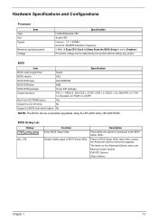
...be overwritten/upgraded using the AFLASH utility (AFLASH.EXE). BIOS Hotkey List Hotkey ++ Alt + F4 Function Enter BIOS Setup Utility Enable hidden page of BIOS Setup Utility Description Press while the system is set to Enabled.) Processor voltage can be detected by the system without setting any jumper. The items on the Advanced Options menu are: Memory/Cache Options PnP/PCI Options Chips Options Chapter 1 13 Hardware Specifications and Configurations Processor Type Slot Speed Item Minimum operating speed Voltage Specification Intel® Willamette CPU Socket 423 Internal...
...be overwritten/upgraded using the AFLASH utility (AFLASH.EXE). BIOS Hotkey List Hotkey ++ Alt + F4 Function Enter BIOS Setup Utility Enable hidden page of BIOS Setup Utility Description Press while the system is set to Enabled.) Processor voltage can be detected by the system without setting any jumper. The items on the Advanced Options menu are: Memory/Cache Options PnP/PCI Options Chips Options Chapter 1 13 Hardware Specifications and Configurations Processor Type Slot Speed Item Minimum operating speed Voltage Specification Intel® Willamette CPU Socket 423 Internal...

Veriton 9100 Service Guide
Page 24
... wavetable synthesizers and MIDI devices Integrated dual game port Meets PC 97/PC98 and WHQL specifications Yes 44.1 KHz Yes Supported On audio-I/O board (connects via CN8) Supported On audio-I/O board (connects via CN8) QFP64 IDE Interface Item IDE controller IDE controller resident bus Number of IDE channel Support IDE interface Support bootable CD-ROM Specification Embedded in Intel 82801BA ICH II PCI bus 2 on-board: 40-pin hard disk drive connector, E-IDE (up to PIO...
... wavetable synthesizers and MIDI devices Integrated dual game port Meets PC 97/PC98 and WHQL specifications Yes 44.1 KHz Yes Supported On audio-I/O board (connects via CN8) Supported On audio-I/O board (connects via CN8) QFP64 IDE Interface Item IDE controller IDE controller resident bus Number of IDE channel Support IDE interface Support bootable CD-ROM Specification Embedded in Intel 82801BA ICH II PCI bus 2 on-board: 40-pin hard disk drive connector, E-IDE (up to PIO...

Veriton 9100 Service Guide
Page 41
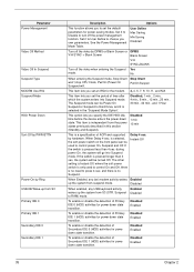
... USB controller USB Keyboard Support USB Mouse Support Init Display First AC97 Audio AC97 Mode Onboard/ CNR LAN Selection IDE HDD Block Mode Power On function Onboard FDD Controller Onboard Serial Port 1 Onboard Serial Port 2 UART Mode Select Description These items allow you enable or disable the USB mouse driver within the onboard BIOS. Options Auto Disabled This item is the initial display card. The mouse driver simulates legacy mouse command and lets you use a USB mouse during POST or after boot if you don't have a USB driver in the operating...
... USB controller USB Keyboard Support USB Mouse Support Init Display First AC97 Audio AC97 Mode Onboard/ CNR LAN Selection IDE HDD Block Mode Power On function Onboard FDD Controller Onboard Serial Port 1 Onboard Serial Port 2 UART Mode Select Description These items allow you enable or disable the USB mouse driver within the onboard BIOS. Options Auto Disabled This item is the initial display card. The mouse driver simulates legacy mouse command and lets you use a USB mouse during POST or after boot if you don't have a USB driver in the operating...
Veriton 9100 Service Guide
Page 44
... Enabled, any USB keyboard activity wakes up the system from S3 (STR, Suspend to RAM) mode. Enabled Disabled To enable or disable the detection of Primary IDE 0 (HDD) activities for power down state transition. Disabled Enabled To enable or disable the detection of Secondary IDE 1 (HDD) activities for power-saving modes. Set it to Disable to turn off the video when entering the Suspend Yes mode. is selected, the soft power switch on the front panel can be Power...
... Enabled, any USB keyboard activity wakes up the system from S3 (STR, Suspend to RAM) mode. Enabled Disabled To enable or disable the detection of Primary IDE 0 (HDD) activities for power down state transition. Disabled Enabled To enable or disable the detection of Secondary IDE 1 (HDD) activities for power-saving modes. Set it to Disable to turn off the video when entering the Suspend Yes mode. is selected, the soft power switch on the front panel can be Power...

Veriton 9100 Service Guide
Page 46
...) Manual If your ISA card is PCI/ISA PnP. The default is not PnP compatible and requires a special IRQ to support its function, set the selected IRQ to enable the auto-configuration function. Take note that the OS cannot boot. Parameter Reset Configuration Dat Resources Controlled By IRQ Resources IRQ 3 (COM2) IRQ 4 (COM1) IRQ 5 (Network/Sound or Others IRQ 7 (Printer or Others) IRQ 9 (Video or...
...) Manual If your ISA card is PCI/ISA PnP. The default is not PnP compatible and requires a special IRQ to support its function, set the selected IRQ to enable the auto-configuration function. Take note that the OS cannot boot. Parameter Reset Configuration Dat Resources Controlled By IRQ Resources IRQ 3 (COM2) IRQ 4 (COM1) IRQ 5 (Network/Sound or Others IRQ 7 (Printer or Others) IRQ 9 (Video or...
Veriton 9100 Service Guide
Page 54
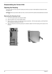
... . Remove the four screws of the unit. 4. Do the same for the left panel. 45 Chapter 3 CAUTION: Before you proceed, make sure that you will need to install additional components inside the system unit. Removing the Housing Cover 1. Disassembling the Veriton 9100 Opening the Housing This section tells you how to open the housing cover when you need them when replacing the right panel of the right panel using...
... . Remove the four screws of the unit. 4. Do the same for the left panel. 45 Chapter 3 CAUTION: Before you proceed, make sure that you will need to install additional components inside the system unit. Removing the Housing Cover 1. Disassembling the Veriton 9100 Opening the Housing This section tells you how to open the housing cover when you need them when replacing the right panel of the right panel using...

Veriton 9100 Service Guide
Page 63
Power-On Self-Test (POST) ! Index of Error Symptoms ! Index of Error Codes and Error Beeps ! Undetermined Problems Chapter 4 Chapter 4 54 Troubleshooting This chapter provides troubleshooting information for the Veriton 9100: ! Index of Error Messages !
Power-On Self-Test (POST) ! Index of Error Symptoms ! Index of Error Codes and Error Beeps ! Undetermined Problems Chapter 4 Chapter 4 54 Troubleshooting This chapter provides troubleshooting information for the Veriton 9100: ! Index of Error Messages !
Veriton 9100 Service Guide
Page 64
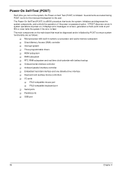
...-processor and cache memory subsystem ! RAM subsystem ! PS/2-compatible keyboard port ! USB port 55 Chapter 4 PS/2-compatible mouse port ! Serial ports ! Several items are as follows: ! The main components on the main board that boots the system, initializes and diagnoses the system components, and controls the operation of the power-on screen, generates a check point code at port 80h or even halts the system if the error is initiated. Embedded hard disk...
...-processor and cache memory subsystem ! RAM subsystem ! PS/2-compatible keyboard port ! USB port 55 Chapter 4 PS/2-compatible mouse port ! Serial ports ! Several items are as follows: ! The main components on the main board that boots the system, initializes and diagnoses the system components, and controls the operation of the power-on screen, generates a check point code at port 80h or even halts the system if the error is initiated. Embedded hard disk...
Veriton 9100 Service Guide
Page 65
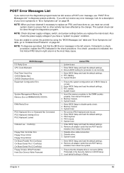
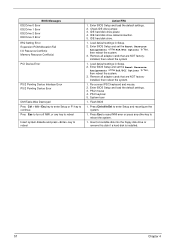
... cable/connection. 2. Remove all adapter cards that are unable to correct the problem by the change. Chapter 4 56 This system check can be done through the diagnostics program. Conflict(s) Floppy Disk Controller Erro Floppy Drive A Error Floppy Drive B Error On Board Parallel Port Conflict(s) On Board Serial Port 1 Conflict(s) On Board Serial Port 2 Conflict(s) Floppy Drive(s) Write Protected Hard Disk Drive(s) Write Protected Action/FRU 1. Enter BIOS Setup and load the default settings. 2. System Board. 1. Memory module 3. Re-connect PS/2 keyboard and mouse. 2. RTC battery...
... cable/connection. 2. Remove all adapter cards that are unable to correct the problem by the change. Chapter 4 56 This system check can be done through the diagnostics program. Conflict(s) Floppy Disk Controller Erro Floppy Drive A Error Floppy Drive B Error On Board Parallel Port Conflict(s) On Board Serial Port 1 Conflict(s) On Board Serial Port 2 Conflict(s) Floppy Drive(s) Write Protected Hard Disk Drive(s) Write Protected Action/FRU 1. Enter BIOS Setup and load the default settings. 2. System Board. 1. Memory module 3. Re-connect PS/2 keyboard and mouse. 2. RTC battery...
Veriton 9100 Service Guide
Page 66
... disk drive or remove this disk if a hard disk is installed. 57 Chapter 4 Load default settings in Setup. 2. Re-connect PS/2 keyboard and mouse. 2. IDE hard disk drive power. 4. Enter BIOS Setup and load the default settings. 3. Flash BIOS 1. BIOS Messages IDE Drive 0 Error IDE Drive 1 Error IDE Drive 2 Error IDE Drive 3 Error IRQ Setting Error Expansion ROM Allocation Fail I/O Resource Conflict(s Memory Resource Conflict(s) PCI Device Error PS/2 Pointing Device Interface Error PS/2 Pointing Device Error DMI Table Was Destroyed Pres Ctrl + Alt + Esc key to enter Setup or F1 key...
... disk drive or remove this disk if a hard disk is installed. 57 Chapter 4 Load default settings in Setup. 2. Re-connect PS/2 keyboard and mouse. 2. IDE hard disk drive power. 4. Enter BIOS Setup and load the default settings. 3. Flash BIOS 1. BIOS Messages IDE Drive 0 Error IDE Drive 1 Error IDE Drive 2 Error IDE Drive 3 Error IRQ Setting Error Expansion ROM Allocation Fail I/O Resource Conflict(s Memory Resource Conflict(s) PCI Device Error PS/2 Pointing Device Interface Error PS/2 Pointing Device Error DMI Table Was Destroyed Pres Ctrl + Alt + Esc key to enter Setup or F1 key...

Veriton 9100 Service Guide
Page 67
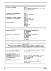
... power supply fan runs. 1. Diskette/IDE drive connection/cables 2. See "Undetermined Problems". 4. Diskette drive connection/cable 4. Ensure the diskette drive is not set in power saving mode. Diskette drive 5. Its reading should be +12Vdc. 3. Enter BIOS Setup and load default settings. Blinking cursor only; Diskette drive connection/cable 4. Error Symptom Action/FRU Processor / Processor Fan NOTE: Normally, the processor fan should be operative, and the processor clock setting should be exactly set it to see the potential cause of processor fa connector...
... power supply fan runs. 1. Diskette/IDE drive connection/cables 2. See "Undetermined Problems". 4. Diskette drive connection/cable 4. Ensure the diskette drive is not set in power saving mode. Diskette drive 5. Its reading should be +12Vdc. 3. Enter BIOS Setup and load default settings. Blinking cursor only; Diskette drive connection/cable 4. Error Symptom Action/FRU Processor / Processor Fan NOTE: Normally, the processor fan should be operative, and the processor clock setting should be exactly set it to see the potential cause of processor fa connector...
Veriton 9100 Service Guide
Page 68
... operates normally. 1. Diskette 2. Diskette drive connection/cable 3. System boar Hard Disk Drive NOTE: Ensure hard disk drive is configured correctly in BIOS Setup, cable/jumper are set correctly and its eject button is unable to light, but works normally. 1. Hard disk drive. 4. CD/DVD-ROM Drive NOTE: Ensure CD/DVD-ROM drive is clean before diagnosing any CD/DVD-ROM drive problems. CD/DVD-ROM drive LED doesn't come on it . CD/DVD-ROM drive CD/DVD-ROM drive LED flashes for more than 2 minutes when reading data. 1. Software asks to unload the disk. 2. CD/DVD-ROM...
... operates normally. 1. Diskette 2. Diskette drive connection/cable 3. System boar Hard Disk Drive NOTE: Ensure hard disk drive is configured correctly in BIOS Setup, cable/jumper are set correctly and its eject button is unable to light, but works normally. 1. Hard disk drive. 4. CD/DVD-ROM Drive NOTE: Ensure CD/DVD-ROM drive is clean before diagnosing any CD/DVD-ROM drive problems. CD/DVD-ROM drive LED doesn't come on it . CD/DVD-ROM drive CD/DVD-ROM drive LED flashes for more than 2 minutes when reading data. 1. Software asks to unload the disk. 2. CD/DVD-ROM...

Veriton 9100 Service Guide
Page 69
...-time clock is connected properly. 4. CD/DVD-ROM drive. Real-Time Clock 1. Speaker power/connection/cable. Ensure the modem card is set correctly. 2. Video adapter card 4. Monitor 3. Turn up system from modem adapter card to system board is inaccurate. "Monitor". 2. Modem ring cannot wake up the sound volume. 3. Video adapter failed. Incorrect colors No high intensity Missing, broken, or incorrect characters Blank monitor(dark) Blank monitor(bright) Distorted image Unreadable monitor Other monitor problems Display changing colors. Display problem not listed above (including...
...-time clock is connected properly. 4. CD/DVD-ROM drive. Real-Time Clock 1. Speaker power/connection/cable. Ensure the modem card is set correctly. 2. Video adapter card 4. Monitor 3. Turn up system from modem adapter card to system board is inaccurate. "Monitor". 2. Modem ring cannot wake up the sound volume. 3. Video adapter failed. Incorrect colors No high intensity Missing, broken, or incorrect characters Blank monitor(dark) Blank monitor(bright) Distorted image Unreadable monitor Other monitor problems Display changing colors. Display problem not listed above (including...

Veriton 9100 Service Guide
Page 70
... BIOS Setup. 2. Executing software shutdown from electrical outlet can turn on keyboard do not work. 1. No system power, or power supply fan is properly installed. Ensure the printer driver is not running. 1. System Board Other Problems Any other problems. 1. System board. Make sure that the LPT# or COM# you test is not set to Suspend. 2. Printer. 3. Printer cable. 4. Reload software from Recovery CD. Error Symptom Action/FRU Parallel/Serial Ports Execute "Load BIOS Default Settings" in BIOS Setup to the printer service manual...
... BIOS Setup. 2. Executing software shutdown from electrical outlet can turn on keyboard do not work. 1. No system power, or power supply fan is properly installed. Ensure the printer driver is not running. 1. System Board Other Problems Any other problems. 1. System board. Make sure that the LPT# or COM# you test is not set to Suspend. 2. Printer. 3. Printer cable. 4. Reload software from Recovery CD. Error Symptom Action/FRU Parallel/Serial Ports Execute "Load BIOS Default Settings" in BIOS Setup to the printer service manual...
Veriton 9100 Service Guide
Page 71
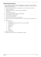
.... 3. Check all cables and connectors for proper installation. 9. External devices ! Diskette drive ! Perform the following checks, one by one at a time: 10. If the jumpers, switches and voltage settings are correct continue with this check: 1. Processor ! Chapter 4 62 Check all adapter card jumper positions. 7. System board 11. Undetermined Problems If an error message is listed in setup. 5. Check all system board jumper positions and switch settings. 6. Non-Acer devices ! Power on page 56. Hard disk drive ! If you...
.... 3. Check all cables and connectors for proper installation. 9. External devices ! Diskette drive ! Perform the following checks, one by one at a time: 10. If the jumpers, switches and voltage settings are correct continue with this check: 1. Processor ! Chapter 4 62 Check all adapter card jumper positions. 7. System board 11. Undetermined Problems If an error message is listed in setup. 5. Check all system board jumper positions and switch settings. 6. Non-Acer devices ! Power on page 56. Hard disk drive ! If you...
Veriton 9100 Service Guide
Page 93
... level 28 BIOS Setup 27 Entering Setup 28 Setup Utility 28 BIOS Utility Disk Drives 30 Exiting Setup 48 Load Default Settings 47 Power Management 39 Product Information 29 System Security 45 Block Diagram 13 C Cache Memory 19 size 19 speed 19 CD-ROM Drive removing 55 Chipsets 24 CMOS Setup 27 CompatibilityTest 83 Connectors 69 Description 70 description 70 controllers 24 audio 20 serial port 21 CPU removing 52, 53 CPU upgrade removing 52, 53 Index Index Current 25 D Device Standby Mode 26 Disk Drives 30...
... level 28 BIOS Setup 27 Entering Setup 28 Setup Utility 28 BIOS Utility Disk Drives 30 Exiting Setup 48 Load Default Settings 47 Power Management 39 Product Information 29 System Security 45 Block Diagram 13 C Cache Memory 19 size 19 speed 19 CD-ROM Drive removing 55 Chipsets 24 CMOS Setup 27 CompatibilityTest 83 Connectors 69 Description 70 description 70 controllers 24 audio 20 serial port 21 CPU removing 52, 53 CPU upgrade removing 52, 53 Index Index Current 25 D Device Standby Mode 26 Disk Drives 30...
Veriton 9100 Service Guide
Page 94
... keys 16 windows-keys 17 L Load Default Settings 47 M Machine Disassembly 49 cover 50 Housing Cover 50 Main board 69 removing 57 Main Board Layout 14 Mechanical Specifications 24 Memory removing 52 size 19 system 19 Memory Address Map 22 Model Definition 81 Modem 21 data 21 fax 21 voice 21 Motherboard removing 57 MPU-401 20 85 N Network port 11 O Online Support Information 87 Overview 6 P Parallel Port 21 Parallel/printer port 11 Password setting 45 PCI removing 56 PCI...
... keys 16 windows-keys 17 L Load Default Settings 47 M Machine Disassembly 49 cover 50 Housing Cover 50 Main board 69 removing 57 Main Board Layout 14 Mechanical Specifications 24 Memory removing 52 size 19 system 19 Memory Address Map 22 Model Definition 81 Modem 21 data 21 fax 21 voice 21 Motherboard removing 57 MPU-401 20 85 N Network port 11 O Online Support Information 87 Overview 6 P Parallel Port 21 Parallel/printer port 11 Password setting 45 PCI removing 56 PCI...

Veriton 9100 Service Guide
Page 95
... memory 19 Socket 370 18 Suspend Mode 26 Switching Power Supply 102W 25 Symptoms List 63 Audio 65 CD/DVD-ROM Drive 64 Diskette Drive 63 Keyboard 66 Memory 63 Modem 65 Monitor 65 Other 66 Parallel Port 66 Power Supply 66 Processor / Processor Fan 63 Real-Time Clock 65 Serial Port 66 System Board 63 Video 65 System 27 System Board removing 57 System Memory 52 System Specifications 6 design 8 Features 7 System Utilities 27 Disk Drives 30 Exiting Setup 48 Load Default Settings 47 Power Management...
... memory 19 Socket 370 18 Suspend Mode 26 Switching Power Supply 102W 25 Symptoms List 63 Audio 65 CD/DVD-ROM Drive 64 Diskette Drive 63 Keyboard 66 Memory 63 Modem 65 Monitor 65 Other 66 Parallel Port 66 Power Supply 66 Processor / Processor Fan 63 Real-Time Clock 65 Serial Port 66 System Board 63 Video 65 System 27 System Board removing 57 System Memory 52 System Specifications 6 design 8 Features 7 System Utilities 27 Disk Drives 30 Exiting Setup 48 Load Default Settings 47 Power Management...


