
TravelMate 4070 Service Guide
Page 57
... Replacement This chapter contains step-by-step procedures on how to avoid mismatch when putting back the components. To disassemble the computer, you need the following tools: T Wrist grounding strap and conductive mat for preventing electrostatic discharge T Flat-bladed screw driver T... screw driver T Tweezers T Plastic Flat-bladed screw driver T Hexed Screw Driver NOTE: The screws for maintenance and troubleshooting. During the disassembly process, group the screws with the corresponding components to disassemble the notebook computer for the different components vary in size.
... Replacement This chapter contains step-by-step procedures on how to avoid mismatch when putting back the components. To disassemble the computer, you need the following tools: T Wrist grounding strap and conductive mat for preventing electrostatic discharge T Flat-bladed screw driver T... screw driver T Tweezers T Plastic Flat-bladed screw driver T Hexed Screw Driver NOTE: The screws for maintenance and troubleshooting. During the disassembly process, group the screws with the corresponding components to disassemble the notebook computer for the different components vary in size.

TravelMate 4070 Service Guide
Page 58
General Information Before You Begin Before proceeding with the disassembly procedure, make sure that you disconnect different FFC/FPC/connectors. 53 Chapter 3 Unplug the AC adapter and all peripherals. 2. NOTE: Aspire 9100 series product uses mylar or tape to fasten the FFC/FPC/connectors/cable, you may need to the system and all power and signal cables from the system . Turn off the power to tear the tape or mylar before you do the following: 1.
General Information Before You Begin Before proceeding with the disassembly procedure, make sure that you disconnect different FFC/FPC/connectors. 53 Chapter 3 Unplug the AC adapter and all peripherals. 2. NOTE: Aspire 9100 series product uses mylar or tape to fasten the FFC/FPC/connectors/cable, you may need to the system and all power and signal cables from the system . Turn off the power to tear the tape or mylar before you do the following: 1.
TravelMate 4070 Service Guide
Page 59
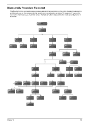
... representation on the components that order. For example, if you want to remove the main board, you on the entire disassembly sequence and instructs you must first remove the keyboard, then disassemble the inside assembly frame in that need to be removed during servicing. Start Battery HDD Module *2 HDD HDD Holder *2 Dimm...
... representation on the components that order. For example, if you want to remove the main board, you on the entire disassembly sequence and instructs you must first remove the keyboard, then disassemble the inside assembly frame in that need to be removed during servicing. Start Battery HDD Module *2 HDD HDD Holder *2 Dimm...

TravelMate 4070 Service Guide
Page 62
Removing the Hard Disc Drive Module 1. Then remove the HDD cover. 4. Remove two screw securing the HDD bracket. 2. Take out the HDD from the HDD bracket. 57 Chapter 3 Remove the HDD module. See "Removing the Battery" on the other side. 3. Disassembling the Hard Disc Drive Module 1. Remove the other two screw on page 56. 2. Remove the screw securing the hard disk drive (HDD) cover. 3. Pull the HDD module backwards as shown. 5.
Removing the Hard Disc Drive Module 1. Then remove the HDD cover. 4. Remove two screw securing the HDD bracket. 2. Take out the HDD from the HDD bracket. 57 Chapter 3 Remove the HDD module. See "Removing the Battery" on the other side. 3. Disassembling the Hard Disc Drive Module 1. Remove the other two screw on page 56. 2. Remove the screw securing the hard disk drive (HDD) cover. 3. Pull the HDD module backwards as shown. 5.
TravelMate 4070 Service Guide
Page 63
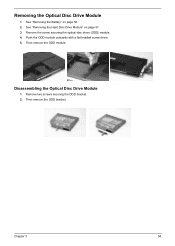
Remove the screw securing the optical disc drove (ODD) module. 4. Disassembling the Optical Disc Drive Module 1. See "Removing the Hard Disc Drive Module" on page 56. 2. Then remove the ODD bracket. Then remove the ODD module. Remove two screws securing the ODD bracket. 2. Push the ODD module outwards with a flat headed screw driver. 5. Chapter 3 58 Removing the Optical Disc Drive Module 1. See "Removing the Battery" on page 57. 3.
Remove the screw securing the optical disc drove (ODD) module. 4. Disassembling the Optical Disc Drive Module 1. See "Removing the Hard Disc Drive Module" on page 56. 2. Then remove the ODD bracket. Then remove the ODD module. Remove two screws securing the ODD bracket. 2. Push the ODD module outwards with a flat headed screw driver. 5. Chapter 3 58 Removing the Optical Disc Drive Module 1. See "Removing the Battery" on page 57. 3.

TravelMate 4070 Service Guide
Page 68
..., then remove the left bracket. 63 Chapter 3 See "Removing the LCD Module" on page 60. 5. Detach the two rubber pads and the two screw pads. 8. Disassembling the LCD Module Removing the LCD Bezel 1. Disconnect the LCD inverter cable. 13. See "Removing the Wireless LAN Card" on page 56. 2. Remove the four...
..., then remove the left bracket. 63 Chapter 3 See "Removing the LCD Module" on page 60. 5. Detach the two rubber pads and the two screw pads. 8. Disassembling the LCD Module Removing the LCD Bezel 1. Disconnect the LCD inverter cable. 13. See "Removing the Wireless LAN Card" on page 56. 2. Remove the four...

TravelMate 4070 Service Guide
Page 70
... off the tape holding the power board cable then remove the power board. 65 Chapter 3 See "Removing the Hard Disc Drive Module" on page 57. 3. Disassembling the Main Unit Removing the Upper Case Assembly 1. See "Removing the Battery" on page 56.. 2.
... off the tape holding the power board cable then remove the power board. 65 Chapter 3 See "Removing the Hard Disc Drive Module" on page 57. 3. Disassembling the Main Unit Removing the Upper Case Assembly 1. See "Removing the Battery" on page 56.. 2.

TravelMate 4070 User's Guide
Page 68
...and will often require extensive work by the operating instructions, since improper adjustment of them away from the wall outlet before serving or disassembling this unit. d If the product does not operate normally when the operating instructions are covered by a qualified technician to restore ...the product to dangerous voltage points or other risks. Do not disassemble or dispose of other than a cordless type) during an electrical storm. Refer all telephone lines from children and dispose of used...
...and will often require extensive work by the operating instructions, since improper adjustment of them away from the wall outlet before serving or disassembling this unit. d If the product does not operate normally when the operating instructions are covered by a qualified technician to restore ...the product to dangerous voltage points or other risks. Do not disassemble or dispose of other than a cordless type) during an electrical storm. Refer all telephone lines from children and dispose of used...

TravelMate 4070 User's Guide
Page 69
... technology that is protected by Macrovision. and 6,516,132. Nevertheless, some pixels may occasionally misfire or appear as black or red dots. Reverse engineering or disassembly is located on the recorded image and does not constitute a malfunction. VARNING: LASERSTRÅLNING NÅR DENNA DEL ÅR ÖPPNAD ÅLÅ TUIJOTA SÅ...
... technology that is protected by Macrovision. and 6,516,132. Nevertheless, some pixels may occasionally misfire or appear as black or red dots. Reverse engineering or disassembly is located on the recorded image and does not constitute a malfunction. VARNING: LASERSTRÅLNING NÅR DENNA DEL ÅR ÖPPNAD ÅLÅ TUIJOTA SÅ...


