
TravelMate 4070 Service Guide
Page 10
... 17 CN17 RJ45 & RJ11 Connector 19 U11 North Bridge 21 CN20 USB Connector 23 U19 BIOS ROM 25 CN22 RTC Battery 27 U1 LAN Chipset RTL8100CL Chapter 1 2 CN1 LCD Connector 4 CN3 Modem Connector 6 CN4 Bluetooth Module Connector 8 CN6 Internal Microphone Connector 10 U4 PCMCIA Connector 12 ...
... 17 CN17 RJ45 & RJ11 Connector 19 U11 North Bridge 21 CN20 USB Connector 23 U19 BIOS ROM 25 CN22 RTC Battery 27 U1 LAN Chipset RTL8100CL Chapter 1 2 CN1 LCD Connector 4 CN3 Modem Connector 6 CN4 Bluetooth Module Connector 8 CN6 Internal Microphone Connector 10 U4 PCMCIA Connector 12 ...
TravelMate 4070 Service Guide
Page 13
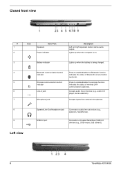
Accepts inputs from external microphones. Indicates the status of Bluetooth communication (optional). Left view 8 TravelMate 4070/4080 Speaker/Line-Out/Headphone jack Connects to Universal Serial Bus (USB) 2.0 devices (e.g., USB ... Icon Speakers Item/ Port Power indicator Description Left and right speakers deliver stereo audio output. Lights up when the computer is on. 3 Battery indicator Lights up when the battery is being charged. 4 # Ite5m 6 7 # Item 8 9 Bluetooth communication button/ indicator DesWcriirpetleiosns communication button/ indicator Line-in devices...
Accepts inputs from external microphones. Indicates the status of Bluetooth communication (optional). Left view 8 TravelMate 4070/4080 Speaker/Line-Out/Headphone jack Connects to Universal Serial Bus (USB) 2.0 devices (e.g., USB ... Icon Speakers Item/ Port Power indicator Description Left and right speakers deliver stereo audio output. Lights up when the computer is on. 3 Battery indicator Lights up when the battery is being charged. 4 # Ite5m 6 7 # Item 8 9 Bluetooth communication button/ indicator DesWcriirpetleiosns communication button/ indicator Line-in devices...
TravelMate 4070 Service Guide
Page 15
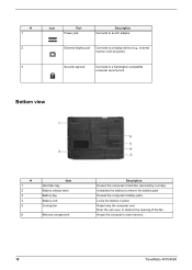
... keep the computer cool. Bottom view # 1 2 3 4 5 6 Item Hard disc bay Battery release latch Battery bay Battery lock Cooling fan Memory comparment Description Houses the computer's hard disc (secured by a screw). Houses the computer's battery pack. House the computer's main memory. 10 TravelMate 4070/4080 Locks the battery in place. # 1 2 3 Icon Port Power jack Description Connects to a display...
... keep the computer cool. Bottom view # 1 2 3 4 5 6 Item Hard disc bay Battery release latch Battery bay Battery lock Cooling fan Memory comparment Description Houses the computer's hard disc (secured by a screw). Houses the computer's battery pack. House the computer's main memory. 10 TravelMate 4070/4080 Locks the battery in place. # 1 2 3 Icon Port Power jack Description Connects to a display...

TravelMate 4070 Service Guide
Page 16
...Indicates the status of Bluetooth communication. NOTE: 2. Chapter 1 11 Lights when the computer is activated. Lights when Numeric Lock is active. Battery Lights when the battery is charging. Fully charged: light shows green when in AC mode. Indicators The computer has three easy-to-read status icons on the ...upper-right above the keyboard, and four on . Charging: the light shows amber when the battery is being charged. Icon Function Description Icon Function Caps Lock Num Lock Description Lights when Caps Lock is on the front panel.
...Indicates the status of Bluetooth communication. NOTE: 2. Chapter 1 11 Lights when the computer is activated. Lights when Numeric Lock is active. Battery Lights when the battery is charging. Fully charged: light shows green when in AC mode. Indicators The computer has three easy-to-read status icons on the ...upper-right above the keyboard, and four on . Charging: the light shows amber when the battery is being charged. Icon Function Description Icon Function Caps Lock Num Lock Description Lights when Caps Lock is on the front panel.
TravelMate 4070 Service Guide
Page 23
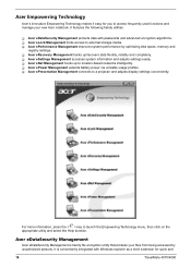
... with passwords and advanced encryption algorithms. T Acer eLock Management limits access to external storage media. T Acer eSettings Management accesses system information and adjusts settings easily. T Acer ePower Management extends battery power via versatile usage profiles. Acer Empowering Technology Acer's innovative Empowering Technology makes it easy for quick and 18 TravelMate 4070/4080 T Acer ePerformance Management improves system performance by...
... with passwords and advanced encryption algorithms. T Acer eLock Management limits access to external storage media. T Acer eSettings Management accesses system information and adjusts settings easily. T Acer ePower Management extends battery power via versatile usage profiles. Acer Empowering Technology Acer's innovative Empowering Technology makes it easy for quick and 18 TravelMate 4070/4080 T Acer ePerformance Management improves system performance by...
TravelMate 4070 Service Guide
Page 30
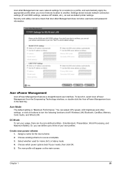
...Wired LAN. You can define up to use as default printer settings. Entertainment, Presentation, Word Processing, and Maximum Battery. Security and safety concerns mean that Acer eNet Management does not store username and password information. Assign a name for mains (AC) or batery mode....another. Choose which power options best fit your usage, there are four pre-defined profiles - Acer ePower Management Acer ePower Management features a straightforward user interface. Acer Mode The default setting is "Maximum Performance." Or, you move fromone location to turn the ...
...Wired LAN. You can define up to use as default printer settings. Entertainment, Presentation, Word Processing, and Maximum Battery. Security and safety concerns mean that Acer eNet Management does not store username and password information. Assign a name for mains (AC) or batery mode....another. Choose which power options best fit your usage, there are four pre-defined profiles - Acer ePower Management Acer ePower Management features a straightforward user interface. Acer Mode The default setting is "Maximum Performance." Or, you move fromone location to turn the ...
TravelMate 4070 Service Guide
Page 31
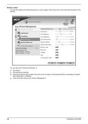
You can also click "Advanced Settings" to: T Set alarms. T Re-load factory defaults. T Select what actions will be taken when the cover is closed, and set passwords for accessing the system after Hibernation or Standby. Battery status For real-time battery life estimates based on current usage, referto the panel on the lower left-hand side of the window. T View information about Acer ePower Management. 26 TravelMate 4070/4080
You can also click "Advanced Settings" to: T Set alarms. T Re-load factory defaults. T Select what actions will be taken when the cover is closed, and set passwords for accessing the system after Hibernation or Standby. Battery status For real-time battery life estimates based on current usage, referto the panel on the lower left-hand side of the window. T View information about Acer ePower Management. 26 TravelMate 4070/4080
TravelMate 4070 Service Guide
Page 39
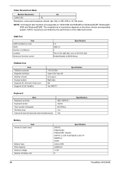
...number of keypads Windows keys Internal & external keyboard work simultaneously KBC NS97551 Darfon 88-/89-key Yes Yes Specification Battery Item Vendor & model name Battery Type Pack capacity Nominal voltage Number of the attached monitor. USB Port Item USB Compliancy Level OHCI Number of ...resolutions depends on the front side Enable/Disable by the performance of battery cell Specification SANYO PANASONIC PANASONIC (RoHS) SANYO LI-ION 4UR18650F-2-QC141 SIMPPLO SONY Lithium-ION 4400mAH 14.8V 8 34 TravelMate 4070/4080 one on the driver version and operating system. Video Resolutions ...
...number of keypads Windows keys Internal & external keyboard work simultaneously KBC NS97551 Darfon 88-/89-key Yes Yes Specification Battery Item Vendor & model name Battery Type Pack capacity Nominal voltage Number of the attached monitor. USB Port Item USB Compliancy Level OHCI Number of ...resolutions depends on the front side Enable/Disable by the performance of battery cell Specification SANYO PANASONIC PANASONIC (RoHS) SANYO LI-ION 4UR18650F-2-QC141 SIMPPLO SONY Lithium-ION 4400mAH 14.8V 8 34 TravelMate 4070/4080 one on the driver version and operating system. Video Resolutions ...

TravelMate 4070 Service Guide
Page 40
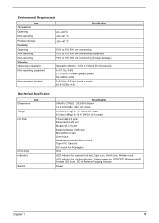
Battery Item Package configuration Package voltage Specification 4S2P for Sanyo and Panasonic 4S1P for Sanyo QC141,SIMPPLO and SONY 41.8V / 9.6V LCD Item Vendor & model ...
Battery Item Package configuration Package voltage Specification 4S2P for Sanyo and Panasonic 4S1P for Sanyo QC141,SIMPPLO and SONY 41.8V / 9.6V LCD Item Vendor & model ...
TravelMate 4070 Service Guide
Page 42
... key: Caps Lock, Scroll Lock, NUmber lock LED indicator for function indicator: System power-on, HDD/ODD, Wireless on/off, Arcade LED mode, DC-in, Battery/Charging indicator Power Chapter 1 37
... key: Caps Lock, Scroll Lock, NUmber lock LED indicator for function indicator: System power-on, HDD/ODD, Wireless on/off, Arcade LED mode, DC-in, Battery/Charging indicator Power Chapter 1 37

TravelMate 4070 Service Guide
Page 55
... ROM. Recover BIOS from Crisis Recovery Diskette 1. BIOS Flash Utility The BIOS flash memory update is not completely loaded. Then you power on . If the battery pack does not contain enough power to create crisis recovery diskette. Run cs.bat and follow its instructions to finish BIOS flash, you use the...
... ROM. Recover BIOS from Crisis Recovery Diskette 1. BIOS Flash Utility The BIOS flash memory update is not completely loaded. Then you power on . If the battery pack does not contain enough power to create crisis recovery diskette. Run cs.bat and follow its instructions to finish BIOS flash, you use the...
TravelMate 4070 Service Guide
Page 59
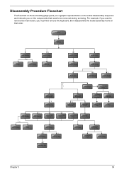
... HDD Holder *2 Dimm Cover Memory *1 Modem Cover *2 Modem Board Hinge Caps *2 Middle Cover Keyboard *6 LCD Module *2 Launch Board Lower Case Assembly *2 FDD Module *3 *3 *11 *4 RTC Battery *3 Mini PCI Card Plate Upper Case Assembly Disconnect Wireless LAN Antenna *4 Thermal Module *4 Wireless LAN Antenna Touchpad Cover Wireless LAN Card CPU ODD Module *4 HDD...
... HDD Holder *2 Dimm Cover Memory *1 Modem Cover *2 Modem Board Hinge Caps *2 Middle Cover Keyboard *6 LCD Module *2 Launch Board Lower Case Assembly *2 FDD Module *3 *3 *11 *4 RTC Battery *3 Mini PCI Card Plate Upper Case Assembly Disconnect Wireless LAN Antenna *4 Thermal Module *4 Wireless LAN Antenna Touchpad Cover Wireless LAN Card CPU ODD Module *4 HDD...

TravelMate 4070 Service Guide
Page 61
Chapter 3 56 Removing the Battery 1. Unlatch the battery latch then remove the battery.
Chapter 3 56 Removing the Battery 1. Unlatch the battery latch then remove the battery.

TravelMate 4070 Service Guide
Page 62
Removing the Hard Disc Drive Module 1. Then remove the HDD cover. 4. Remove two screw securing the HDD bracket. 2. Take out the HDD from the HDD bracket. 57 Chapter 3 See "Removing the Battery" on the other side. 3. Disassembling the Hard Disc Drive Module 1. Remove the HDD module. Pull the HDD module backwards as shown. 5. Remove the screw securing the hard disk drive (HDD) cover. 3. Remove the other two screw on page 56. 2.
Removing the Hard Disc Drive Module 1. Then remove the HDD cover. 4. Remove two screw securing the HDD bracket. 2. Take out the HDD from the HDD bracket. 57 Chapter 3 See "Removing the Battery" on the other side. 3. Disassembling the Hard Disc Drive Module 1. Remove the HDD module. Pull the HDD module backwards as shown. 5. Remove the screw securing the hard disk drive (HDD) cover. 3. Remove the other two screw on page 56. 2.
TravelMate 4070 Service Guide
Page 63
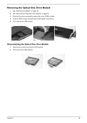
Removing the Optical Disc Drive Module 1. Then remove the ODD module. Push the ODD module outwards with a flat headed screw driver. 5. Disassembling the Optical Disc Drive Module 1. Remove the screw securing the optical disc drove (ODD) module. 4. Then remove the ODD bracket. Remove two screws securing the ODD bracket. 2. Chapter 3 58 See "Removing the Hard Disc Drive Module" on page 56. 2. See "Removing the Battery" on page 57. 3.
Removing the Optical Disc Drive Module 1. Then remove the ODD module. Push the ODD module outwards with a flat headed screw driver. 5. Disassembling the Optical Disc Drive Module 1. Remove the screw securing the optical disc drove (ODD) module. 4. Then remove the ODD bracket. Remove two screws securing the ODD bracket. 2. Chapter 3 58 See "Removing the Hard Disc Drive Module" on page 56. 2. See "Removing the Battery" on page 57. 3.

TravelMate 4070 Service Guide
Page 64
Then remove the memory from the DIMM socket. 59 Chapter 3 Remove the two screws securing the DIMM cover then remove the DIMM cover. 3. Pop out the memory. 4. Removing the Memory 1. See "Removing the Battery" on page 56. 2.
Then remove the memory from the DIMM socket. 59 Chapter 3 Remove the two screws securing the DIMM cover then remove the DIMM cover. 3. Pop out the memory. 4. Removing the Memory 1. See "Removing the Battery" on page 56. 2.

TravelMate 4070 Service Guide
Page 65
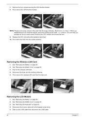
...page 60. 4. See "Removing the Keyboard" on page 56. 2. Chapter 3 60 Removing the LCD Module Removing the Middle Cover 1. See "Removing the Battery" on page 60. 3. Remove the four screws securing the keyboard. 4. Turn the keyboard over as image shows. 3. Disconnect the fan cable. 6. ...See "Removing the Middle Cover" on page 56. 2. Removing the Fan, the CPU Thermal Module and the CPU 1. See "Removing the Battery" on page 60. 3. Then detach the fan from the main unit. Disconnect the keyboard cable then remove the keyboard. See "Removing the Middle Cover" on...
...page 60. 4. See "Removing the Keyboard" on page 56. 2. Chapter 3 60 Removing the LCD Module Removing the Middle Cover 1. See "Removing the Battery" on page 60. 3. Remove the four screws securing the keyboard. 4. Turn the keyboard over as image shows. 3. Disconnect the fan cable. 6. ...See "Removing the Middle Cover" on page 56. 2. Removing the Fan, the CPU Thermal Module and the CPU 1. See "Removing the Battery" on page 60. 3. Then detach the fan from the main unit. Disconnect the keyboard cable then remove the keyboard. See "Removing the Middle Cover" on...
TravelMate 4070 Service Guide
Page 66
..., therefore the CPU module can be secured well. 9. Then detch the CPU from the main unit. Pop out the wireless LAN card. 4. See "Removing the Battery" on page 60. 3. See "Removing the Middle Cover" on page 56. 2. Disconnect the inverter cable with a flat headed screw driver. 10. NOTE: Please remove the... disconnect the LVDS cable. 61 Chapter 3 Start from 4, 3, 2 then 1. Release the CPU lock with a flat headed screw driver. 5. Removing the LCD Module 1. See "Removing the Battery" on page 56. 2. 7. Then remove the CPU thermal module.
..., therefore the CPU module can be secured well. 9. Then detch the CPU from the main unit. Pop out the wireless LAN card. 4. See "Removing the Battery" on page 60. 3. See "Removing the Middle Cover" on page 56. 2. Disconnect the inverter cable with a flat headed screw driver. 10. NOTE: Please remove the... disconnect the LVDS cable. 61 Chapter 3 Start from 4, 3, 2 then 1. Release the CPU lock with a flat headed screw driver. 5. Removing the LCD Module 1. See "Removing the Battery" on page 56. 2. 7. Then remove the CPU thermal module.

TravelMate 4070 Service Guide
Page 68
.... 10. See "Removing the LCD Module" on page 60. 5. See "Removing the Keyboard" on page 56. 2. Disconnect the LCD inverter cable. 13. See "Removing the Battery" on page 60. 4. Remove the four screws securing the LCD bezel. 9.
.... 10. See "Removing the LCD Module" on page 60. 5. See "Removing the Keyboard" on page 56. 2. Disconnect the LCD inverter cable. 13. See "Removing the Battery" on page 60. 4. Remove the four screws securing the LCD bezel. 9.

TravelMate 4070 Service Guide
Page 70
... Case Assembly 1. See "Removing the Memory" on page 60. 6. See "Removing the Memory" on page 56. 2. Then detach the upper case assembly. See "Removing the Battery" on page 59. 5. Disconnect the touchpad cable. 9. See "Removing the Optical Disc Drive Module" on page 58. 4. Remove the three screws securing the upper case... Disc Drive Module" on page 56.. 2. Tear off the tape holding the power board cable then remove the power board. 65 Chapter 3 See "Removing the Battery" on page 57. 3. See "Removing the Hard Disc Drive Module" on page 57. 3.
... Case Assembly 1. See "Removing the Memory" on page 60. 6. See "Removing the Memory" on page 56. 2. Then detach the upper case assembly. See "Removing the Battery" on page 59. 5. Disconnect the touchpad cable. 9. See "Removing the Optical Disc Drive Module" on page 58. 4. Remove the three screws securing the upper case... Disc Drive Module" on page 56.. 2. Tear off the tape holding the power board cable then remove the power board. 65 Chapter 3 See "Removing the Battery" on page 57. 3. See "Removing the Hard Disc Drive Module" on page 57. 3.


