TravelMate 240/250 Service Guide
Page 7
... Utility 46 System Diagnostic Diskette 46 Chapter 3 Machine Disassembly and Replacement 48 General Information 49 Disassembly Procedure Flowchart 50 Removing the Battery 52 Removing the Memory Module 53 Removing the Modem Board 54 ...Battery 93 Chapter 4 Troubleshooting 94 System Check Procedures 95 Power-On Self-Test (POST) Error Message 99 Index of Error Messages 100 Index of Symptom-to-FRU Error Message 103 Intermittent Problems 106 Undetermined Problems 107 Chapter 5 Jumper and Connector Locations 108 Chapter 6 FRU (Field Replaceable Unit) List 112 TravelMate 240...
... Utility 46 System Diagnostic Diskette 46 Chapter 3 Machine Disassembly and Replacement 48 General Information 49 Disassembly Procedure Flowchart 50 Removing the Battery 52 Removing the Memory Module 53 Removing the Modem Board 54 ...Battery 93 Chapter 4 Troubleshooting 94 System Check Procedures 95 Power-On Self-Test (POST) Error Message 99 Index of Error Messages 100 Index of Symptom-to-FRU Error Message 103 Intermittent Problems 106 Undetermined Problems 107 Chapter 5 Jumper and Connector Locations 108 Chapter 6 FRU (Field Replaceable Unit) List 112 TravelMate 240...
TravelMate 240/250 Service Guide
Page 36
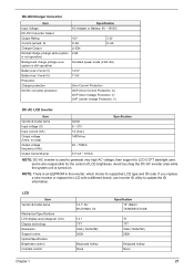
... Output Normal charge (charge while system is not operative) Background charge (charge even system is still operative) Battery-low 2 level (V) Battery-low 3 level (V) Protection Charger protection DC/DC converter protection Specification AC Adapter or Battery: 8V - 19VDC +5V 0~5A Li-ION 2.8A 3.3V 0~4A Constant power mode (2.8A~0A) 12...None Chapter 1 27 NOTE: There is an EEPROM in the inverter, which stores its supported LCD type and ID code. If you replace a new inverter or replace the LCD with a different brand, use Inverter ID utility to LCD CCFT backlight user, and is turned on.
... Output Normal charge (charge while system is not operative) Background charge (charge even system is still operative) Battery-low 2 level (V) Battery-low 3 level (V) Protection Charger protection DC/DC converter protection Specification AC Adapter or Battery: 8V - 19VDC +5V 0~5A Li-ION 2.8A 3.3V 0~4A Constant power mode (2.8A~0A) 12...None Chapter 1 27 NOTE: There is an EEPROM in the inverter, which stores its supported LCD type and ID code. If you replace a new inverter or replace the LCD with a different brand, use Inverter ID utility to LCD CCFT backlight user, and is turned on.
TravelMate 240/250 Service Guide
Page 78
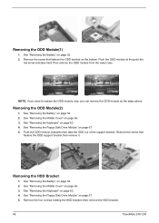
... page 52. 2. Push the ODD module outwards then take the ODD out of the support bracket. See "Removing the Battery" on page 67. 5. NOTE: If you need to replace the ODD module only, you can remove the ODD module as the steps above. See "Removing the Floppy Disk Drive ...Cover" on page 52. 2. Remove the screw that fastens the ODD support bracket then remove it. See "Removing the Battery" on page 56. 3. Removing the HDD Bracket 1. Remove the four screws holding the HDD bracket, then remove the HDD bracket. 69 TravelMate 240/ 250 See "Removing the Keyboard" on the bottom.
... page 52. 2. Push the ODD module outwards then take the ODD out of the support bracket. See "Removing the Battery" on page 67. 5. NOTE: If you need to replace the ODD module only, you can remove the ODD module as the steps above. See "Removing the Floppy Disk Drive ...Cover" on page 52. 2. Remove the screw that fastens the ODD support bracket then remove it. See "Removing the Battery" on page 56. 3. Removing the HDD Bracket 1. Remove the four screws holding the HDD bracket, then remove the HDD bracket. 69 TravelMate 240/ 250 See "Removing the Keyboard" on the bottom.
TravelMate 240/250 Service Guide
Page 106
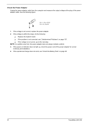
... the Battery Pack" on page 98. 97 TravelMate 240/ 250 T If the problem is not correct, go to +20.5V Pin 2: 0V, Ground 1. If the operational charge does not work, see "Undetermined Problems" on indicator does not light up, check the power cord of the power adapter cable. See the following : T Replace the ...System board. If the voltage is not correct, replace the power adapter. 2. If the power-on page 107.
... the Battery Pack" on page 98. 97 TravelMate 240/ 250 T If the problem is not correct, go to +20.5V Pin 2: 0V, Ground 1. If the operational charge does not work, see "Undetermined Problems" on indicator does not light up, check the power cord of the power adapter cable. See the following : T Replace the ...System board. If the voltage is not correct, replace the power adapter. 2. If the power-on page 107.

TravelMate 240/250 Service Guide
Page 107
... Remaining are necessary if the pointer movement stops in control Panel 2. Chapter 4 98 Remove the battery pack and measure the voltage between battery terminals 1(+) and 6(ground). See the following actions one at a time to the touchpad pointer. Replace the system board. No service actions are correct. 3. If the voltage is not a hardware problem...
... Remaining are necessary if the pointer movement stops in control Panel 2. Chapter 4 98 Remove the battery pack and measure the voltage between battery terminals 1(+) and 6(ground). See the following actions one at a time to the touchpad pointer. Replace the system board. No service actions are correct. 3. If the voltage is not a hardware problem...
TravelMate 240/250 Service Guide
Page 109
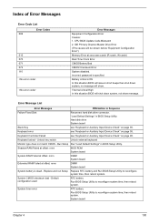
...password is dead - "Load Default Settings" in Sequence Failure Fixed Disk Reconnect hard disk drive connector. Default configuration used RTC battery Run BIOS Setup Utility to reconfigure system time, then reboot system. Index of Error Messages Error Code List Error Codes 006 010... Auxiliary Input Device Check" on page 95. System timer error RTC battery Run BIOS Setup Utility to reconfigure system time, then reboot system. System board Chapter 4 100 Replace and run Setup Replace RTC battery and Run BIOS Setup Utility to reconfigure system time, then reboot system...
...password is dead - "Load Default Settings" in Sequence Failure Fixed Disk Reconnect hard disk drive connector. Default configuration used RTC battery Run BIOS Setup Utility to reconfigure system time, then reboot system. Index of Error Messages Error Code List Error Codes 006 010... Auxiliary Input Device Check" on page 95. System timer error RTC battery Run BIOS Setup Utility to reconfigure system time, then reboot system. System board Chapter 4 100 Replace and run Setup Replace RTC battery and Run BIOS Setup Utility to reconfigure system time, then reboot system...
TravelMate 240/250 Service Guide
Page 116
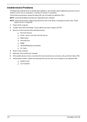
...Verify that all of the failure is inoperative. Visually check them for damage. Do not replace a non-defective FRU: T System board T LCD assembly 107 TravelMate 240/ 250 If any problems are found, replace the FRU. 3. If the problem does not recur, reconnect the removed devices one ... FRU. 7. Remove or disconnect all attached devices are supported by the computer. If the problem remains, replace the following devices: T Non-Acer devices T Printer, mouse, and other external devices T Battery pack T Hard disk drive T DIMM T CD-ROM/Diskette drive Module T PC Cards 4. Determine if...
...Verify that all of the failure is inoperative. Visually check them for damage. Do not replace a non-defective FRU: T System board T LCD assembly 107 TravelMate 240/ 250 If any problems are found, replace the FRU. 3. If the problem does not recur, reconnect the removed devices one ... FRU. 7. Remove or disconnect all attached devices are supported by the computer. If the problem remains, replace the following devices: T Non-Acer devices T Printer, mouse, and other external devices T Battery pack T Hard disk drive T DIMM T CD-ROM/Diskette drive Module T PC Cards 4. Determine if...
TravelMate 240/250 Service Guide
Page 153
A AC Adapter 28 AFLASH Utility 46 Audio 19 B Battery 26 battery pack charging indicator 12 BIOS 19 package 19 ROM size 19 ROM type 19 vendor 19 Version 19 BIOS Setup Utility 34 BIOS Supports protocol ... 29 Error Symptom-to-Spare Part Index 99 External CD-ROM Drive Check 95 F Features 1 Flash Utility 46 Floppy Disk Drive Interface 21 FRU (Field Replaceable Unit) List 112 H Hard disk 19, 21 Hard Disk Drive Module Disassembly 55 Hard Disk Standby Mode 29 Hardware Specifications and Configurations 19 HDD 19...
A AC Adapter 28 AFLASH Utility 46 Audio 19 B Battery 26 battery pack charging indicator 12 BIOS 19 package 19 ROM size 19 ROM type 19 vendor 19 Version 19 BIOS Setup Utility 34 BIOS Supports protocol ... 29 Error Symptom-to-Spare Part Index 99 External CD-ROM Drive Check 95 F Features 1 Flash Utility 46 Floppy Disk Drive Interface 21 FRU (Field Replaceable Unit) List 112 H Hard disk 19, 21 Hard Disk Drive Module Disassembly 55 Hard Disk Standby Mode 29 Hardware Specifications and Configurations 19 HDD 19...


