
Acer V5-471 Notebook Service Guide
Page 4
... information available on cards, modems, or extra memory capabilities). When ordering FRU parts: Check the most up-to the basic configuration for Acer's global product offering. In such cases, contact your regional Acer office to provide you with further technical details. Acer-authorized Service Providers: Your Acer office may have decided to extend the functionality...
... information available on cards, modems, or extra memory capabilities). When ordering FRU parts: Check the most up-to the basic configuration for Acer's global product offering. In such cases, contact your regional Acer office to provide you with further technical details. Acer-authorized Service Providers: Your Acer office may have decided to extend the functionality...
Acer V5-471 Notebook Service Guide
Page 5
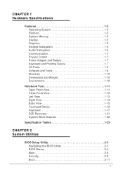
CHAPTER 1 Hardware Specifications Features 1-5 Operating System 1-5 Platform 1-5 System Memory 1-5 Display 1-5 Graphics 1-5 Storage Subsystem 1-6 Audio Subsystem 1-6 Communication 1-7 Privacy Control 1-7 Power Adapter and Battery 1-7 Keyboard and Pointing Device 1-7 I/O Ports 1-8 Software and Tools 1-8 Warranty 1-10 Dimensions and ...
CHAPTER 1 Hardware Specifications Features 1-5 Operating System 1-5 Platform 1-5 System Memory 1-5 Display 1-5 Graphics 1-5 Storage Subsystem 1-6 Audio Subsystem 1-6 Communication 1-7 Privacy Control 1-7 Power Adapter and Battery 1-7 Keyboard and Pointing Device 1-7 I/O Ports 1-8 Software and Tools 1-8 Warranty 1-10 Dimensions and ...
Acer V5-471 Notebook Service Guide
Page 12
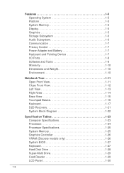
Features 1-5 Operating System 1-5 Platform 1-5 System Memory 1-5 Display 1-5 Graphics 1-5 Storage Subsystem 1-6 Audio Subsystem 1-6 Communication 1-7 Privacy Control 1-7 Power Adapter and Battery 1-7 Keyboard and Pointing Device 1-7 I/O Ports 1-8 Software ... 1-16 Keyboard 1-17 D2D Recovery 1-21 System Block Diagram 1-22 Specification Tables 1-23 Computer Specifications 1-23 Processor 1-24 Processor Specifications 1-25 System Memory 1-25 Graphics Controller 1-26 VRAM (Discrete models only 1-26 System BIOS 1-27 Keyboard 1-27 Hard Disk Drive 1-28 Super-Multi Drive 1-29...
Features 1-5 Operating System 1-5 Platform 1-5 System Memory 1-5 Display 1-5 Graphics 1-5 Storage Subsystem 1-6 Audio Subsystem 1-6 Communication 1-7 Privacy Control 1-7 Power Adapter and Battery 1-7 Keyboard and Pointing Device 1-7 I/O Ports 1-8 Software ... 1-16 Keyboard 1-17 D2D Recovery 1-21 System Block Diagram 1-22 Specification Tables 1-23 Computer Specifications 1-23 Processor 1-24 Processor Specifications 1-25 System Memory 1-25 Graphics Controller 1-26 VRAM (Discrete models only 1-26 System BIOS 1-27 Keyboard 1-27 Hard Disk Drive 1-28 Super-Multi Drive 1-29...
Acer V5-471 Notebook Service Guide
Page 15
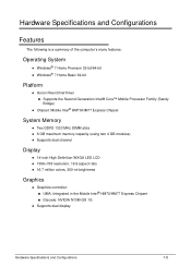
...® Core™ Mobile Processor Family (Sandy Bridge) Chipset: Mobile Intel® HM70/HM77 Express Chipset System Memory 0 Two DDR3 1333 MHz DIMM slots 8 GB maximum memory capacity (using two 4 GB modules) Supports dual channel Display 0 14-inch High Definition WXGA LED...
...® Core™ Mobile Processor Family (Sandy Bridge) Chipset: Mobile Intel® HM70/HM77 Express Chipset System Memory 0 Two DDR3 1333 MHz DIMM slots 8 GB maximum memory capacity (using two 4 GB modules) Supports dual channel Display 0 14-inch High Definition WXGA LED...
Acer V5-471 Notebook Service Guide
Page 25
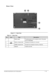
Releases the battery for removal. 3 DIMM compartment Houses the computer's memory modules. 4 Speaker Outputs sounds. Base View Table 1-5. Base View No. Icon Item 1 Battery pack 2 Battery release latch Description Provides power to the computer when the power cord is unplugged. Hardware Specifications and Configurations 1-15 Base View 0 Figure 1-5.
Releases the battery for removal. 3 DIMM compartment Houses the computer's memory modules. 4 Speaker Outputs sounds. Base View Table 1-5. Base View No. Icon Item 1 Battery pack 2 Battery release latch Description Provides power to the computer when the power cord is unplugged. Hardware Specifications and Configurations 1-15 Base View 0 Figure 1-5.
Acer V5-471 Notebook Service Guide
Page 35
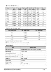
... at 85 °C SPL Spec (dBA) 28 31 34 37 40 System Memory Item Specification Memory controller Integrated in the Intel® Core™ Mobile Processor Memory size 1-, 2-, or 4 GB Number of DIMM socket 2 Maximum memory size per socket 4 GB Maximum system memory size 8 GB DIMM type DDR3 SDRAM DIMM speed 1333 MHz DIMM voltage...
... at 85 °C SPL Spec (dBA) 28 31 34 37 40 System Memory Item Specification Memory controller Integrated in the Intel® Core™ Mobile Processor Memory size 1-, 2-, or 4 GB Number of DIMM socket 2 Maximum memory size per socket 4 GB Maximum system memory size 8 GB DIMM type DDR3 SDRAM DIMM speed 1333 MHz DIMM voltage...
Acer V5-471 Notebook Service Guide
Page 36
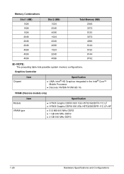
... H5TQ2G63DFR-11C LF+HF 512 MB 900 MHz DDR3 1 GB 900 MHz DDR3 2 GB 900 MHz DDR3 1-26 Hardware Specifications and Configurations Memory Combinations Slot 1 (MB) 1024 1024 1024 2048 2048 2048 4096 4096 4096 Slot 2 (MB) 1024 2048 4096 1024 2048 4096 1024 2048 4096 Total...
... H5TQ2G63DFR-11C LF+HF 512 MB 900 MHz DDR3 1 GB 900 MHz DDR3 2 GB 900 MHz DDR3 1-26 Hardware Specifications and Configurations Memory Combinations Slot 1 (MB) 1024 1024 1024 2048 2048 2048 4096 4096 4096 Slot 2 (MB) 1024 2048 4096 1024 2048 4096 1024 2048 4096 Total...
Acer V5-471 Notebook Service Guide
Page 39
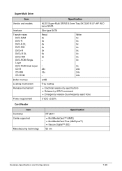
...-RAM DVD-R DVD-R DL DVD-RW DVD+R DVD+R DL DVD+RW DVD-ROM Single Layer DVD-ROM Dual Layer CD-R CD-RW CD-ROM Buffer memory Loading mechanism Release mechanism Power requirement Specification HLDS Super-Multi DRIVE 9.0mm Tray 8X GU61N LF+HF W/O bezel SATA Slim-type SATA Read 5x 8x...
...-RAM DVD-R DVD-R DL DVD-RW DVD+R DVD+R DL DVD+RW DVD-ROM Single Layer DVD-ROM Dual Layer CD-R CD-RW CD-ROM Buffer memory Loading mechanism Release mechanism Power requirement Specification HLDS Super-Multi DRIVE 9.0mm Tray 8X GU61N LF+HF W/O bezel SATA Slim-type SATA Read 5x 8x...
Acer V5-471 Notebook Service Guide
Page 45
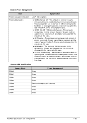
... the machine in this state. System DMA Specification Legacy Mode DMA0 DMA1 DMA2 DMA3 DMA4 DMA5 DMA6 DMA7 Power Management Free Free Free Free Direct memory access controller Free Free Free Hardware Specifications and Configurations 1-35 The computer dispatches user mode (application) threads and they execute. It is running through a mechanical...
... the machine in this state. System DMA Specification Legacy Mode DMA0 DMA1 DMA2 DMA3 DMA4 DMA5 DMA6 DMA7 Power Management Free Free Free Free Direct memory access controller Free Free Free Hardware Specifications and Configurations 1-35 The computer dispatches user mode (application) threads and they execute. It is running through a mechanical...
Acer V5-471 Notebook Service Guide
Page 57
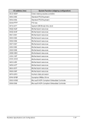
... 1000-100F FFFF-FFFF 0400-0453 0458-047F 0500-057F 0068-006F 00F0-00F0 EFA0-EFBF 0062-00062 0066-0066 System Function (shipping configuration) Direct memory access controller Standard PS/2 Keyboard Standard PS/2 Keyboard PCI bus System CMOS/real time clock Motherboard resources Motherboard resources Motherboard resources Motherboard resources Motherboard resources...
... 1000-100F FFFF-FFFF 0400-0453 0458-047F 0500-057F 0068-006F 00F0-00F0 EFA0-EFBF 0062-00062 0066-0066 System Function (shipping configuration) Direct memory access controller Standard PS/2 Keyboard Standard PS/2 Keyboard PCI bus System CMOS/real time clock Motherboard resources Motherboard resources Motherboard resources Motherboard resources Motherboard resources...
Acer V5-471 Notebook Service Guide
Page 66
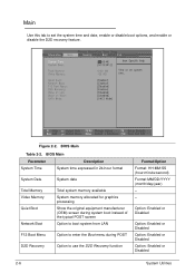
... Utilities Figure 2-2. BIOS Main Parameter System Time Description System time expressed in 24-hour format System Date System date Total Memory Video Memory Quiet Boot Network Boot Total system memory available System memory allocated for graphics processing Show the original equipment manufacturer (OEM) screen during system boot instead of the typical POST screen Option...
... Utilities Figure 2-2. BIOS Main Parameter System Time Description System time expressed in 24-hour format System Date System date Total Memory Video Memory Quiet Boot Network Boot Total system memory available System memory allocated for graphics processing Show the original equipment manufacturer (OEM) screen during system boot instead of the typical POST screen Option...
Acer V5-471 Notebook Service Guide
Page 73
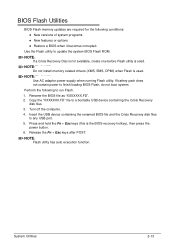
... utility. Rename the BIOS file as "XXXXXXX.FD". 2. Press and hold the Fn + Esc keys (this is used . NOTE: NOTE: Do not install memory related drivers (XMS, EMS, DPMI) when Flash is the BIOS recovery hotkey), then press the power button. 6. NOTE: NOTE: If a Crisis Recovery Disc... is not available, create one before Flash utility is used . BIOS Flash Utilities 0 BIOS Flash memory updates are required for the following to any USB port. 5. Turn off the computer. 4. Copy the "XXXXXXX.FD" file to a bootable USB device ...
... utility. Rename the BIOS file as "XXXXXXX.FD". 2. Press and hold the Fn + Esc keys (this is used . NOTE: NOTE: Do not install memory related drivers (XMS, EMS, DPMI) when Flash is the BIOS recovery hotkey), then press the power button. 6. NOTE: NOTE: If a Crisis Recovery Disc... is not available, create one before Flash utility is used . BIOS Flash Utilities 0 BIOS Flash memory updates are required for the following to any USB port. 5. Turn off the computer. 4. Copy the "XXXXXXX.FD" file to a bootable USB device ...
Acer V5-471 Notebook Service Guide
Page 78
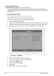
At the command prompt, navigate to EEPROM (Electrically Erasable Programmable Read-Only Memory). Using DMI Tools 0 The DMI (Desktop Management Interface) Tool copies BIOS information to the MAC folder. 7. Connect the USB HDD and reboot the computer. 6. Press ...
At the command prompt, navigate to EEPROM (Electrically Erasable Programmable Read-Only Memory). Using DMI Tools 0 The DMI (Desktop Management Interface) Tool copies BIOS information to the MAC folder. 7. Connect the USB HDD and reboot the computer. 6. Press ...
Acer V5-471 Notebook Service Guide
Page 164
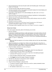
... POST or video appears on the external display only, refer to the User Manual for instructions on page 4-7. 7. Start the computer. Reinstall the memory modules. 11. Boot the computer. Refer to the "LCD Failure" section on adjusting the settings. Check the Device Manager to determine that the ...;There are no device conflicts No hardware is faulty and should be replaced. Remove and reinstall the video driver. 6. Remove any memory cards and CD/DVD discs. 9. The same goes for 10 seconds. 4. If the display is only abnormal in an application, check the ...
... POST or video appears on the external display only, refer to the User Manual for instructions on page 4-7. 7. Start the computer. Reinstall the memory modules. 11. Boot the computer. Refer to the "LCD Failure" section on adjusting the settings. Check the Device Manager to determine that the ...;There are no device conflicts No hardware is faulty and should be replaced. Remove and reinstall the video driver. 6. Remove any memory cards and CD/DVD discs. 9. The same goes for 10 seconds. 4. If the display is only abnormal in an application, check the ...
Acer V5-471 Notebook Service Guide
Page 165
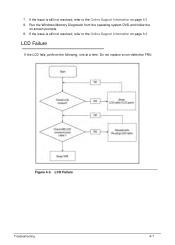
Run the Windows Memory Diagnostic from the operating system DVD and follow the on page 8-3 8. 7. Do not replace a non-defective FRU: Figure 4-3. If the issue is still not resolved, refer to the Online Support Information on -screen prompts. 9. If the issue is still not resolved, refer to the Online Support Information on page 8-3 LCD Failure 0 If the LCD fails, perform the following, one at a time. LCD Failure Troubleshooting 4-7
Run the Windows Memory Diagnostic from the operating system DVD and follow the on page 8-3 8. 7. Do not replace a non-defective FRU: Figure 4-3. If the issue is still not resolved, refer to the Online Support Information on -screen prompts. 9. If the issue is still not resolved, refer to the Online Support Information on page 8-3 LCD Failure 0 If the LCD fails, perform the following, one at a time. LCD Failure Troubleshooting 4-7

Acer V5-471 Notebook Service Guide
Page 178
... system down . Error Codes Error Codes Error Messages 006 Equipment Configuration Error Causes: 1. In this situation BIOS will be shown before "Equipment Configuration Error") 010 Memory Error at xxxx:xxxx:xxxxh (R:xxxxh, W:xxxxh) 070 Real Time Clock Error 071 CMOS Battery Bad 072 CMOS Checksum Error 110 System is displayed. Battery...
... system down . Error Codes Error Codes Error Messages 006 Equipment Configuration Error Causes: 1. In this situation BIOS will be shown before "Equipment Configuration Error") 010 Memory Error at xxxx:xxxx:xxxxh (R:xxxxh, W:xxxxh) 070 Real Time Clock Error 071 CMOS Battery Bad 072 CMOS Checksum Error 110 System is displayed. Battery...
Acer V5-471 Notebook Service Guide
Page 179
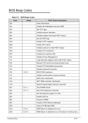
...during warm boot 13h Initialize PCI Bus Mastering devices 14h Initialize keyboard controller 16h 1-2-2-3 BIOS ROM checksum 17h Initialize cache before memory autosize 18h 8254 timer initialization 1Ah 8237 DMA controller initialization 1Ch Reset Programmable Interrupt Controller 20h 1-3-1-1 Test DRAM refresh 22h ... Test 8742 Keyboard Controller 24h Set ES segment register to 4 GB 26h Enable A20 line 28h Autosize DRAM 29h Initialize POST Memory Manager 2Ah Clear 215 KB base RAM 2Ch 1-3-4-1 RAM failure on address line xxxx 2Eh 1-3-4-3 RAM failure on data bits ...
...during warm boot 13h Initialize PCI Bus Mastering devices 14h Initialize keyboard controller 16h 1-2-2-3 BIOS ROM checksum 17h Initialize cache before memory autosize 18h 8254 timer initialization 1Ah 8237 DMA controller initialization 1Ch Reset Programmable Interrupt Controller 20h 1-3-1-1 Test DRAM refresh 22h ... Test 8742 Keyboard Controller 24h Set ES segment register to 4 GB 26h Enable A20 line 28h Autosize DRAM 29h Initialize POST Memory Manager 2Ah Clear 215 KB base RAM 2Ch 1-3-4-1 RAM failure on address line xxxx 2Eh 1-3-4-3 RAM failure on data bits ...
Acer V5-471 Notebook Service Guide
Page 180
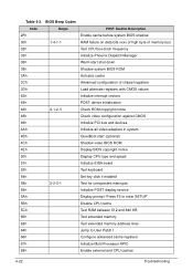
... 2Fh Beeps POST Routine Description Enable cache before system BIOS shadow 30h 1-4-1-1 RAM failure on data bits xxxx of high byte of memory bus 32h Test CPU bus-clock frequency 33h Initialize Phoenix Dispatch Manager 36h Warm start shut down 38h Shadow system BIOS ROM 3Ah Autosize ... prompt "Press F2 to enter SETUP" 5Bh Disable CPU cache 5Ch Test RAM between 512 and 640 KB 60h Test extended memory 62h Test extended memory address lines 64h Jump to User Patch1 66h Configure advanced cache registers 67h Initialize Multi Processor APIC 68h Enable external and CPU caches...
... 2Fh Beeps POST Routine Description Enable cache before system BIOS shadow 30h 1-4-1-1 RAM failure on data bits xxxx of high byte of memory bus 32h Test CPU bus-clock frequency 33h Initialize Phoenix Dispatch Manager 36h Warm start shut down 38h Shadow system BIOS ROM 3Ah Autosize ... prompt "Press F2 to enter SETUP" 5Bh Disable CPU cache 5Ch Test RAM between 512 and 640 KB 60h Test extended memory 62h Test extended memory address lines 64h Jump to User Patch1 66h Configure advanced cache registers 67h Initialize Multi Processor APIC 68h Enable external and CPU caches...
Acer V5-471 Notebook Service Guide
Page 183
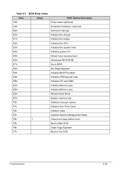
... E8h Set Huge Segment E9h Initialize Multi Processor EAh Initialize OEM special code EBh Initialize PIC and DMA ECh Initialize Memory type EDh Initialize Memory size EEh Shadow Boot Block EFh System memory test F0h Initialize interrupt vectors F1h Initialize Run Time Clock F2h Initialize video F3h Initialize System Management Mode F4h 1 Output...
... E8h Set Huge Segment E9h Initialize Multi Processor EAh Initialize OEM special code EBh Initialize PIC and DMA ECh Initialize Memory type EDh Initialize Memory size EEh Shadow Boot Block EFh System memory test F0h Initialize interrupt vectors F1h Initialize Run Time Clock F2h Initialize video F3h Initialize System Management Mode F4h 1 Output...
Acer V5-471 Notebook Service Guide
Page 187
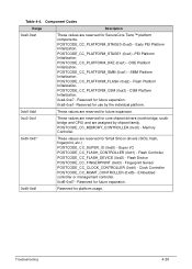
...) - POSTCODE_CC_PLATFORM_CSM (0xa3) - POSTCODE_CC_MEMORY_CONTROLLER (0xc0) - Reserved for future expansion. 0xd8-0xdf Reserved for SecureCore Tiano™ platform components. DXE Platform Initialization. CSM Platform Initialization. 0xa4-0xa7 - Memory Controller. 0xd0-0xd7 These values are assigned by chipset family. Table 4-4. Flash Device POSTCODE_CC_FINGERPRINT (0xd3) - Troubleshooting 4-29 Component Codes Range Description 0xa0-0xaf These values...
...) - POSTCODE_CC_PLATFORM_CSM (0xa3) - POSTCODE_CC_MEMORY_CONTROLLER (0xc0) - Reserved for future expansion. 0xd8-0xdf Reserved for SecureCore Tiano™ platform components. DXE Platform Initialization. CSM Platform Initialization. 0xa4-0xa7 - Memory Controller. 0xd0-0xd7 These values are assigned by chipset family. Table 4-4. Flash Device POSTCODE_CC_FINGERPRINT (0xd3) - Troubleshooting 4-29 Component Codes Range Description 0xa0-0xaf These values...


