User Manual
Page 64
...The computer may want to use the computer again, open the display; Preparing the computer Before moving the computer, close the display. then press and release the power button. When you are taking the computer to shut down the computer: Press the Windows key + and click Settings > Power then click... anything with you other than your computer in the meeting will be longer, or if your computer If your meeting room. then press and release the power button. Then close and latch the display cover to plug in your computer. You can put the computer in Sleep mode for ...
...The computer may want to use the computer again, open the display; Preparing the computer Before moving the computer, close the display. then press and release the power button. When you are taking the computer to shut down the computer: Press the Windows key + and click Settings > Power then click... anything with you other than your computer in the meeting will be longer, or if your computer If your meeting room. then press and release the power button. Then close and latch the display cover to plug in your computer. You can put the computer in Sleep mode for ...

User Manual
Page 87
... toggle the display back to the line-out port on the computer, the internal speakers automatically turn the display back on the taskbar. Press and release the power button to eject the tray. In Windows, look at the volume control icon on the optical drive. Simply insert the tip of a pen...
... toggle the display back to the line-out port on the computer, the internal speakers automatically turn the display back on the taskbar. Press and release the power button to eject the tray. In Windows, look at the volume control icon on the optical drive. Simply insert the tip of a pen...

User Manual
Page 92
... the background, swipe the right-hand edge of the screen inwards and tap Settings > Change PC settings > Personalize. Tap and drag the tile downwards and release it to appear. To change the background, swipe the right-hand edge of the screen inwards and tap Settings > Change PC settings > Personalize. Tap Start...
... the background, swipe the right-hand edge of the screen inwards and tap Settings > Change PC settings > Personalize. Tap and drag the tile downwards and release it to appear. To change the background, swipe the right-hand edge of the screen inwards and tap Settings > Change PC settings > Personalize. Tap Start...

User Manual
Page 94
Tap and drag the app downwards and release it . If you're in All apps and you want to taskbar from Store. You will need to have a Microsoft ID to ... they? If you're in All apps and you want to make a app appear on Start, tap and drag the app downwards and release it. Select Pin to make a app appear on the taskbar in Desktop, tap and drag the app downwards and... release it . You can 't find apps like to see the list of the app you would like Notepad and Paint! Swipe the right-...
Tap and drag the app downwards and release it . If you're in All apps and you want to taskbar from Store. You will need to have a Microsoft ID to ... they? If you're in All apps and you want to make a app appear on Start, tap and drag the app downwards and release it. Select Pin to make a app appear on the taskbar in Desktop, tap and drag the app downwards and... release it . You can 't find apps like to see the list of the app you would like Notepad and Paint! Swipe the right-...

Acer S7-391 Notebook Service Guide
Page 51
... used . If battery pack does not contain power to update the system BIOS Flash ROM. Press and hold the Fn + Esc keys (this is used . Release the Fn + Esc keys after POST. Use the Flash utility to finish loading BIOS Flash, do not boot system. NOTE: NOTE: If a Crisis Recovery Disc...
... used . If battery pack does not contain power to update the system BIOS Flash ROM. Press and hold the Fn + Esc keys (this is used . Release the Fn + Esc keys after POST. Use the Flash utility to finish loading BIOS Flash, do not boot system. NOTE: NOTE: If a Crisis Recovery Disc...

Acer S7-391 Notebook Service Guide
Page 68
Speaker Cable 4. Figure 3-9. Removing the Left and Right Speakers 0 1. Figure 3-10. Upper Case Assembly Latches 3-10 Machine Maintenance Perform the "Removing the Lower Case" procedure described on page 3-8. 3. Perform the "Removing the Battery Pack" procedure described on page 3-7. 2. Release the speaker cable from the mainboard. Disconnect the speaker's cable from the latches securing it to the upper case assembly.
Speaker Cable 4. Figure 3-9. Removing the Left and Right Speakers 0 1. Figure 3-10. Upper Case Assembly Latches 3-10 Machine Maintenance Perform the "Removing the Lower Case" procedure described on page 3-8. 3. Perform the "Removing the Battery Pack" procedure described on page 3-7. 2. Release the speaker cable from the mainboard. Disconnect the speaker's cable from the latches securing it to the upper case assembly.

Acer S7-391 Notebook Service Guide
Page 71
Perform the "Removing the Battery Pack" procedure described on page 3-7. 2. Remove the screw securing the hold sensor cable (2). Perform the "Removing the Lower Case" procedure described on page 3-8. 3. Hold Sensor Board Screw Table 3-16. Figure 3-15. Hold Sensor Cable 4. Screw Step Hold Sensor Board Disassembly Screw M2 x L2 Machine Maintenance Quantity 1 Screw Type 3-13 Figure 3-16. Release the connector latch (1) from the mainboard, then disconnect the hold sensor board to the upper case assembly. Removing the Hold Sensor Board 0 1.
Perform the "Removing the Battery Pack" procedure described on page 3-7. 2. Remove the screw securing the hold sensor cable (2). Perform the "Removing the Lower Case" procedure described on page 3-8. 3. Hold Sensor Board Screw Table 3-16. Figure 3-15. Hold Sensor Cable 4. Screw Step Hold Sensor Board Disassembly Screw M2 x L2 Machine Maintenance Quantity 1 Screw Type 3-13 Figure 3-16. Release the connector latch (1) from the mainboard, then disconnect the hold sensor board to the upper case assembly. Removing the Hold Sensor Board 0 1.

Acer S7-391 Notebook Service Guide
Page 72
Follow the local regulations for disposing this type of circuit board. 6. Figure 3-18. Hold Sensor Board NOTE: NOTE: A circuit board that is > 10cm2 has been highlighted with a yellow rectangle in Figure 3-17. Hold Sensor Cable 3-14 Machine Maintenance Detach the hold sensor board from the hold sensor board, then disconnect the hold sensor cable (2). Release the connector latch (1) from the upper case assembly. Figure 3-17. 5.
Follow the local regulations for disposing this type of circuit board. 6. Figure 3-18. Hold Sensor Board NOTE: NOTE: A circuit board that is > 10cm2 has been highlighted with a yellow rectangle in Figure 3-17. Hold Sensor Cable 3-14 Machine Maintenance Detach the hold sensor board from the hold sensor board, then disconnect the hold sensor cable (2). Release the connector latch (1) from the upper case assembly. Figure 3-17. 5.
Acer S7-391 Notebook Service Guide
Page 73
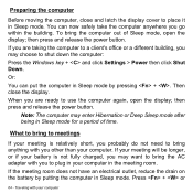
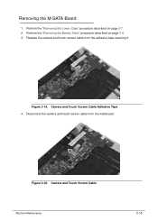
Perform the "Removing the Battery Pack" procedure described on page 3-7. 2. Release the camera and touch screen cable from the mainboard. Disconnect the camera and touch screen cable from the adhesive tape securing it. Figure 3-19. Camera and Touch Screen Cable Adhesive Tape 4. Camera and Touch Screen Cable Machine Maintenance 3-15 Figure 3-20. Removing the M-SATA Board 0 1. Perform the "Removing the Lower Case" procedure described on page 3-8. 3.
Perform the "Removing the Battery Pack" procedure described on page 3-7. 2. Release the camera and touch screen cable from the mainboard. Disconnect the camera and touch screen cable from the adhesive tape securing it. Figure 3-19. Camera and Touch Screen Cable Adhesive Tape 4. Camera and Touch Screen Cable Machine Maintenance 3-15 Figure 3-20. Removing the M-SATA Board 0 1. Perform the "Removing the Lower Case" procedure described on page 3-8. 3.

Acer S7-391 Notebook Service Guide
Page 75
Perform the "Removing the M-SATA Board" procedure described on page 3-8. 3. Small Fan Cable 5. Small Fan Screws Table 3-24. Release the connector latch (1) from the mainboard, then disconnect the small fan cable (2). Figure 3-24. Figure 3-23. Screws Step Small Fan Disassembly Screw M2 x L3 Machine ...
Perform the "Removing the M-SATA Board" procedure described on page 3-8. 3. Small Fan Cable 5. Small Fan Screws Table 3-24. Release the connector latch (1) from the mainboard, then disconnect the small fan cable (2). Figure 3-24. Figure 3-23. Screws Step Small Fan Disassembly Screw M2 x L3 Machine ...

Acer S7-391 Notebook Service Guide
Page 77
Release the LCD cable from the mainboard. Disconnect the LCD cable from the adhesive tape securing it. Perform the "Removing the Lower Case" procedure described on page 3-8. 3. Figure 3-26. Removing the Big Fan 0 1. LCD Cable Machine Maintenance 3-19 LCD Cable Adhesive Tape 4. Figure 3-27. Perform the "Removing the Battery Pack" procedure described on page 3-7. 2.
Release the LCD cable from the mainboard. Disconnect the LCD cable from the adhesive tape securing it. Perform the "Removing the Lower Case" procedure described on page 3-8. 3. Figure 3-26. Removing the Big Fan 0 1. LCD Cable Machine Maintenance 3-19 LCD Cable Adhesive Tape 4. Figure 3-27. Perform the "Removing the Battery Pack" procedure described on page 3-7. 2.

Acer S7-391 Notebook Service Guide
Page 78
Remove the two screws securing the big fan to the upper case assembly. Figure 3-29. Big Fan Cable 6. Figure 3-28. Big Fan Screws Table 3-29. Screws Step Big Fan Disassembly Screw M2 x L3 Quantity 2 Screw Type 3-20 Machine Maintenance Release the connector latch (1) from the mainboard, then disconnect the big fan cable (2). 5.
Remove the two screws securing the big fan to the upper case assembly. Figure 3-29. Big Fan Cable 6. Figure 3-28. Big Fan Screws Table 3-29. Screws Step Big Fan Disassembly Screw M2 x L3 Quantity 2 Screw Type 3-20 Machine Maintenance Release the connector latch (1) from the mainboard, then disconnect the big fan cable (2). 5.

Acer S7-391 Notebook Service Guide
Page 80
Touchpad Cable 4. Figure 3-32. Touchpad Cable Self Adhesive Tape 3-22 Machine Maintenance Figure 3-31. Release the connector latch (1) from the upper case assembly (3). Removing the Touchpad Module 0 1. Detach the cable from the touchpad board, then disconnect the touchpad cable (2). Perform the "Removing the Lower Case" procedure described on page 3-8. 3. Perform the "Removing the Battery Pack" procedure described on page 3-7. 2. Release the connector latch (1) from the mainboard, then disconnect the touchpad cable (2).
Touchpad Cable 4. Figure 3-32. Touchpad Cable Self Adhesive Tape 3-22 Machine Maintenance Figure 3-31. Release the connector latch (1) from the upper case assembly (3). Removing the Touchpad Module 0 1. Detach the cable from the touchpad board, then disconnect the touchpad cable (2). Perform the "Removing the Lower Case" procedure described on page 3-8. 3. Perform the "Removing the Battery Pack" procedure described on page 3-7. 2. Release the connector latch (1) from the mainboard, then disconnect the touchpad cable (2).

Acer S7-391 Notebook Service Guide
Page 81
Touchpad Module Self Adhesive Tape and Spacer Machine Maintenance 3-23 Figure 3-33. Screws Step Touchpad Module Disassembly Screw M1.2 × L1 Quantity 5 Screw Type 6. Figure 3-34. Remove the five screws securing the touchpad module to the upper case assembly. Touchpad Module Screws Table 3-33. Release the touchpad module from the adhesive tape and spacer securing it. 5.
Touchpad Module Self Adhesive Tape and Spacer Machine Maintenance 3-23 Figure 3-33. Screws Step Touchpad Module Disassembly Screw M1.2 × L1 Quantity 5 Screw Type 6. Figure 3-34. Remove the five screws securing the touchpad module to the upper case assembly. Touchpad Module Screws Table 3-33. Release the touchpad module from the adhesive tape and spacer securing it. 5.

Acer S7-391 Notebook Service Guide
Page 83
Removing the EL Small Board 0 1. Figure 3-36. Release the connector latch (1) from the upper case assembly (3). Perform the "Removing the Battery Pack" procedure described on page 3-7. 2. Detach the cable from the EL small board, then disconnect the EL small board cable (2). EL Small Board Cable Self Adhesive Tape Machine Maintenance 3-25 EL Small Board Cable 4. Release the connector latch (1) from the mainboard, then disconnect the EL small board cable (2). Perform the "Removing the Lower Case" procedure described on page 3-8. 3. Figure 3-37.
Removing the EL Small Board 0 1. Figure 3-36. Release the connector latch (1) from the upper case assembly (3). Perform the "Removing the Battery Pack" procedure described on page 3-7. 2. Detach the cable from the EL small board, then disconnect the EL small board cable (2). EL Small Board Cable Self Adhesive Tape Machine Maintenance 3-25 EL Small Board Cable 4. Release the connector latch (1) from the mainboard, then disconnect the EL small board cable (2). Perform the "Removing the Lower Case" procedure described on page 3-8. 3. Figure 3-37.

Acer S7-391 Notebook Service Guide
Page 85
Removing the Mainboard 0 1. Release the connector latch (1) from the mainboard, then disconnect the LED indicator cable (2). Perform the "Removing the Left and Right Speakers" procedure described on page 3-12. 5. ...
Removing the Mainboard 0 1. Release the connector latch (1) from the mainboard, then disconnect the LED indicator cable (2). Perform the "Removing the Left and Right Speakers" procedure described on page 3-12. 5. ...

Acer S7-391 Notebook Service Guide
Page 86
Keyboard Cable 13. Figure 3-41. Remove the six screws securing the mainboard to the upper case. 12. Mainboard Screws Table 3-41. Release the connector latch (1) from the mainboard, then disconnect the keyboard cable (2). Screws Step Mainboard Disassembly Screw M2 × L3 Quantity 6 Screw Type 3-28 Machine Maintenance Figure 3-40.
Keyboard Cable 13. Figure 3-41. Remove the six screws securing the mainboard to the upper case. 12. Mainboard Screws Table 3-41. Release the connector latch (1) from the mainboard, then disconnect the keyboard cable (2). Screws Step Mainboard Disassembly Screw M2 × L3 Quantity 6 Screw Type 3-28 Machine Maintenance Figure 3-40.

Acer S7-391 Notebook Service Guide
Page 89
18. Release the WLAN antenna cables from the mainboard. Figure 3-47. Figure 3-46. WLAN Antenna Cables Adhesive Tape Machine Maintenance 3-31 DC-In Module 19. Detach the DC-In module from the adhesive tape securing it.
18. Release the WLAN antenna cables from the mainboard. Figure 3-47. Figure 3-46. WLAN Antenna Cables Adhesive Tape Machine Maintenance 3-31 DC-In Module 19. Detach the DC-In module from the adhesive tape securing it.

Acer S7-391 Notebook Service Guide
Page 95
... Keyboard Disassembly Screw M1.2 × L1 Machine Maintenance Quantity 53 Screw Type 3-37 Perform the "Removing the Upper Case Assembly" procedure described on page 3-35. 2. Release the keyboard from the adhesive tape securing it to use excessive force when removing. 1. Figure 3-57. Removing the Keyboard 0 NOTE: NOTE: The keyboard is easily...
... Keyboard Disassembly Screw M1.2 × L1 Machine Maintenance Quantity 53 Screw Type 3-37 Perform the "Removing the Upper Case Assembly" procedure described on page 3-35. 2. Release the keyboard from the adhesive tape securing it to use excessive force when removing. 1. Figure 3-57. Removing the Keyboard 0 NOTE: NOTE: The keyboard is easily...

Acer S7-391 Notebook Service Guide
Page 179
All of its system functions are tested under Windows® 7 environment. Refer to the Compatibility Test Report released by Acer's internal testing department. Adapter DELTA 45W 19V 1.1x3.0x7.5 ADP-45ZD BA LF white, wall mount and brick type switching Adapter....34201.5UM KC.35101.7UM KC.36601.7UM Test Compatible Components 7-3 Test Compatible Components This computer's compatibility is tested and verified by the Acer Mobile System Testing Department. Microsoft Windows 7 Environment Test 0 Vendor Adapter 10001081 DELTA 10001023 LITE-ON 10001023 LITE-ON Battery 60001921 SANYO Type...
All of its system functions are tested under Windows® 7 environment. Refer to the Compatibility Test Report released by Acer's internal testing department. Adapter DELTA 45W 19V 1.1x3.0x7.5 ADP-45ZD BA LF white, wall mount and brick type switching Adapter....34201.5UM KC.35101.7UM KC.36601.7UM Test Compatible Components 7-3 Test Compatible Components This computer's compatibility is tested and verified by the Acer Mobile System Testing Department. Microsoft Windows 7 Environment Test 0 Vendor Adapter 10001081 DELTA 10001023 LITE-ON 10001023 LITE-ON Battery 60001921 SANYO Type...


