
Aspire 7720 / 7720G Service Guide
Page 11
... 3 JP34 Speaker (Right) Connector 11 JP9 PCI Express Card Socket 4 JP4 Internal MIC Connector 12 LED1 Power/Suspend LED 5 U5 South Bridge (ICH8M) 13 LED2 Battery Charge/Discharge LED 6 JP6 Internal Track-Pad Connector 14 JP13 Mainboard to Audio Board Connector 7 JP5 Internal Keyboard Connector 15 JP11 Mainboard to USB Board...
... 3 JP34 Speaker (Right) Connector 11 JP9 PCI Express Card Socket 4 JP4 Internal MIC Connector 12 LED1 Power/Suspend LED 5 U5 South Bridge (ICH8M) 13 LED2 Battery Charge/Discharge LED 6 JP6 Internal Track-Pad Connector 14 JP13 Mainboard to Audio Board Connector 7 JP5 Internal Keyboard Connector 15 JP11 Mainboard to USB Board...

Aspire 7720 / 7720G Service Guide
Page 14
Internal microphone for your hands when you use the computer. # Icon Item Description 1 Power indicator Indicates the computer's power status. 2 Battery indicator Indicates the computer's battery status. 3 Line-in jack Accepts audio line-in devices (e.g., audio CD player, stereo walkman). 4 Microphone-in place when closed. 7 Infrared port Interfaces with S/PDIF speakers, ...
Internal microphone for your hands when you use the computer. # Icon Item Description 1 Power indicator Indicates the computer's power status. 2 Battery indicator Indicates the computer's battery status. 3 Line-in jack Accepts audio line-in devices (e.g., audio CD player, stereo walkman). 4 Microphone-in place when closed. 7 Infrared port Interfaces with S/PDIF speakers, ...

Aspire 7720 / 7720G Service Guide
Page 17
Locks the battery in position. Base view # 1 2 3 4 5 & 6 Item Battery bay Battery release latch Battery lock Hard disk bay Ventilation slots and cooling fan Description Houses the computer's battery pack. Houses the computer's hard disk (secured with screws) Enable the computer to -read status indicators. Releases the battery for removal. Chapter 1 11 Note: Do not cover or obstruct the opening of the fan. Indicators The computer has several easy-to stay cool, even after prolonged use. The front panel indicators are visible even when the computer cover is closed up.
Locks the battery in position. Base view # 1 2 3 4 5 & 6 Item Battery bay Battery release latch Battery lock Hard disk bay Ventilation slots and cooling fan Description Houses the computer's battery pack. Houses the computer's hard disk (secured with screws) Enable the computer to -read status indicators. Releases the battery for removal. Chapter 1 11 Note: Do not cover or obstruct the opening of the fan. Indicators The computer has several easy-to stay cool, even after prolonged use. The front panel indicators are visible even when the computer cover is closed up.

Aspire 7720 / 7720G Service Guide
Page 18
... of Bluetooth communication. HDD Num lock Cap lock Indicates when the hard disc or optical drive is charging. 2. Charging: The light shows amber when the battery is active. Easy-Launch Buttons To the top of the keyboard there are pre-set the Web browser and mail buttons, run the... Acer Empowering Technology. Fully charged: The light shows green when in AC mode. The mail and Web browser buttons are four easy-launch buttons: Web browser, ...
... of Bluetooth communication. HDD Num lock Cap lock Indicates when the hard disc or optical drive is charging. 2. Charging: The light shows amber when the battery is active. Easy-Launch Buttons To the top of the keyboard there are pre-set the Web browser and mail buttons, run the... Acer Empowering Technology. Fully charged: The light shows green when in AC mode. The mail and Web browser buttons are four easy-launch buttons: Web browser, ...
Aspire 7720 / 7720G Service Guide
Page 24
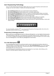
... menu. To access this utility, either click on the "Acer eNet Management" icon on your PC. T Acer eRecovery Management backs up to match your new Acer notebook. Right-click on the appropriate utility and select the Help or Tutorial function. T Acer ePower Management extends battery power via versatile usage profiles. You also have the option...
... menu. To access this utility, either click on the "Acer eNet Management" icon on your PC. T Acer eRecovery Management backs up to match your new Acer notebook. Right-click on the appropriate utility and select the Help or Tutorial function. T Acer ePower Management extends battery power via versatile usage profiles. You also have the option...

Aspire 7720 / 7720G Service Guide
Page 26
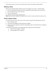
DC Mode (Battery mode) There are three pre-defined profiles - To create new power plan 1. Select one of the predefined power plan that is created. 20 Chapter 1 A new ... setting. 6. You can also define the power plan optimized for the newly created power plan. 3. AC Mode (Adapter mode) The default setting is "Maximum Performance." Acer ePower Management Acer ePower Management features a straightforward user interface. To launch it, select...
DC Mode (Battery mode) There are three pre-defined profiles - To create new power plan 1. Select one of the predefined power plan that is created. 20 Chapter 1 A new ... setting. 6. You can also define the power plan optimized for the newly created power plan. 3. AC Mode (Adapter mode) The default setting is "Maximum Performance." Acer ePower Management Acer ePower Management features a straightforward user interface. To launch it, select...

Aspire 7720 / 7720G Service Guide
Page 27
For additional power options, click "More Power option". Chapter 1 21 If auto-detection hardware is connected to an external device or project using the hot key: Fn + F5. Battery status For real-time battery life estimates based on current usage, refer to the time shown in the system, your computer's display to the system. Acer ePresentation Management Acer ePresentation Management lets you project your system display will be automatically switched out when an external display is implemented in the "Remaining Battery Life" field.
For additional power options, click "More Power option". Chapter 1 21 If auto-detection hardware is connected to an external device or project using the hot key: Fn + F5. Battery status For real-time battery life estimates based on current usage, refer to the time shown in the system, your computer's display to the system. Acer ePresentation Management Acer ePresentation Management lets you project your system display will be automatically switched out when an external display is implemented in the "Remaining Battery Life" field.

Aspire 7720 / 7720G Service Guide
Page 57
If the battery pack does not contain enough power to the bootable diskette. 3. Copy the flash utilities to finish BIOS flash, you may not boot the system because ...
If the battery pack does not contain enough power to the bootable diskette. 3. Copy the flash utilities to finish BIOS flash, you may not boot the system because ...

Aspire 7720 / 7720G Service Guide
Page 60
General Information Before You Begin Before proceeding with the disassembly procedure, make sure that you do the following: 1. Remove the battery pack. 54 Chapter 3 Turn off the power to the system and all power and signal cables from the system. 3. Unplug the AC adapter and all peripherals. 2.
General Information Before You Begin Before proceeding with the disassembly procedure, make sure that you do the following: 1. Remove the battery pack. 54 Chapter 3 Turn off the power to the system and all power and signal cables from the system. 3. Unplug the AC adapter and all peripherals. 2.

Aspire 7720 / 7720G Service Guide
Page 61
Start Battery Pack B*1 D*1 System Fan B*4 Thermal Module F*1 ODD Module CPU D*5 F*1 Thermal Door Memory Lower Case Assembly F*1 Mimi Cover F*2 HDD Door H*4 HDD Bracket HDD Middle Cover F*2 Keyboard C*2 LCD ...
Start Battery Pack B*1 D*1 System Fan B*4 Thermal Module F*1 ODD Module CPU D*5 F*1 Thermal Door Memory Lower Case Assembly F*1 Mimi Cover F*2 HDD Door H*4 HDD Bracket HDD Middle Cover F*2 Keyboard C*2 LCD ...

Aspire 7720 / 7720G Service Guide
Page 63
Slide the battery release latch then remove the battery. Chapter 3 57 Removing the Battery Pack 1. Unlock the battery lock (move the battery lock to the unlock position as shown). 2.
Slide the battery release latch then remove the battery. Chapter 3 57 Removing the Battery Pack 1. Unlock the battery lock (move the battery lock to the unlock position as shown). 2.

Aspire 7720 / 7720G Service Guide
Page 67
Disconnect the LCD cable and microphone cable from inside the battery compartment and the two screws fastening the LCD module. 3. Remove the four screws securing the hinges. Chapter 3 61 Turn the notebook over the keyboard as ...
Disconnect the LCD cable and microphone cable from inside the battery compartment and the two screws fastening the LCD module. 3. Remove the four screws securing the hinges. Chapter 3 61 Turn the notebook over the keyboard as ...
Aspire 7720 / 7720G Service Guide
Page 79
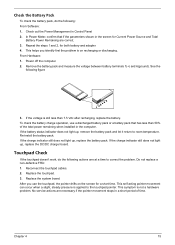
If any of the following list: T "Check the Power Adapter" on page 74 T "Check the Battery Pack" on page 75 Chapter 4 73 Press F2 in the message window. Follow the instructions in the ...is supplied. 3. Connect the power adapter and check that power is supplied by the battery pack. Go to main board). 2. Disconnect the power adapter and install the charged battery pack; Memory check Memory errors might stop system operations, show error messages on the...check in the test items. 3. then check that power is fully installed into the connector. Remove the battery pack. 2.
If any of the following list: T "Check the Power Adapter" on page 74 T "Check the Battery Pack" on page 75 Chapter 4 73 Press F2 in the message window. Follow the instructions in the ...is supplied. 3. Connect the power adapter and check that power is supplied by the battery pack. Go to main board). 2. Disconnect the power adapter and install the charged battery pack; Memory check Memory errors might stop system operations, show error messages on the...check in the test items. 3. then check that power is fully installed into the connector. Remove the battery pack. 2.

Aspire 7720 / 7720G Service Guide
Page 80
... of the power adapter for correct continuity and installation. 4. See the following : T Replace the System board. If the voltage is not corrected, see "Check the Battery Pack" on indicator does not light up, check the power cord of the power adapter cable.
... of the power adapter for correct continuity and installation. 4. See the following : T Replace the System board. If the voltage is not corrected, see "Check the Battery Pack" on indicator does not light up, check the power cord of the power adapter cable.
Aspire 7720 / 7720G Service Guide
Page 81
... the touchpad cables. 2. This symptom is still less than 50% of time. If the charge indicator still does not light up , replace the battery pack. Do not replace a non-defective FRU: 1. See the following figure 3. This self-acting pointer movement can occur when a slight, steady ...pressure is on the screen for a short time. No service actions are correct. 3. Power off the computer. 2. To check the battery charge operation, use the touchpad, the pointer drifts on recharging or discharging. Replace the system board. After you identify first the problem is ...
... the touchpad cables. 2. This symptom is still less than 50% of time. If the charge indicator still does not light up , replace the battery pack. Do not replace a non-defective FRU: 1. See the following figure 3. This self-acting pointer movement can occur when a slight, steady ...pressure is on the screen for a short time. No service actions are correct. 3. Power off the computer. 2. To check the battery charge operation, use the touchpad, the pointer drifts on recharging or discharging. Replace the system board. After you identify first the problem is ...
Aspire 7720 / 7720G Service Guide
Page 83
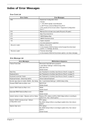
... In this situation BIOS will issue 4 short beeps then shut down system, not show . Keyboard locked - Default configuration used RTC battery Run BIOS Setup Utility to reconfigure system time, then reboot system. Incorrect password is dead - Unlock key switch Unlock external keyboard Monitor... 071 072 110 Error Messages Equipment Configuration Error Causes: 1. IDE Primary Channel Master Drive Error (THe causes will show message. Battery critical LOW In this situation BIOS will shut down system, no message will be shown before "Equipment Configuration Error") Memory Error ...
... In this situation BIOS will issue 4 short beeps then shut down system, not show . Keyboard locked - Default configuration used RTC battery Run BIOS Setup Utility to reconfigure system time, then reboot system. Incorrect password is dead - Unlock key switch Unlock external keyboard Monitor... 071 072 110 Error Messages Equipment Configuration Error Causes: 1. IDE Primary Channel Master Drive Error (THe causes will show message. Battery critical LOW In this situation BIOS will shut down system, no message will be shown before "Equipment Configuration Error") Memory Error ...

Aspire 7720 / 7720G Service Guide
Page 84
...System board DIMM System board DIMM System board DIMM System board Run "Load Default Settings" in Sequence RTC battery Run BIOS Setup Utility to reconfigure system time, then reboot system. RTC battery System board Enter Setup and see if fixed disk and drive A: are properly identified. Default configuration used... Memory size found FRU/Action in BIOS Setup Utility. System board Run "Load Default Settings" in BIOS Setup Utility. RTC battery System board DIMM BIOS ROM System board None BIOS ROM System board Run "Load Default Settings" in BIOS Setup Utility. RTC...
...System board DIMM System board DIMM System board DIMM System board Run "Load Default Settings" in Sequence RTC battery Run BIOS Setup Utility to reconfigure system time, then reboot system. RTC battery System board Enter Setup and see if fixed disk and drive A: are properly identified. Default configuration used... Memory size found FRU/Action in BIOS Setup Utility. System board Run "Load Default Settings" in BIOS Setup Utility. RTC battery System board DIMM BIOS ROM System board None BIOS ROM System board Run "Load Default Settings" in BIOS Setup Utility. RTC...

Aspire 7720 / 7720G Service Guide
Page 85
... and power adapter). LED board. Reconnect the LCD connectors. No beep, power-on indicator turns on LCD during POST but system runs correctly. Power source (battery pack and power adapter). See "Power System Check" on an external CRT. But you can see POST on page 73.. See "Power System Check" on...
... and power adapter). LED board. Reconnect the LCD connectors. No beep, power-on indicator turns on LCD during POST but system runs correctly. Power source (battery pack and power adapter). See "Power System Check" on an external CRT. But you can see POST on page 73.. See "Power System Check" on...
Aspire 7720 / 7720G Service Guide
Page 90
... and power adapter). Index of Symptom-to execute "Load Setup Default Settings", then reboot system. Battery pack Power adapter Hard drive & battery connection board System board Power source (battery pack and power adapter). Reconnect the LCD connectors. The system doesn't power-off or on, but ...'t power-on page 73. See "Power System Check" on page 73. System board 84 Chapter 4 Battery pack Power adapter Hard drive & battery connection board System board Power source (battery pack and power adapter). See "Power System Check" on page 73. Hold and press the power switch...
... and power adapter). Index of Symptom-to execute "Load Setup Default Settings", then reboot system. Battery pack Power adapter Hard drive & battery connection board System board Power source (battery pack and power adapter). Reconnect the LCD connectors. The system doesn't power-off or on, but ...'t power-on page 73. See "Power System Check" on page 73. System board 84 Chapter 4 Battery pack Power adapter Hard drive & battery connection board System board Power source (battery pack and power adapter). See "Power System Check" on page 73. Hold and press the power switch...

Aspire 7720 / 7720G Service Guide
Page 91
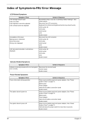
...board See "Save to Disk (S4)" on page 75. Action in Sequence See "Check the Battery Pack" on page 45. The system doesn't enter standby mode after opening the LCD. Battery pack System board PCMCIA-Related Symptoms Symptom / Error System cannot detect the PC Card (PCMCIA) PCMCIA...closing the LCD The system doesn't resume from actual size. LCD cover switch System board Chapter 4 85 Power-Related Symptoms Symptom / Error Battery can't be charged Action in Sequence Enter BIOS Setup Utility to execute "Load Default Settings, then reboot system. Action in Sequence PCMCIA slot...
...board See "Save to Disk (S4)" on page 75. Action in Sequence See "Check the Battery Pack" on page 45. The system doesn't enter standby mode after opening the LCD. Battery pack System board PCMCIA-Related Symptoms Symptom / Error System cannot detect the PC Card (PCMCIA) PCMCIA...closing the LCD The system doesn't resume from actual size. LCD cover switch System board Chapter 4 85 Power-Related Symptoms Symptom / Error Battery can't be charged Action in Sequence Enter BIOS Setup Utility to execute "Load Default Settings, then reboot system. Action in Sequence PCMCIA slot...


