Aspire 7560, 7560G Service Guide
Page 3
...constant width bold. Example: At the prompt, type run -m Keyboard keys are shown in angle brackets (< >). Example: After entering data, press Enter. Batteries and Circuit Boards >10 cm² have been highlighted with a yellow rectangle. IMPORTANT: Indicates information that represents information displayed on a computer screen, such as command...to input, and error messages) are used in this manual: ! CAUTION: Indicates a potential loss of an option, or completing a task. WARNING: Indicates a potential for battery and circuit board disposal. iii
...constant width bold. Example: At the prompt, type run -m Keyboard keys are shown in angle brackets (< >). Example: After entering data, press Enter. Batteries and Circuit Boards >10 cm² have been highlighted with a yellow rectangle. IMPORTANT: Indicates information that represents information displayed on a computer screen, such as command...to input, and error messages) are used in this manual: ! CAUTION: Indicates a potential loss of an option, or completing a task. WARNING: Indicates a potential for battery and circuit board disposal. iii
Aspire 7560, 7560G Service Guide
Page 5
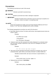
... Specifications Features 1-5 Operating System 1-5 Platform 1-5 System Memory 1-5 Display 1-5 Graphics 1-6 Audio Subsystem 1-7 Storage Subsystem 1-7 Optical Media Drive 1-7 Communication 1-7 Privacy Control 1-8 Dimensions and Weight 1-8 Power Adapter and Battery 1-8 Special Keys and Controls 1-8 I/O Ports 1-9 Environment 1-9 Optional Items 1-9 Warranty 1-9 Software 1-10 Notebook Tour 1-11 Top View 1-11 Closed Front View 1-13 Rear View 1-14 Left...
... Specifications Features 1-5 Operating System 1-5 Platform 1-5 System Memory 1-5 Display 1-5 Graphics 1-6 Audio Subsystem 1-7 Storage Subsystem 1-7 Optical Media Drive 1-7 Communication 1-7 Privacy Control 1-8 Dimensions and Weight 1-8 Power Adapter and Battery 1-8 Special Keys and Controls 1-8 I/O Ports 1-9 Environment 1-9 Optional Items 1-9 Warranty 1-9 Software 1-10 Notebook Tour 1-11 Top View 1-11 Closed Front View 1-13 Rear View 1-14 Left...
Aspire 7560, 7560G Service Guide
Page 6
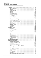
... 1-37 Bluetooth Interface 1-38 Bluetooth Module 1-38 Camera 1-38 Mini Card 1-38 Audio Codec and Amplifier 1-39 Audio Interface 1-39 Wireless Module 802.11b/g/n 1-40 Battery 1-40 VRAM 1-40 USB Port 1-40 HDMI Port 1-41 AC Adapter 1-41 System Power Management 1-41 Card Reader 1-42 System LED Indicator 1-42 System DMA...
... 1-37 Bluetooth Interface 1-38 Bluetooth Module 1-38 Camera 1-38 Mini Card 1-38 Audio Codec and Amplifier 1-39 Audio Interface 1-39 Wireless Module 802.11b/g/n 1-40 Battery 1-40 VRAM 1-40 USB Port 1-40 HDMI Port 1-41 AC Adapter 1-41 System Power Management 1-41 Card Reader 1-42 System LED Indicator 1-42 System DMA...
Aspire 7560, 7560G Service Guide
Page 7
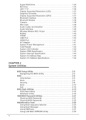
... Information 3-5 Recommended Equipment 3-5 Maintenance Flowchart 3-6 Getting Started 3-7 Dummy Card Removal 3-8 Dummy Card Installation 3-8 Battery Removal 3-9 Battery Installation 3-9 ODD Module Removal 3-11 ODD Module Installation 3-13 Logic Door Removal 3-14 Logic Door Installation 3-14...USB Module Removal 3-38 USB Module Installation 3-39 Bluetooth Module Removal 3-40 Bluetooth Module Installation 3-41 RTC Battery Removal 3-42 RTC Battery Installation 3-42 Speaker Module Removal 3-43 Speaker Module Installation 3-44 Mainboard Removal 3-45 Mainboard Installation 3-47...
... Information 3-5 Recommended Equipment 3-5 Maintenance Flowchart 3-6 Getting Started 3-7 Dummy Card Removal 3-8 Dummy Card Installation 3-8 Battery Removal 3-9 Battery Installation 3-9 ODD Module Removal 3-11 ODD Module Installation 3-13 Logic Door Removal 3-14 Logic Door Installation 3-14...USB Module Removal 3-38 USB Module Installation 3-39 Bluetooth Module Removal 3-40 Bluetooth Module Installation 3-41 RTC Battery Removal 3-42 RTC Battery Installation 3-42 Speaker Module Removal 3-43 Speaker Module Installation 3-44 Mainboard Removal 3-45 Mainboard Installation 3-47...
Aspire 7560, 7560G Service Guide
Page 12
Features 1-5 Operating System 1-5 Platform 1-5 System Memory 1-5 Display 1-5 Graphics 1-6 Audio Subsystem 1-7 Storage Subsystem 1-7 Optical Media Drive 1-7 Communication 1-7 Privacy Control 1-8 Dimensions and Weight 1-8 Power Adapter and Battery 1-8 Special Keys and Controls 1-8 I/O Ports 1-9 Environment 1-9 Optional Items 1-9 Warranty 1-9 Software 1-10 Notebook Tour 1-11 Top View 1-11 Closed Front View 1-13 Rear View 1-14 Left ...
Features 1-5 Operating System 1-5 Platform 1-5 System Memory 1-5 Display 1-5 Graphics 1-6 Audio Subsystem 1-7 Storage Subsystem 1-7 Optical Media Drive 1-7 Communication 1-7 Privacy Control 1-8 Dimensions and Weight 1-8 Power Adapter and Battery 1-8 Special Keys and Controls 1-8 I/O Ports 1-9 Environment 1-9 Optional Items 1-9 Warranty 1-9 Software 1-10 Notebook Tour 1-11 Top View 1-11 Closed Front View 1-13 Rear View 1-14 Left ...
Aspire 7560, 7560G Service Guide
Page 18
...;ACPI 3.0 CPU power management standard: supports Standby and Hibernation power-saving modes Battery 48 Wh 4400 mAh 6-cell Li-ion standard battery pack Battery life: TBC hours ENERGY STAR® Power adapter Aspire 7560 0 3-pin 65 W AC adapter: 95 (W) ...Aspire 7560G 0 3-pin 90 W AC adapter: 133 (W) x 59 (D) x 31 (H) mm (5.23 x 2.32 x 1.22 inches) 390 g (0.86 lbs.) with 180 cm DC cable Special Keys and Controls 0 Keyboard 103-/104-/107-key Acer ...
...;ACPI 3.0 CPU power management standard: supports Standby and Hibernation power-saving modes Battery 48 Wh 4400 mAh 6-cell Li-ion standard battery pack Battery life: TBC hours ENERGY STAR® Power adapter Aspire 7560 0 3-pin 65 W AC adapter: 95 (W) ...Aspire 7560G 0 3-pin 90 W AC adapter: 133 (W) x 59 (D) x 31 (H) mm (5.23 x 2.32 x 1.22 inches) 390 g (0.86 lbs.) with 180 cm DC cable Special Keys and Controls 0 Keyboard 103-/104-/107-key Acer ...
Aspire 7560, 7560G Service Guide
Page 19
...support External display (VGA) port Headphone/speaker jack, supporting 3.5 mm headset with built-in microphone for Acer smart handhelds Microphone-in jack Ethernet (RJ-45) port DC-in jack for AC adapter ...80% Optional Items 0 1/2/4 GB DDR3 soDIMM module 6-cell Li-ion battery pack External USB 56K modem Aspire 7560 0 3-pin 65 W AC adapter Aspire 7560G 0 3-pin 90W AC adapter Warranty 0 One-year International Travelers...
...support External display (VGA) port Headphone/speaker jack, supporting 3.5 mm headset with built-in microphone for Acer smart handhelds Microphone-in jack Ethernet (RJ-45) port DC-in jack for AC adapter ...80% Optional Items 0 1/2/4 GB DDR3 soDIMM module 6-cell Li-ion battery pack External USB 56K modem Aspire 7560 0 3-pin 65 W AC adapter Aspire 7560G 0 3-pin 90W AC adapter Warranty 0 One-year International Travelers...
Aspire 7560, 7560G Service Guide
Page 23
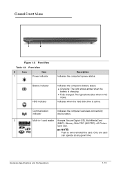
.... Charging: The light shows amber when the battery is active. Hardware Specifications and Configurations 1-13 Indicates when the hard disk drive is charging. Fully charged: The light shows blue when in -1 card ...
.... Charging: The light shows amber when the battery is active. Hardware Specifications and Configurations 1-13 Indicates when the hard disk drive is charging. Fully charged: The light shows blue when in -1 card ...
Aspire 7560, 7560G Service Guide
Page 24
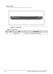
Rear View 0 1 Figure 1-3. Rear View # Icon Item 1 Battery bay Description Houses the computer's battery pack. 1-14 Hardware Specifications and Configurations Rear View Table 1-3.
Rear View 0 1 Figure 1-3. Rear View # Icon Item 1 Battery bay Description Houses the computer's battery pack. 1-14 Hardware Specifications and Configurations Rear View Table 1-3.
Aspire 7560, 7560G Service Guide
Page 28
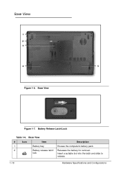
Base View 0 5 Figure 1-7. Releases the battery for removal. Base View # Icon Item 1 Battery bay 2 Battery release latch/ lock Description Houses the computer's battery pack. Insert a suitable tool into the latch and slide to release. 1-18 Hardware Specifications and Configurations Battery Release Latch/Lock Table 1-6. Base View 1 2 3 4 Figure 1-6.
Base View 0 5 Figure 1-7. Releases the battery for removal. Base View # Icon Item 1 Battery bay 2 Battery release latch/ lock Description Houses the computer's battery pack. Insert a suitable tool into the latch and slide to release. 1-18 Hardware Specifications and Configurations Battery Release Latch/Lock Table 1-6. Base View 1 2 3 4 Figure 1-6.
Aspire 7560, 7560G Service Guide
Page 36
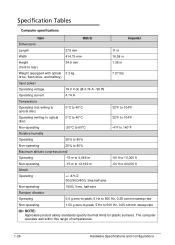
... in Width 414.75 mm 16.59 in Height (front to rear) 34.6 mm 1.38 in Weight (equipped with optical 3.3 kg drive, flash drive, and battery) 7.27 lbs Input power Operating voltage 19.0 V dc @ 4.74 A - 90 W Operating current 4.74 A Temperature Operating (not writing to optical disc) 0°C to 40°C 32...
... in Width 414.75 mm 16.59 in Height (front to rear) 34.6 mm 1.38 in Weight (equipped with optical 3.3 kg drive, flash drive, and battery) 7.27 lbs Input power Operating voltage 19.0 V dc @ 4.74 A - 90 W Operating current 4.74 A Temperature Operating (not writing to optical disc) 0°C to 40°C 32...
Aspire 7560, 7560G Service Guide
Page 50
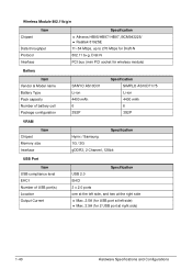
... 11~54 Mbps, up to 270 Mbps for Draft-N 802.11 b+g, Drat-N PCI bus (mini PCI socket for wireless module) Battery Item Vendor & Model name Battery Type Pack capacity Number of battery cell Package configuration SANYO AS10D31 Li-ion 4400 mAh 6 3S2P Specification SIMPLO AS10D71/75 Li-ion 4400 mAh 6 3S2P VRAM Item...
... 11~54 Mbps, up to 270 Mbps for Draft-N 802.11 b+g, Drat-N PCI bus (mini PCI socket for wireless module) Battery Item Vendor & Model name Battery Type Pack capacity Number of battery cell Package configuration SANYO AS10D31 Li-ion 4400 mAh 6 3S2P Specification SIMPLO AS10D71/75 Li-ion 4400 mAh 6 3S2P VRAM Item...
Aspire 7560, 7560G Service Guide
Page 52
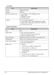
...Amber color off Charging Amber solid on - Discharging state 1-42 Hardware Specifications and Configurations Battery charging with AC Blue color solid on - Battery abnormal stop charge or batter in low power state Discharging Amber and blinking - Card ...Reader Item Chipset Package Maximum supported size Features System LED Indicator Item Lock System state HDD access state Wireless state Power button backlight Battery state Specification Realtek RTS-5138 QFN 24P SD: 2GB/SDHC: 4GB~32GB/SHXC: 2TB MMC: 32GB ...
...Amber color off Charging Amber solid on - Discharging state 1-42 Hardware Specifications and Configurations Battery charging with AC Blue color solid on - Battery abnormal stop charge or batter in low power state Discharging Amber and blinking - Card ...Reader Item Chipset Package Maximum supported size Features System LED Indicator Item Lock System state HDD access state Wireless state Power button backlight Battery state Specification Realtek RTS-5138 QFN 24P SD: 2GB/SDHC: 4GB~32GB/SHXC: 2TB MMC: 32GB ...
Aspire 7560, 7560G Service Guide
Page 73
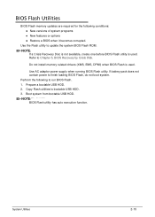
... memory updates are required for the following to update the system BIOS Flash ROM. Use AC adaptor power supply when running BIOS Flash utility. If battery pack does not contain power to bootable USB HDD. 3. Prepare a bootable USB HDD. 2. Boot system from bootable USB HDD. NOTE: NOTE: BIOS Flash utility has...
... memory updates are required for the following to update the system BIOS Flash ROM. Use AC adaptor power supply when running BIOS Flash utility. If battery pack does not contain power to bootable USB HDD. 3. Prepare a bootable USB HDD. 2. Boot system from bootable USB HDD. NOTE: NOTE: BIOS Flash utility has...
Aspire 7560, 7560G Service Guide
Page 76
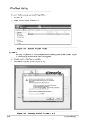
Double click the WinFlash executable. 4. Click OK to OS. 2. Boot to begin the update. (Figure 2-19) 2-18 Figure 2-19. Winflash Program Folder NOTE: NOTE: Flashing of 2) System Utilities Executing Winflash Program (1 of system BIOS cannot be performed on battery power. Make sure AC adapter is connecting to use the WinFlash Utility: 1. WinFlash Utility 0 Perform the following to device before executing program. 3. Open Winflash folder. (Figure 2-18) Figure 2-18.
Double click the WinFlash executable. 4. Click OK to OS. 2. Boot to begin the update. (Figure 2-19) 2-18 Figure 2-19. Winflash Program Folder NOTE: NOTE: Flashing of 2) System Utilities Executing Winflash Program (1 of system BIOS cannot be performed on battery power. Make sure AC adapter is connecting to use the WinFlash Utility: 1. WinFlash Utility 0 Perform the following to device before executing program. 3. Open Winflash folder. (Figure 2-18) Figure 2-18.
Aspire 7560, 7560G Service Guide
Page 90
... 3-5 Recommended Equipment 3-5 Maintenance Flowchart 3-6 Getting Started 3-7 Dummy Card Removal 3-8 Dummy Card Installation 3-8 Battery Removal 3-9 Battery Installation 3-9 ODD Module Removal 3-11 ODD Module Installation 3-13 Logic Door Removal 3-14 Logic Door Installation...37 USB Module Removal 3-38 USB Module Installation 3-39 Bluetooth Module Removal 3-40 Bluetooth Module Installation 3-41 RTC Battery Removal 3-42 RTC Battery Installation 3-42 Speaker Module Removal 3-43 Speaker Module Installation 3-44 Mainboard Removal 3-45 Mainboard Installation 3-47 Thermal ...
... 3-5 Recommended Equipment 3-5 Maintenance Flowchart 3-6 Getting Started 3-7 Dummy Card Removal 3-8 Dummy Card Installation 3-8 Battery Removal 3-9 Battery Installation 3-9 ODD Module Removal 3-11 ODD Module Installation 3-13 Logic Door Removal 3-14 Logic Door Installation...37 USB Module Removal 3-38 USB Module Installation 3-39 Bluetooth Module Removal 3-40 Bluetooth Module Installation 3-41 RTC Battery Removal 3-42 RTC Battery Installation 3-42 Speaker Module Removal 3-43 Speaker Module Installation 3-44 Mainboard Removal 3-45 Mainboard Installation 3-47 Thermal ...
Aspire 7560, 7560G Service Guide
Page 97
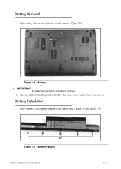
Slide battery lock switch (A) to slots (E) in battery bay. (Figure 3-5 and Figure 3-6) D Figure 3-5. Battery Installation 0 1. Align flanges (D) on battery to the unlock position. (Figure 3-4) C A B Figure 3-4. Use slot (B) to pull battery (C) from battery bay and remove battery from lower cover. IMPORTANT: Follow local regulations for battery disposal. 2. Battery Flanges Machine Maintenance Procedures 3-9 Battery ? Battery Removal 0 1.
Slide battery lock switch (A) to slots (E) in battery bay. (Figure 3-5 and Figure 3-6) D Figure 3-5. Battery Installation 0 1. Align flanges (D) on battery to the unlock position. (Figure 3-4) C A B Figure 3-4. Use slot (B) to pull battery (C) from battery bay and remove battery from lower cover. IMPORTANT: Follow local regulations for battery disposal. 2. Battery Flanges Machine Maintenance Procedures 3-9 Battery ? Battery Removal 0 1.
Aspire 7560, 7560G Service Guide
Page 98
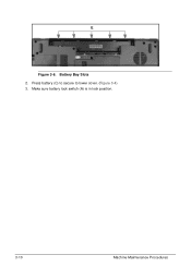
E Figure 3-6. Press battery (C) to secure to lower cover. (Figure 3-4) 3. Make sure battery lock switch (A) is in lock position. 3-10 Machine Maintenance Procedures Battery Bay Slots 2.
E Figure 3-6. Press battery (C) to secure to lower cover. (Figure 3-4) 3. Make sure battery lock switch (A) is in lock position. 3-10 Machine Maintenance Procedures Battery Bay Slots 2.
Aspire 7560, 7560G Service Guide
Page 99
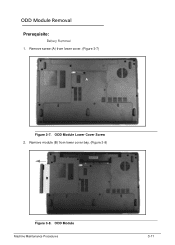
ODD Module Machine Maintenance Procedures 3-11 Remove screw (A) from lower cover bay. (Figure 3-8) B Figure 3-8. Remove module (B) from lower cover. (Figure 3-7) A Figure 3-7. ODD Module Removal 0 Prerequisite: Battery Removal 1. ODD Module Lower Cover Screw 2.
ODD Module Machine Maintenance Procedures 3-11 Remove screw (A) from lower cover bay. (Figure 3-8) B Figure 3-8. Remove module (B) from lower cover. (Figure 3-7) A Figure 3-7. ODD Module Removal 0 Prerequisite: Battery Removal 1. ODD Module Lower Cover Screw 2.
Aspire 7560, 7560G Service Guide
Page 101
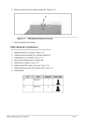
... 3-9) 6. Remove screws (D) from module. Install bracket (E) on module. (Figure 3-10) 4. Install and secure screw (A) to module bracket (E). 3. Install module (B) in lower cover bay. (Figure 3-8) 7. Install battery. Secure bezel locking latch to module tray. 5. ODD Module Bracket and Screws 7. Remove bracket from module bracket (E). (Figure 3-11) E D Figure 3-11. Install bezel (C) on module...
... 3-9) 6. Remove screws (D) from module. Install bracket (E) on module. (Figure 3-10) 4. Install and secure screw (A) to module bracket (E). 3. Install module (B) in lower cover bay. (Figure 3-8) 7. Install battery. Secure bezel locking latch to module tray. 5. ODD Module Bracket and Screws 7. Remove bracket from module bracket (E). (Figure 3-11) E D Figure 3-11. Install bezel (C) on module...


