Battery For Aspire 5732Z - Acer
Battery For Aspire 5732Z
Related Manual Pages

Similar Questions

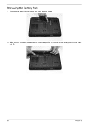
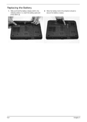
Instructions To Replace Battery On Acer Aspire 5732z
Need instructions on how to replace battery.
Need instructions on how to replace battery.
(Posted by mackie134 10 years ago)

So...how Do I Even Get To My Battery On The Aspire V5-122p-0864?
just that! got this as part of the class action suit, but it only worked a couple weeks before batte...
just that! got this as part of the class action suit, but it only worked a couple weeks before batte...
(Posted by nancyhill53 10 years ago)


Bios Battery
I tried hard to find the bios battery of my acer travelmate 4330 laptop bt I cant find it can u plz ...
I tried hard to find the bios battery of my acer travelmate 4330 laptop bt I cant find it can u plz ...
(Posted by zainzoni14 12 years ago)

Battery Doesn't Charge
What software in my computer allows my battery to charge? This is because I have been unable to char...
What software in my computer allows my battery to charge? This is because I have been unable to char...
(Posted by gaiusnti 13 years ago)